

Watchguard DVR8ENT3 Product Manual
MODEL: DVR8ENT3
8 Channel H.264 DVR
With Push Video Notification
‘Product Manual’
N517
www.watchguardalarms.com.au

409Z
a798_796_792_m686_688_752_757_759_k675_677_677l_679_pv_h_Manual_V1.3
H.264 Network DVR
User Manual
GUI Display with USB Mouse Control
Please read instructions thoroughly before operation and retain it for future reference.
For the actual display & operation, please refer to your DVR in hand.
IMPORTANT SAFEGUARD
CAUTION
RISK OF ELECTRIC SHOCK
CAUTION:
To reduce the risk of electric shock, do not expose this apparatus to rain or moisture. Only operate this
apparatus from the type of power source indicated on the label. The company shall not be liable for any
damages arising out of any improper use, even if we have been advised of the possibility of such
damages.
The lightning flash with arrowhead symbol, within an equilateral triangle, is intended to alert the
user to the presence of uninsulated “dangerous voltage” within the product’s enclosure that may
be of sufficient magnitude to constitute a risk of electric shock to persons.
This exclamation point within an equilateral triangle is intended to alert the user to the presence
of important operating and maintenance (servicing) instructions in the literature accompanying
the appliance.
All lead-free products offered by the company comply with the requirements of the European law
on the Restriction of Hazardous Substances (RoHS) directive, which means our manufacture
processes and products are strictly “lead-free” and without the hazardous substances cited in the
directive.
The crossed-out wheeled bin mark symbolizes that within the European Union the product must
be collected separately at the product end-of-life. This applies to your product and any
peripherals marked with this symbol. Do not dispose of these products as unsorted municipal
waste. Contact your local dealer for procedures for recycling this equipment.
This apparatus is manufactured to comply with the radio interference requirements.
Federal Communications Commission Interference Statement
This equipment has been tested and found to comply with the limits for a Class A digital device, pursuant to Part
15 of the FCC Rules. These limits are designed to provide reasonable protection against harmful interference
when the equipment is operated in a commercial environment. This equipment generates, uses, and can radiate
radio frequency energy and, if not installed and used in accordance with the instruction manual, may cause
harmful interference to radio communications. Operation of this equipment in a residential area is likely to cause
harmful interference in which case the user will be required to correct the interference at his own expense.
Trademark Acknowledgements
iPhone® is the registered trademark of Apple Inc.
BlackBerry® and related trademarks, names and logos are the property of Research In Motion Limited and are
registered and/or used in the U.S. and countries around the world. Used under license from Research In Motion
Limited.
Microsoft®, Windows®, Internet Explorer®, Mozilla® Firefox®, Google Chrome™, QuickTime®, Windows®
Mobile & Symbian® mentioned in this document are the registered trademarks of their respective holders.
Disclaimer
The information in this manual was current when released. We reserve the right to revise or remove any content in
this manual at any time. We do not warrant or assume any legal liability or responsibility for the accuracy,
completeness, or usefulness of this manual. For the actual display & operation, please refer to your DVR in hand.
The content of this manual is subject to change without notice.

Grounding
This is a Safety Class 1 Product (provided with a protective earthing ground incorporated in the power cord). The
mains plug shall only be inserted in a socket outlet provided with a protective earth contact. Any interruption of the
protective conductor inside or outside of the instrument is likely to make the instrument dangerous. Intentional
interruption is prohibited.
Water & Moisture
Do not expose this product to dripping or splashing and that no objects filled with liquids, such as vases, shall be
placed on the product.
MPEG4 Licensing
THIS PRODUCT IS LICENSED UNDER THE MPEG-4 VISUAL PATENT PORTFOLIO LICENSE FOR THE
PERSONAL AND NON-COMMERCIAL USE OF A CONSUMER FOR (i) ENCODING VIDEO IN COMPLIANCE
WITH THE MPEG-4 VISUAL STANDARD (“MPEG-4 VIDEO”) AND/OR (ii) DECODING MPEG-4 VIDEO THAT
WAS ENCODED BY A CONSUMER ENGAGED IN A PERSONAL AND NON-COMMERCIAL ACTIVITY AND/OR
WAS OBTAINED FROM A VIDEO PROVIDER LICENSED BY MPEG LA TO PROVIDE MPEG-4 VIDEO. NO
LICENSE IS GRANTED OR SHALL BE IMPLIED FOR ANY OTHER USE. ADDITIONAL INFORMATION
INCLUDING THAT RELATING TO PROMOTIONAL INTERNAL AND COMMERCIAL USES AND LICENSING
MAY BE OBTAINED FROM MPEG LA, LLC. SEE HTTP://WWW.MPEGLA.COM.
GPL Licensing
This product contains codes which are developed by Third-Party-Companies and which
are subject to the GNU General Public License (“GPL”) or the GNU Lesser Public License
(“LGPL”).
The GPL Code used in this product is released without warranty and is subject to the
copyright of the corresponding author.
Further source codes which are subject to the GPL-licenses are available upon request.
We are pleased to provide our modifications to the Linux Kernel, as well as a few new
commands, and some tools to get you into the code. The codes are provided on the FTP
site, and please download them from the following site or you can refer to your distributor:
http://download.dvrtw.com.tw/GPL/DVR/H-Seriers/linux.tar.gz

TABLE OF CONTENTS
1. BEFORE USING THIS DVR .................................................................................. 1
1.1 Package Content ....................................................................................................................... 1
1.2 Front Panel ................................................................................................................................ 1
1.3 Rear Panel................................................................................................................................. 2
2. CONNECTION AND SETUP.................................................................................. 4
2.1 SATA HDD Installation ............................................................................................................... 4
2.2 Camera Connection................................................................................................................... 6
2.2.1 Normal Camera Connection..............................................................................................................6
2.2.2 PTZ Camera Connection...................................................................................................................7
2.3 External Device Connection....................................................................................................... 8
2.4 DVR Power On .......................................................................................................................... 9
2.5 Date and Time Setting ............................................................................................................... 9
2.6 Clear Hard Disk........................................................................................................................ 10
2.7 Password Setting..................................................................................................................... 10
3. GUI DISPLAY WITH USB MOUSE CONTROL................................................... 12
3.1 Connect USB Mouse ............................................................................................................... 12
3.2 Quick Menu Bar ....................................................................................................................... 12
3.2.1 Channel Switch............................................................................................................................... 13
3.2.2 PTZ Control Panel.......................................................................................................................... 13
3.3 Main Menu ............................................................................................................................... 14
4. BASIC OPERATION ............................................................................................ 15
4.1 Live Page................................................................................................................................. 15
4.2 Record Icon .............................................................................................................................15
4.3 Playback .................................................................................................................................. 16
4.3.1 Playback Control ............................................................................................................................ 16
4.3.2 Event Search.................................................................................................................................. 17
4.3.3 Audio Playback ............................................................................................................................... 17
4.4 User Level Switch .................................................................................................................... 17
4.5 System Sources Reallocation (For 4CH Models Only) ............................................................ 18
5. FREQUENTLY-USED FUNCTIONS .................................................................... 19
5.1 Push Video Configuration ........................................................................................................ 19
5.1.1 PIN Connection .............................................................................................................................. 19
A2.2 Configuration................................................................................................................................... 20
5.2 Quick Search ........................................................................................................................... 22
5.3 Record ..................................................................................................................................... 23
5.3.1 Quick record setting........................................................................................................................ 23
5.3.2 Detailed record setting.................................................................................................................... 24
5.4 Schedule Setting...................................................................................................................... 25
5.4.1 Record Timer.................................................................................................................................. 25
5.4.2 Detection Timer .............................................................................................................................. 26

5.4.3 Alarm Timer .................................................................................................................................... 26
5.5 Detection Setting ..................................................................................................................... 27
5.6 PTZ Camera Setting ................................................................................................................ 28
5.7 System Setting......................................................................................................................... 29
5.7.1 Password Setting............................................................................................................................ 29
5.7.2 System Upgrade............................................................................................................................. 29
5.7.3 Backup & Restore Configurations .................................................................................................. 30
5.7.4 Video Backup ................................................................................................................................. 30
5.7.5 Event Log Backup .......................................................................................................................... 32
5.7.6 Clear All HDD Data......................................................................................................................... 33
5.8 Network.................................................................................................................................... 33
5.8.1 STATIC ........................................................................................................................................... 33
5.8.2 PPPOE ........................................................................................................................................... 34
5.8.3 DHCP ............................................................................................................................................. 35
5.8.4 DDNS ............................................................................................................................................. 35
5.9 Event Notifications ................................................................................................................... 36
5.9.1 FTP................................................................................................................................................. 36
5.9.2 E-MAIL............................................................................................................................................ 37
5.10 VGA Output Resolution Support............................................................................................ 38
5.11 System Sources Reallocation (For 4CH Models Only) .......................................................... 39
6. REMOTE OPERATION........................................................................................ 40
6.1 Supplied Licensed Software .................................................................................................... 40
6.1.1 Installation & Network Connection ................................................................................................. 40
6.1.2 Control Panel Overview.................................................................................................................. 42
6.1.3. General Operation......................................................................................................................... 44
6.1.4. E-Map ............................................................................................................................................ 48
6.2 Web Browser ........................................................................................................................... 53
6.2.1 Event Download & Playback .......................................................................................................... 55
APPENDIX 1 SPECIFICATIONS ............................................................................. 57
APPENDIX 2 COMPATIBLE USB FLASH DRIVE LIST ......................................... 67
APPENDIX 3 COMPATIBLE SATA HDD LIST........................................................ 68
APPENDIX 4 MAIN MENU STRUCTURE ............................................................... 69
APPENDIX 5 DVR BATTERY REPLACEMENT...................................................... 71
APPENDIX 6 PIN CONFIGURATION...................................................................... 72
A6. Models without HD video output..............................................................................................72
A2. Models with HD video output................................................................................................... 76
APPENDIX 7 MOBILE SURVEILLANCE VIA EAGLEEYES .................................. 79
A7.1 Prerequisites ......................................................................................................................... 79
A7.2 Where to download ............................................................................................................... 79
APPENDIX 8 DVD- / CD-ROM COMPATIBLE LIST ............................................... 80
APPENDIX 9 DVD WRITER INSTALLATION ......................................................... 82
BEFORE USING THIS DVR
1
1. BEFORE USING THIS DVR
1.1 Package Content
Standard Package
DVR HDD screws
IR remote controller Manual for IR remote controller
Adapter & power cord
Optional Accessories
IR Receiver extension cable CD manual
USB Mouse I/O board
1.2 Front Panel
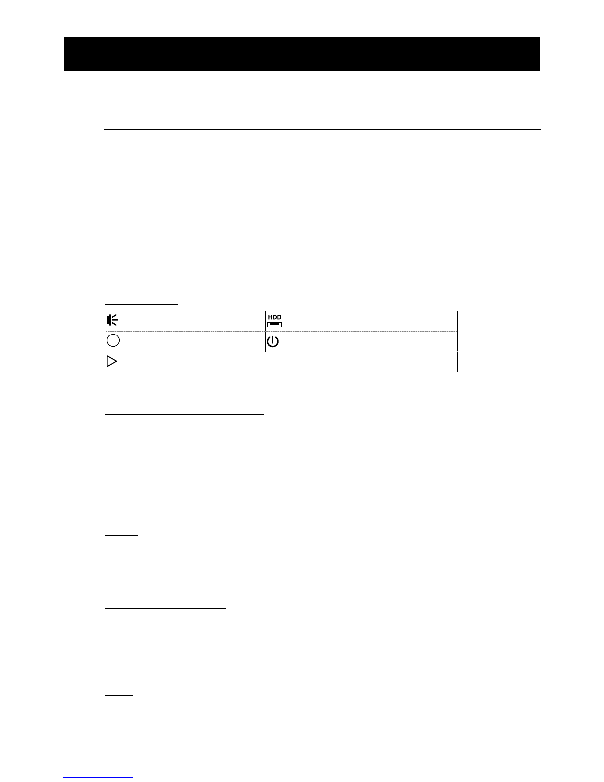
1) LED Indicators
*
An alarm is triggered.
HDD is reading or recording.
*
Timer recording is on.
DVR is powered on.
*
Under playback status.
* For selected models only
2) (▲) / (▼) / (◄) / (►)
Press ▲ / ▼ / ◄ / ► to move up / down / left / right.
In the playback mode:
Press “” to pause playback.
Press “” to stop playback.
Press ““ to fast forward.
Press ““ to fast rewind.
3) MENU
Press “MENU” to enter the main menu.
4) ENTER
Press “ENTER” to confirm the setting.
5) LIST (Event List Search)
Press to quickly search the recorded files by event lists: RECORD / MOTION / ALARM /
TIME, or select FULL to show all the event logs.
To quickly search the time you want, select “QUICK SEARCH”. Set the time range you
want, and select “SUBMIT” to play the recorded video clip during the specified time.
6) PLAY
Press to playback the latest recorded data.
BEFORE USING THIS DVR
2
7) SLOW
In the playback mode, press to show slow playback.
8) ZOOM
Press to enlarge the picture of selected channel in the FRAME or FIELD recording
mode.
9) SEQ
Press to display each channel in full screen one by one starting from CH1. When the last
channel is displayed, it will repeat from CH1 again. To exit this mode, press “SEQ”
again.
10)
Press to show the 4-channel display mode.
11) CH1 ~ 16 / 1 ~ 8 / 1 ~ 4
Press the channel number keys to select the channel to display.
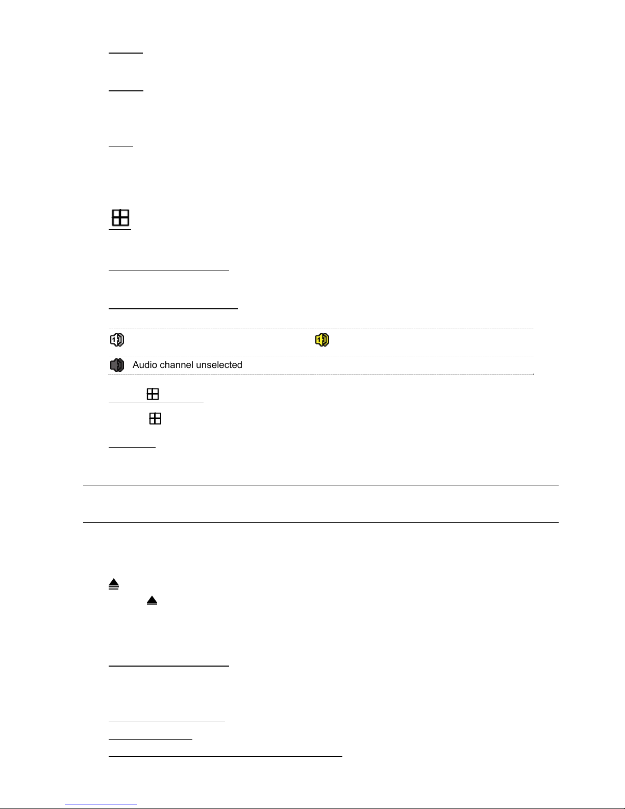
12) AUDIO (SLOW + ZOOM)
Press “SLOW” + “ZOOM” to select live or playback audio from audio channel 1~4.
Live audio from audio channel 1~4
(indicated in white)
Playback audio from audio channel 1~4
(indicated in yellow)
Audio channel unselected
13) P.T.Z. ( + SEQ)
Press “ ” + “SEQ” at the same time to enter / exit the PTZ control mode.
14) USB port
There are two USB ports on the front panel, one for connecting your USB mouse for
mouse control, and the other one for connecting your USB flash drive for video backup.
Note: It’s not allowed to have two USB mice or two USB flash drives connected on
the front panel.
For the compatible USB flash drive list, please refer to “APPENDIX 2 COMPATIBLE
USB FLASH DRIVE LIST” at page 67.
15) (For selected models only)
Press “
” to open / close the DVD writer.
1.3 Rear Panel
1) 75Ω / HI-IMPEDANCE (For Selected Models Only)
When using Loop function, please switch to HI-IMPEDANCE. When you don’t use Loop
function, please switch to 75Ω.
2) INPUT (1 ~ 16 / 1 ~ 8):
Connect to the video connector of a camera.
VIDEO IN (1 ~ 4): Connect to the video connector of a camera.
LOOP (1 ~ 16 / 1 ~ 8) (For Selected Models Only): Video output connector.

BEFORE USING THIS DVR
3
Note: The DVR will automatically detect the video system of the camera, please
make sure that the cameras are properly connected to the DVR and
power-supplied before the DVR is turned on.
3) AUDIO IN
Connect to the audio connector of a camera if the camera supports audio recording.
Note: To make a video backup with audio, make sure the camera which supports
the audio function is connected to the video-in channel and audio-in
channel. For example, the audio data from audio CH1 will be recorded with
the video data from video CH1.
4) AUDIO OUT
Connect to a speaker with 1 mono audio output.
Note: To know how many audio outputs your DVR supports, please refer to its
specifications.
5) MONITOR
Connect to a CRT monitor for video output.
6) CALL (For Selected Models Only)
Connect to a monitor specific for sequence display.
7) VGA
Connect to a LCD monitor directly.
8) HD Display (For Selected Models Only)
Connect to the port of the monitor which supports HD video output.
9) IR (For Selected Models Only)
Connect the optional IR receiver extension cable for remote control.
10) EXTERNAL I/O
This port is used to connect external devices (such as speed dome cameras or external
alarm, etc).
For detailed I/O port PIN configuration, please refer to “APPENDIX 6 PIN
CONFIGURATION” at page 72.
11) LAN
Connect to Internet by LAN cable.
12) DC IN
Connect to the supplied adapter.
13) Power Switch
Switch to “” to turn on the power, and “” to turn off the power.
CONNECTION AND SETUP
4
2. CONNECTION AND SETUP
Before the DVR is powered on, make sure you have installed a hard disk and connected
at least one camera. For details, please refer to the following sections.
Note: The DVR is designed to automatically detect the video system of the
connected cameras (NTSC or PAL). To make sure the system detection is
correct, please check if the cameras are connected to the DVR and
power-supplied before the DVR is powered on.
2.1 SATA HDD Installation
A SATA HDD must be installed before the DVR is powered on.
Note: It’s recommended to clear all data in the hard disk when the DVR is
powered on and the date & time are set correctly to ensure the recorded
data are not mixed with other data previously saved in the same hard disk.
For details, please refer to “5.7.6 Clear All HDD Data” at page 32.
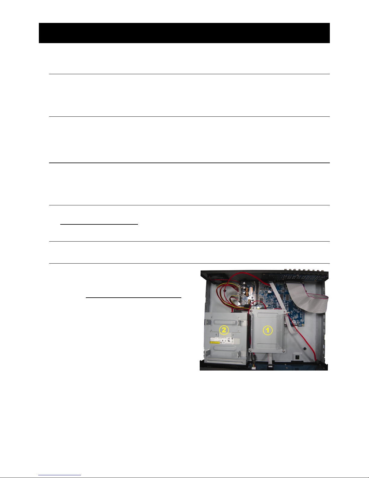
For 16CH & 8CH Models
Step1: Loose the screws on the upper cover and open the upper cover of the DVR.
Note: The DVR cover is made of metal. Please be careful with its edge when you
remove the cover.
Step2: There are two HDD brackets for this
DVR as indicated on the right picture.
2-1 To install on the first bracket
Remove the bracket, and align the
screw holes of the bracket with the
HDD’s screw holes. Make sure the
PCB side of the HDD is facing up.
Fasten the HDD to the bracket, and
connect the power connector and
data bus connector to the HDD.
Then, replace the bracket to DVR.
CONNECTION AND SETUP
5
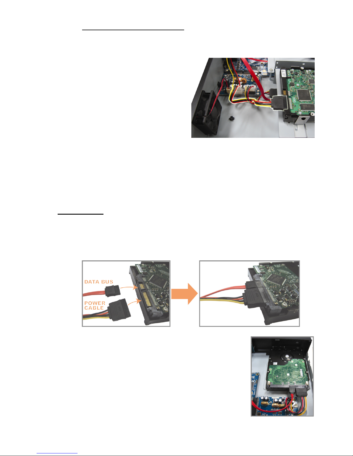
2-2 To install on the second bracket
Connect the power connector and
data bus connector to the HDD.
When connecting the power cable,
make sure the cable is passed
through the power cable of DVD
writer if your DVR is equipped with
a DVD writer. This is to prevent the
HDD power cable from interfering
with the fan spinning.
Align the screw holes of the bracket
with the HDD’s screw holes. Make
sure the PCB side of the HDD is
facing up. Then, fasten the HDD to
the bracket.
Step3: Close the upper cover of the DVR, and fasten all the screws you loosened in
Step1.
For 4CH Model
Step1: Loose the screws on the upper cover and remove it from the DVR. Find the hard
disk bracket located on the DVR base.
Step2: Get a compatible hard disk, and connect it to the power connector and data bus
connector.
Step3: Make sure the PCB side is facing up, and place the hard
disk between the hard disk bracket on the DVR base as
shown below.
Make sure the other side of the hard disk is
contacted with the DVR base for heat conduction.
CONNECTION AND SETUP
6
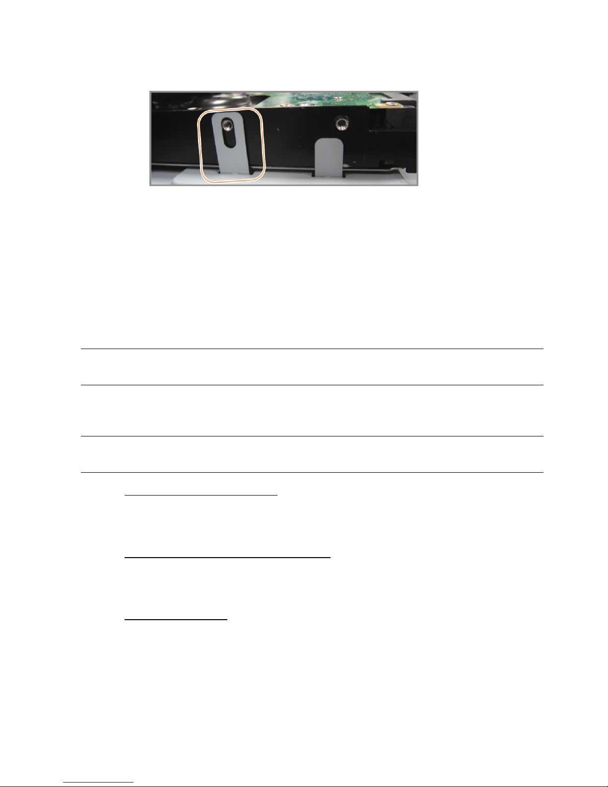
Step4: Align the screw hole on the each bracket with the screw hole on the each side of
the hard disk as shown below, and fix the hard disk to the bracket with a hard disk
screw supplied.
Step5: Close the upper cover of the DVR, and fasten all the screws you loosened in
Step1.
2.2 Camera Connection
The cameras must be connected and power-supplied before the DVR is powered on.
Connect the camera with the indicated power supply. Then, connect the camera video
output to the DVR video input port with a coaxial cable or RCA cable with BNC
connectors.
Note: For detailed DVR video input ports, please refer to “1.3 Rear Panel” at page
2.
2.2.1 Normal Camera Connection
Note: For detailed camera installation and connection, please refer to its own user
manual.
1) Connecting to DVR video input
Connect the camera video output to the DVR video input port with a coaxial cable or
RCA line with BNC connector.
2) Connecting to DVR audio input (Optional)
Connect the camera audio output to the DVR audio input port with a coaxial cable or
RCA cable with BNC connectors.
3) Connecting to power
Connect the camera with indicated power supply and make sure it’s power-supplied.
CONNECTION AND SETUP
7
2.2.2 PTZ Camera Connection
The following description is taking our brand’s PTZ camera as an example.
For DVR setting to control the PTZ camera, please refer to “5.6 PTZ Camera Setting” at
page 28. For detailed PTZ camera control and operation, please refer to its own user
manual.
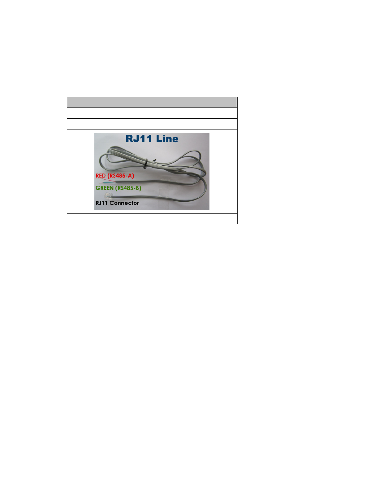
RJ11 cable
RS485-A: Red wire
RS485-B: Green wire
The RJ11 cable is not supplied in the sales package.
STEP 1: Get a RJ11 cable with the proper length to your connection.
Different RJ11 connector may have different wire layout, so the connection
might be different. If you cannot control the DVR after connection, please
reverse the RJ11 cable connection with the DVR.
STEP 2: Remove one end of the insulating coating of the RJ11 cable.
Remove one end of the insulating coating of the RJ11 cable to find the
RS485-A and the RS485-B wires, and remove the insulating coating to reveal
the naked wires for further connection.
STEP 3: Twist the RS485-A and RS485-B wires of the RJ11 cable and the speed
dome camera together.
Twist the RS485-A (red) and RS485-B (green) wires of the RJ11 cable to the
RS485-A (brown) and RS485-B (orange) wires of the speed dome camera. To
protect the naked wires, use the insulation tape to cover on the twisted wires.
STEP 4: Connect the other end of the RJ11 cable to DVR.
Solder the RS485-A (red) and RS485-B (green) wires of the RJ11 cable to the
corresponding pins on the solder side of the optional D-Sub connector.
For DVR PIN configuration, please refer to “APPENDIX 6 PIN
CONFIGURATION” at page 72. For connection details, please check with your
installer.

CONNECTION AND SETUP
8
STEP 5: Set the speed dome camera at the DVR side.
When the DVR is powered on, go to “ADVANCED CONFIG” “DEVICES” to
set the speed dome camera.
a) Select the device to “PTZ”.
b) Set the ID to the value the same as the one set in the speed dome camera.
The default ID of the camera is 000.
c) Select the protocol to “NORMAL”.
d) Set the baud rate to the value the same as the one set in the speed dome
camera. The default baud rate of the camera is 2400.
ADVANCED CONFIG
C AM E R A CH1 CH2 CH3 CH4 CH5 CH6 CH7 CH8 CH9 CH10 CH11
DETECTION DEVICE PTZ
ALERT ID 000
NETWORK PROTOCOL NORMAL
DISPLAY RATE 2400
RECORD
DEVICES
NOTIFY
EXIT
2.3 External Device Connection
This device supports external device connection with RS485 and alarm I/O ports,
allowing users to connect control devices such as a PTZ camera or keyboard controller,
or connect alarm devices such as a magnetic contact or buzzer.
Check the user manual of your external device to know which pin(s) should be used, and
connect it to the corresponding pins on the DVR rear panel.
Note: For more details about alarm I/O pin configurations, please refer to
“APPENDIX 6 PIN CONFIGURATION” at page 72.
Certain alarm-in pins also support sending instant event notifications to your mobile
devices, such as iPhone, iPad and Android mobile devices, for an alarm event (Push
Video). For details, please refer to “5.1 Push Video Configuration” at page 19.

CONNECTION AND SETUP
9
2.4 DVR Power On
This device should be operated only with the type of power source indicated on the
manufacturer’s label. Connect the indicated AC power cord to the power adapter, and
plug into an electrical outlet. Then, move the power switch to “” to power on the DVR.
Note: Before the DVR is powered on, make sure the cameras are connected and
power-supplied for the detection of the camera video system to be correct,
and check the monitor (either LCD or CRT monitor) is connected to the DVR
before the DVR is powered on for correct video output detection.
Note: To ensure that your DVR works constantly and properly, it's recommended
to use an UPS, Uninterruptible Power Supply (Optional), for continuously
operation.
2.5 Date and Time Setting
Before operating your DVR, please set the date and time on your DVR FIRST.
Note: Please DO NOT change the date or time of your DVR after the recording
function is activated. Otherwise, the recorded data will be disordered and
you will not be able to find the recorded file to backup by time search. If
users change the date or time accidentally when the recording function is
activated, it’s recommended to clear all HDD data, and start recording
again.
Note: For the first time to use the DVR, please power it on for at least 48 hours
continuously after the date & time is set correctly. It helps to prevent DVR
time from resetting after the disconnecting of DVR power. If the DVR time
resets after the disconnecting of DVR power, for example, caused by a
power outage, the battery might run out and please replace the battery as
described in “APPENDIX 5 DVR BATTERY REPLACEMENT” at page 71.
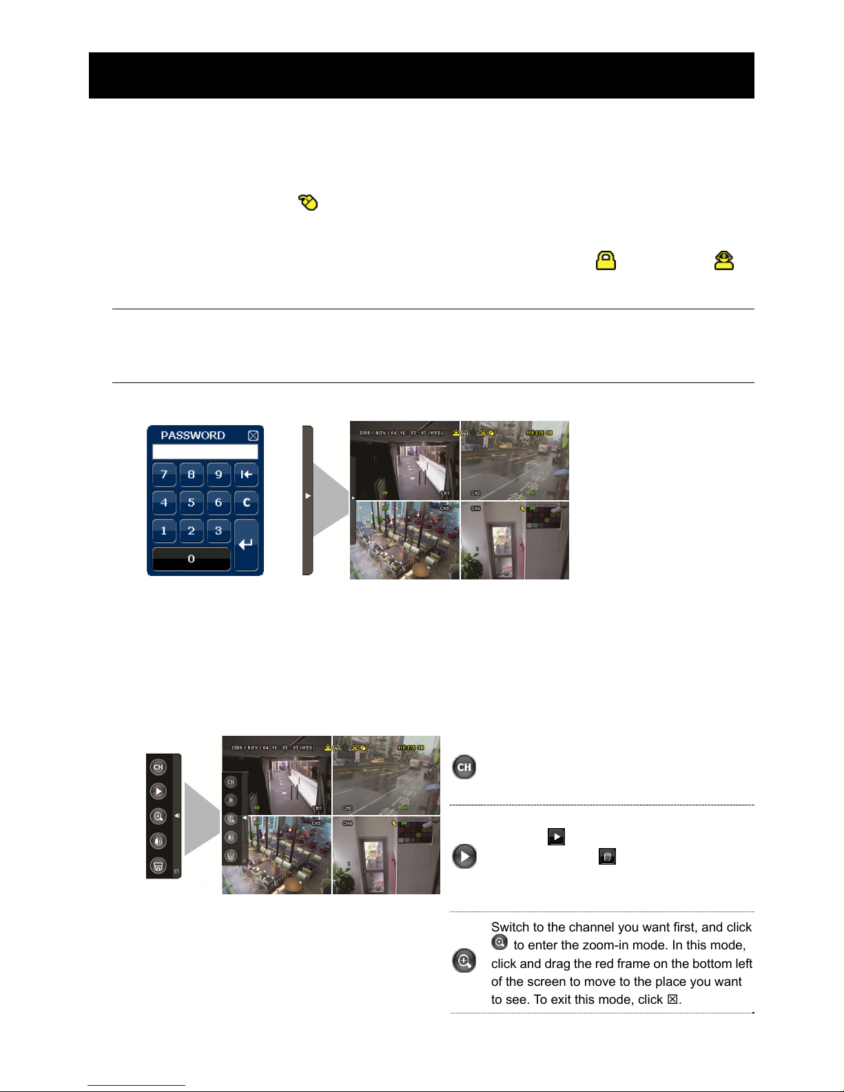
Right-click to enter the DVR password with the password keypad. The default
administrator password is 0000. The status will be changed from (key lock) to
(administrator). Then, right-click to show the main menu, and select “QUICK START”
“TIME SETUP” to set the date & time.

CONNECTION AND SETUP
10
QUICK START
GENERAL
DATE 2009 / NOV / 17
TIME SETUP
TIME 15 : 35 : 53
EXIT
2.6 Clear Hard Disk
It’s recommended to clear all data in the hard disk for the first time to user this DVR to
ensure the recorded data are not mixed with other data previously saved in the same
hard disk.
Right-click to show the main menu, and select “SYSTEM” “SYSTEM INFO”
“CLEAR HDD”. The DVR will reboot when HDD data are cleared.
SYSTEM
ACCOUNT BAUD RATE 2400
TOOLS HOST ID 000
SYSTEM INFO R.E.T.R (For Selected Models Only) 5
BACKUP DATA (USB) AUTO KEY LOCK NEVER
BACKUP LOG (USB) CLEAR HDD HDD-0
RESET DEFAULT SUBMIT
REMOTE CONTROL ID 000
SERIAL TYPE RS485
VIDEO FORMAT NTSC
VERSION 1025-1011-1011-1012
EXIT
2.7 Password Setting
Right-click to show the main menu, and select “SYSTEM” “TOOLS” to change the
DVR password.
There are two user levels: ADMIN & OPERATOR. For details, please refer to “4.4 User
Level Switch” at page 17.

CONNECTION AND SETUP
11
SYSTEM
ACCOUNT LANGUAGE ENGLISH
TOOLS ADVANCED LOGIN YES
SYSTEM INFO ADMIN PASSWORD SETUP
BACKUP DATA (USB) OPERATOR PASSWORD SETUP
BACKUP LOG (USB) UPGRADE SUBMIT
BACKUP CONFIG SUBMIT
RESTORE CONFIG SUBMIT
EXIT
GUI DISPLAY WITH USB MOUSE CONTROL
12
3. GUI DISPLAY WITH USB MOUSE CONTROL
3.1 Connect USB Mouse
Connect your USB mouse to one of the USB ports on the DVR front panel, and check if
there’s a mouse icon ( ) on the screen, indicating the USB mouse is detected properly.
Move your mouse to enter the DVR password with the password keypad. The default
administrator password is 0000. The status will be changed from (key lock) to
(administrator), and the quick menu bar appears on the left side of the screen.
Note: There are two user levels for DVR access which can be set in the main menu
“SYSTEM” “TOOLS”. For details, please refer to “4.4 User Level Switch” at
page 17.
Password Input Quick Menu: Close
3.2 Quick Menu Bar
Move to the arrow mark to extend the quick menu bar and show the five functions as
follows:
Quick Menu: Open
Click to show the channel switch panel and
select the channel you want. For details,
please refer to “3.2.1 Channel Switch” at
page 13.
Click to display the playback control panel,
and click
to play the latest recorded
video clip, or click
to enter the search list.
For details, please refer to “4.3 Playback” at
page 16.
Switch to the channel you want first, and click
to enter the zoom-in mode. In this mode,
click and drag the red frame on the bottom left
of the screen to move to the place you want
to see. To exit this mode, click .
GUI DISPLAY WITH USB MOUSE CONTROL
13
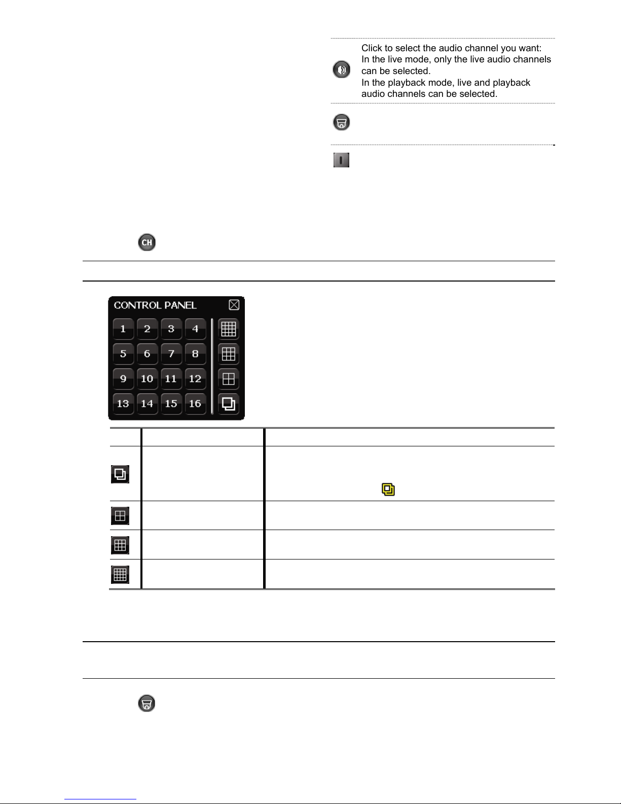
Click to select the audio channel you want:
In the live mode, only the live audio channels
can be selected.
In the playback mode, live and playback
audio channels can be selected.
Click to enter the PTZ mode and show the
PTZ camera control panel. For details, please
refer to “3.2.2 PTZ Control Panel” at page 13.
Click to show the power off panel to either
halt or reboot the system.
3.2.1 Channel Switch
Click on the quick menu bar to display the panel as follows:
Note: The buttons available depend on the model you have.
1~16 Video Channel Number
Click to switch to the channel you want in full screen.
Sequence Display
Click to display each channel in full screen one by one starting
from CH1. When the last channel is displayed, it will repeat from
CH1 again.
When this function is on,
will be shown on the status bar.
Quad Display
Press to show the 4-channel display mode.
9-Cut Display
Press to show the 9-channel display mode.
16-Cut Display
Press to show the 16-channel display mode.
3.2.2 PTZ Control Panel
Note: In the PTZ control mode, hot point is supported to move the camera view to
the specified point after a click.
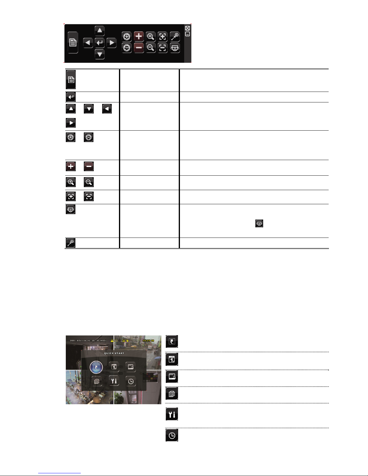
Click on the quick menu bar to display the panel as follows:
GUI DISPLAY WITH USB MOUSE CONTROL
14
Camera Menu
Click to enter the camera main menu.
For details about each camera menu, please refer to its
own user manual.
Enter
Click to confirm your selection / enter the menu.
/ / /
Up / Down / Left /
Right
Click to move your selection up / down / left / right, or
change settings.
/
Iris + / Iris -
This two buttons are designed for the PTZ camera
which uses Pelco-D to control. To know the actions after
clicking Iris + and Iris -, please refer to the camera’s
user manual.
/
Zoom in / out max
Click to zoom in on the image to the largest / zoom out
on the image to its original size.
/
Zoom in / out
Click to zoom in / out the image.
/
Focus near / far
Click to adjust the focus of the image.
Auto mode
Click to activate the auto function.
Before using it, you need to assign a specific function
that will be enabled when “
” is clicked. For details,
please refer to the user manual of the PTZ camera.
Preset point
Click to enter the PTZ preset point you want to see.
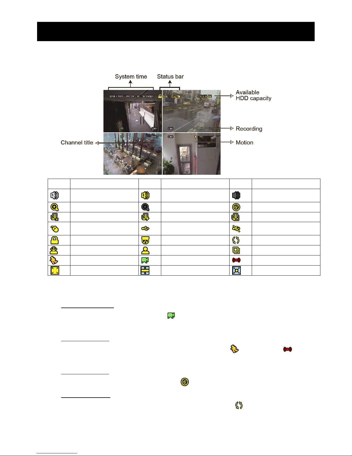
3.3 Main Menu
Right-click anywhere on the screen to show the main menu as follows, and right-click
again to exit.
For details about the menu structure, please refer to “APPENDIX 4 MAIN MENU
STRUCTURE” at page 69.
Main Menu
QUICK START
Click to set the status display, image
settings, and date & time.
DATE SETUP
Click to set the date display and
daylight saving.
SYSTEM Click to set the system configurations.
EVENT
INFORMATION
Click to enter the event search menu.
ADVANCED
CONFIG
Click to set CAMERA, DETECTION,
ALERT, NETWORK, DISPLAY,
RECORD, DEVICES & NOTIFY.
SCHEDULE
SETTING
Click to set record timer, detection
timer & alarm timer.
.
BASIC OPERATION
15
4. BASIC OPERATION
4.1 Live Page
Icon Function Icon Function Icon Function
Live audio channel (1~4)
Playback audio channel
(1~4)
Audio channel off
Digital zoom on
Digital zoom off
Timer recording
Network disconnected
Internet connected
LAN connected
USB mouse connected
USB flash drive / device
connected
No USB device
connected
Key lock
PTZ mode on
HDD overwrite
Administrator
Operator
Sequence
Motion
Recording
Alarm
Record mode: Frame
Record mode: Field
Record mode: CIF
4.2 Record Icon
1) Manual Recording
By defaults, manual recording is on ( ) when the DVR is powered on and a HDD is
installed.
2) Event Recording
When the motion detection or alarm is on, the motion icon ( ) or alarm icon ( ) shows
on the screen for any motion or alarm event.
3) Timer Recording
When timer recording is on, you will see “ ” on the screen.
4) HDD Overwritten
Be defaults, the HDD overwritten function is set to ON, and “ ” will be shown on the
screen.
BASIC OPERATION
16
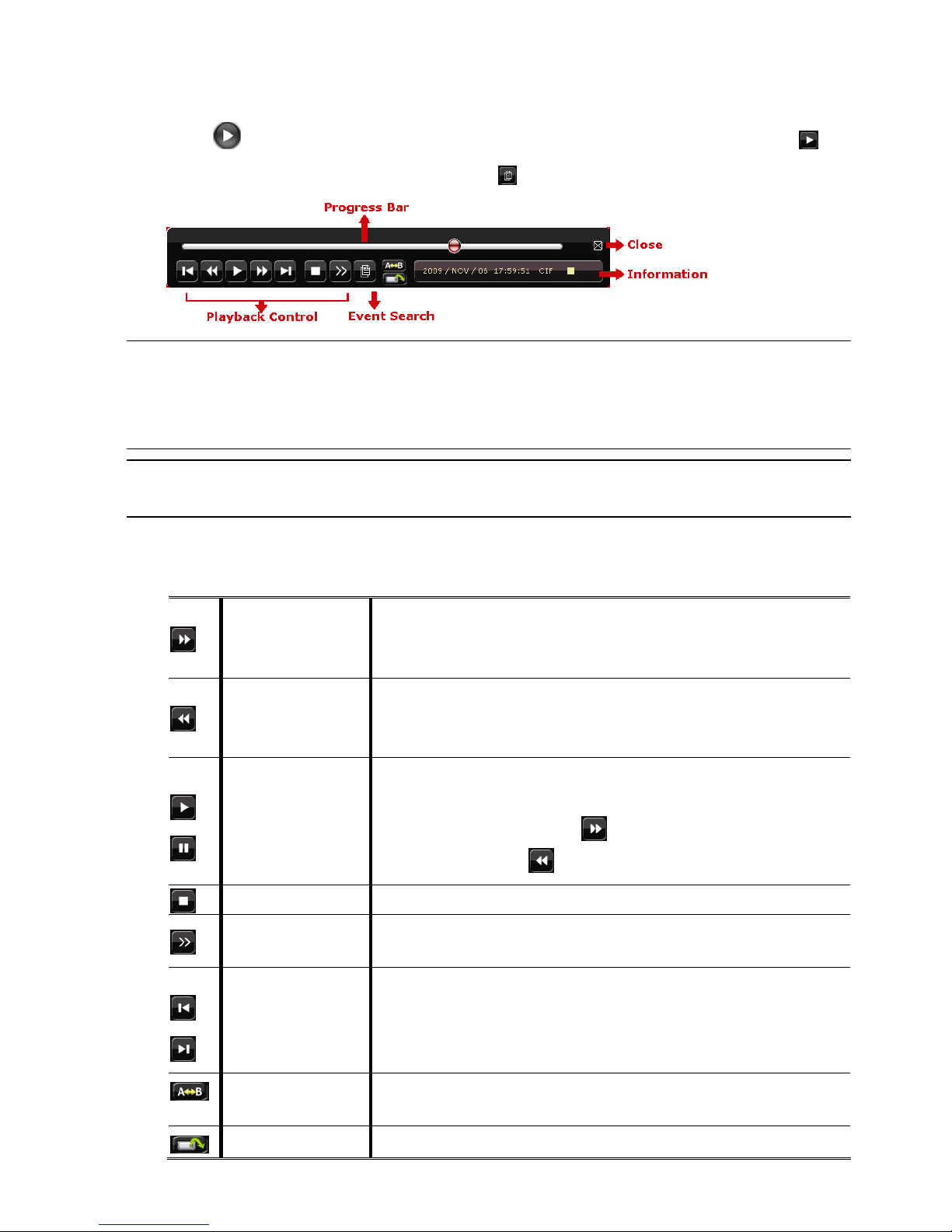
4.3 Playback
Click “ ” on the quick menu bar to display the playback control panel, and click to
play the latest recorded video clip, or click to enter the search list.
Note: There must be at least 8192 images of recorded data for playback to work
properly. If not, the device will stop playback. For example, if the IPS is set
to 30, the recording time should be at least 273 seconds (8192 images / 30
IPS) for the playback to work properly.
Note: During playback, the image size of the recording (FRAME, FIELD or CIF) will
be shown on the screen.
4.3.1 Playback Control
Fast Forward
Increase the speed for fast forward. Click once to get 4X
speed forward and click twice to get 8X speed, etc., and
the maximum speed is 32X.
Fast Rewind
Increase the speed for fast rewind. Click once to get 4X
speed rewind and click twice to get 8X speed, etc., and the
maximum speed is 32X.
/
Play / Pause
Click to play the latest recorded video clip immediately,
and click again to pause.
In the pause mode, click once to get one frame
forward, and click to get one frame rewind.
Stop
Click to stop the video playback.
Slow Playback
Click once to get 1/4X speed playback, and click twice to
get 1/8X speed playback.
/
Previous /
Next Hour
Click to jump to the next / previous time interval in an hour,
for example, 11:00 ~ 12:00 or 14:00 ~ 15:00, and start
playing the earliest event video clip recorded during this
whole hour.
Repeat
Click to set point A and point B in a video clip, and the
system will play only the specified range in that clip.
Backup Click to open the backup menu for video backup.
BASIC OPERATION
17
4.3.2 Event Search
Click to quickly search the recorded files by event lists: RECORD / MOTION /
ALARM / TIME, or select FULL to show all the event logs.
To quickly search the time you want, select “QUICK SEARCH”. Set the time range you
want, and select “SUBMIT” to play the recorded video clip during the specified time.
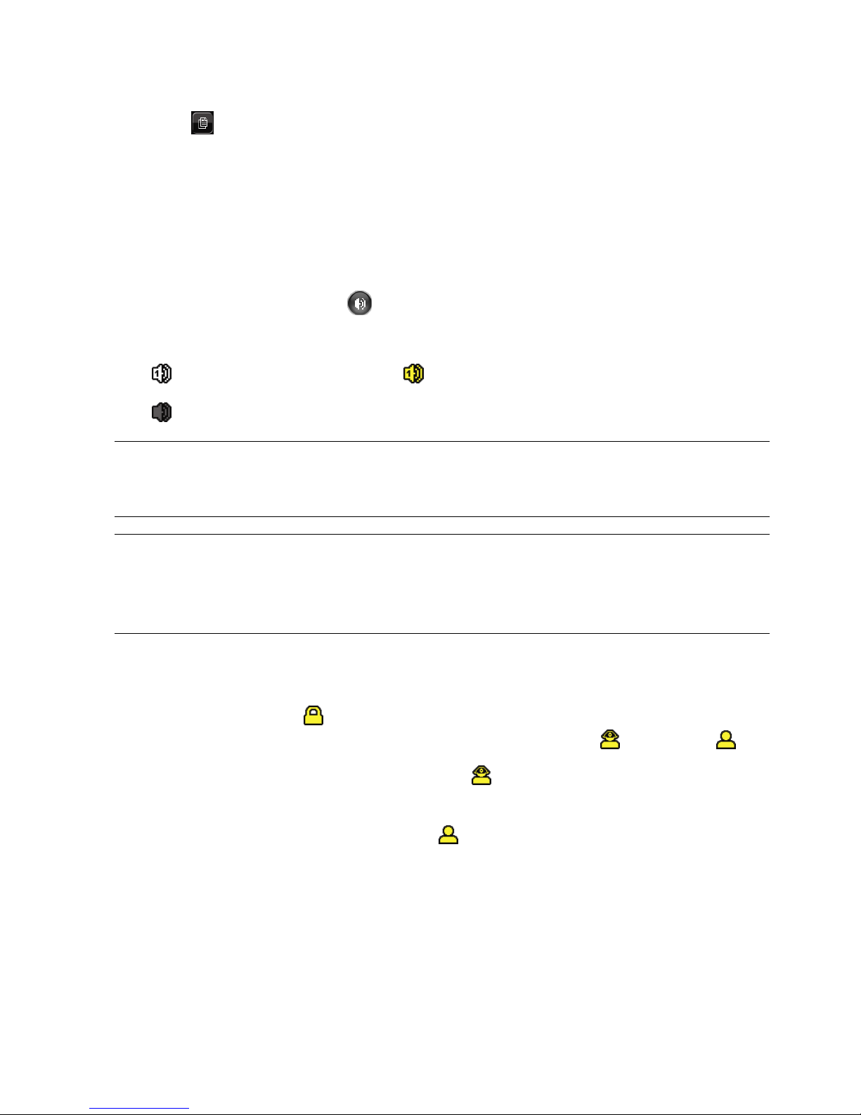
4.3.3 Audio Playback
In the playback mode, click on the quick menu bar as many times as needed to
select live or playback audio from audio channel 1~4.
Live audio from audio channel 1~4
(indicated in white).
Playback audio from audio channel 1~4
(indicated in yellow).
Audio channel unselected
Note: For 4CH models, “VGA OUTPUT” appears only when “PRIORITY” is set to
“DISPLAY FIRST”. For details, please refer to “4.5 System Sources
Reallocation (For 4CH Models Only)”.
Note: To make a video backup with audio, make sure the camera which supports
the audio function is connected to the video-in channel and audio-in
channel. For example, the audio data from audio CH1 will be recorded with
the video data from video CH1.
4.4 User Level Switch
In the key lock mode ( ), move your USB mouse to display the password input keypad.
There are two user levels for accessing the DVR: Administrator ( ) & Operator ( ).
When the administrator password is entered, will be shown on the status bar of the
screen and all operations are allowed. The default administrator password is 0000.
When the operator password is entered, will be shown on the status bar of the
screen, and the main menu is NOT allowed to access. The operator user level needs to
be set in the main menu “SYSTEM” “TOOLS”.
To switch between these two user levels, click the current user level icon to switch to the
key lock mode, and move your mouse to show the password input keypad, and enter the
password of the user level you want.

BASIC OPERATION
18
4.5 System Sources Reallocation (For 4CH Models Only)
Go to “QUICK START” “GENERAL”, and select “PRIORITY” to reallocate the system
sources to live display and record.
There are two options for this function: RECORD FIRST / DISPLAY FIRST / NETWORK
FIRST.
QUICK START
GENERAL
CHANNEL TITLE ON
TIME SETUP
EVENT STATUS ON
DATE DISPLAY ON
MOUSE SENSITIVITY - ׀ ׀ ׀ ׀ ׀ ׀ ׀ ׀ ׀ +
PRIORITY (For 4CH Models Only) RECORD FIRST
RECORD CONFIG SETUP
EXIT
RECORD FIRST: When this option is selected, Full D1 at real-time record on all
channels is available, and the VGA output resolution is fixed to
1024 x 768.
DISPLAY FIRST: When this option is selected, three VGA output resolutions will be
available to choose), but Full D1 real-time recording on all
channels will not be available.
For models supporting HD video output, the options are
AUTO (default) / 1024 x 768 / 1920 x 1080.
For others, the options are 1024 x 768 / 1280 x 1024 / 1600 x 1200.
NETWORK FIRST: When this option is selected, real-time remote monitoring will be
available, but Full D1 real-time recording on all channels will not
be available, and the VGA output resolution is fixed to 1024 x 768.

FREQUENTLY-USED FUNCTIONS
19
5. FREQUENTLY-USED FUNCTIONS
5.1 Push Video Configuration
This DVR supports sending instant event notifications to your mobile devices, such as
iPhone, iPad and Android mobile devices, for an alarm event (Push Video). However,
only certain alarm-in pins support this function. For details, please check the instructions
below.
5.1.1 PIN Connection
An I/O board might be supplied with this DVR to help you quickly know which pin
supports Push Video, or you may refer to the table below, or refer to “APPENDIX 6 PIN
CONFIGURATION" at page 72.
Models without HD video output
PIN Corresponding
video channel
16CH Model PIN2 CH1
PIN15 CH2
PIN3 CH3
PIN16 CH4
8CH Model PIN2 CH1
PIN15 CH2
4CH Model PIN1 CH1
Models with HD video output
PIN Corresponding
video channel
PIN6 CH1 With 9-pin I/O
block
PIN7 CH2
PIN8 CH3
PIN9 CH4
PIN6 CH1 With 7-pin I/O
block
PIN7 CH2
With 6-pin I/O
block
PIN6 CH1
FREQUENTLY-USED FUNCTIONS
20
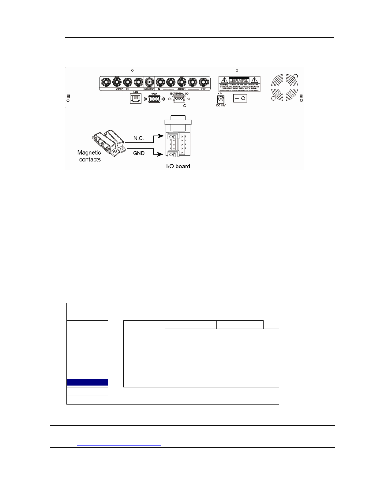
Alarm sensor connection: take 4CH model without HD video output as an example
Connect the alarm sensor, such as magnetic contacts, to the I/O pin which supports
Push Video.
A2.2 Configuration
Before configuring Push Video, make sure:
1. The DVR system is set up as described in “3. CONNECTION AND SETUP”.
2. The DVR is connected to Internet.
3. You’ve installed the app, EagleEyes, on your iPhone, iPad or Android mobile devices.
For details, please refer to “APPENDIX 7 MOBILE SURVEILLANCE VIA EAGLEEYES” at
page 79.
Step1: Right click to show the main menu.
Go to “ADVANCED CONFIG.” " NOTIFY” to enable “GUARD” to “ON”, and
configure your alarm sensor type (N.C. or N.O.).
ADVANCED CONFIG
CANERA
PUSH VIDEO
MESSAGE MAIL VIDEO MAIL
DETECTION
GUARD ON
ALERT
CH01 ALARM N.O. CH1
NETWORK
DISPLAY
RECORD
DEVICES
NOTIFY
EXIT
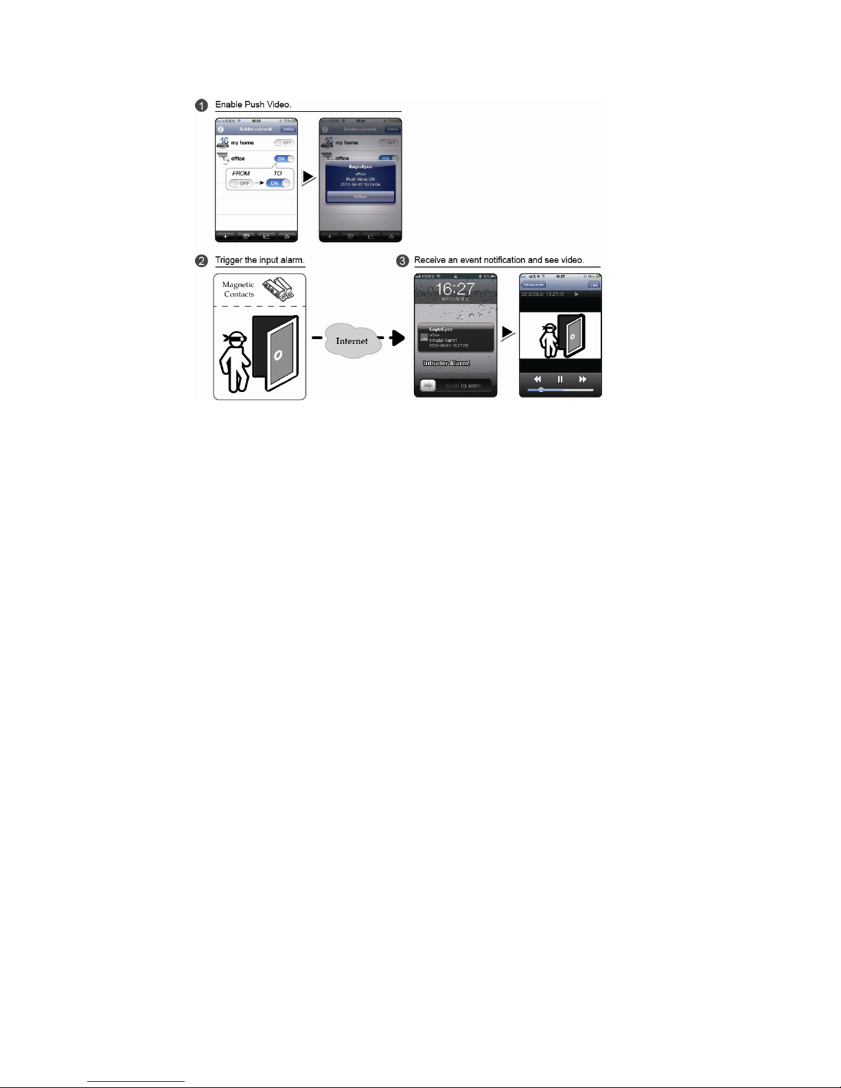
Step2: Open EagleEyes, and add this DVR to the EagleEyes address book.
Note: For more details about EagleEyes operation, please visit
www.eagleeyescctv.com.
FREQUENTLY-USED FUNCTIONS
21
Step3: Enable Push Video as described below, and try to trigger your sensor to see if
you can receive Push Video successfully.
 Loading...