

Page 1
WGD00071
Page 2

WatchGuard DV-1 User Guide
Copyright © 2014 WatchGuard Video
All rights reserved.
WatchGuard and DV-1 are trademarks of WatchGuard Video.
All other marks, names, and logos mentioned herein are the
property of their respective owners.
Enforcement Video LLC is a Texas Limited Liability Company
doing business as WatchGuard Video.
WatchGuard Video
415 Century Parkway
Allen, Texas 75013
1-800-605-6734 Toll Free Sales
1-866-384-8567 Toll Free Support
This document is applicable to DV-1 Firmware Version 7.0 and
above.
SAFETY WARNINGS
To prevent fire or shock hazard, do not expose the DV-1 unit
to rain or moisture.
To avoid electrical shock, do not disassemble the DV-1
housing or place any objects other than the DVD inside the
system. Refer servicing to qualified personnel only.
The use of optical instruments with the DV-1 product will
increase eye hazard. As the laser beam used in the DVD
drive is harmful to eyes, do not attempt to disassemble the
DVD drive. Refer servicing to qualified personnel only.
Should any solid object or liquid fall into the DV-1 unit,
disconnect the unit from power and have it checked by
qualified personnel before further operation.
2
Page 3

Table of Contents
1 Introduction to WatchGuard Video ........................................................................................... 7
1.1 Welcome Statement and Company Values ................................................................................................................... 7
1.2 Notices, Cautions, and Warnings ................................................................................................................................... 7
1.3 Using This Document..................................................................................................................................................... 8
1.4 Please Give Us Your Suggestions ................................................................................................................................. 8
1.5 DV-1 Firmware Updates ................................................................................................................................................ 9
1.6 DV-1 Hardware Versions ............................................................................................................................................... 9
1.7 DV-1 Technical Specifications ..................................................................................................................................... 10
1.8 Manufacturer Contact Information ............................................................................................................................... 10
1.9 Related Documents ..................................................................................................................................................... 10
2 Safety, Product Care, and Warranty ...................................................................................... 11
2.1 Important Safety Instructions ....................................................................................................................................... 11
2.2 Driver’s Safety ............................................................................................................................................................. 11
2.3 Installation Cautions..................................................................................................................................................... 11
2.4 Post-Installation Cautions ............................................................................................................................................ 12
2.5 Modification Warning ................................................................................................................................................... 12
2.6 Proper Disposal ........................................................................................................................................................... 12
2.7 Maintenance Responsibilities ...................................................................................................................................... 12
2.8 Recording Failure Compensation ................................................................................................................................ 12
2.9 Warranty ...................................................................................................................................................................... 13
2.9.1 Limited One (1)-Year Warranty...................................................................................................................... 13
2.10 Owner’s Record ........................................................................................................................................................... 14
3 DV-1 System Overview.......................................................................................................... 15
3.1 DV-1 System Description ............................................................................................................................................. 15
3.2 Accessories and Input Devices .................................................................................................................................... 16
3.3 Software Utilities .......................................................................................................................................................... 16
3.4 Permission Levels ........................................................................................................................................................ 17
3.5 Connections and Cable Diagrams ............................................................................................................................... 18
3.6 Front Panel Controls .................................................................................................................................................... 20
3.7 Front Camera Keypad.................................................................................................................................................. 21
3.8 DVD Status Icons ........................................................................................................................................................ 21
4 DV-1 Configuration ................................................................................................................ 23
4.1 Main Menu Access ...................................................................................................................................................... 23
4.2 Fleet Manager Utility .................................................................................................................................................... 24
4.3 Set Department Name ................................................................................................................................................. 24
4.4 Set Vehicle ID ................................ ................................................................ ................................ .............................. 25
4.5 Manage Officer Names ................................................................................................................................................ 26
4.5.1 Add Officer..................................................................................................................................................... 26
4.5.2 Edit Officer ..................................................................................................................................................... 27
4.5.3 Delete Officer................................................................................................................................................. 28
4.6 Setup Input Devices ..................................................................................................................................................... 29
4.6.1 Radar Setup .................................................................................................................................................. 30
4.6.2 Fan Speed ..................................................................................................................................................... 30
4.6.3 Lights, Siren, and Brake Lights ...................................................................................................................... 31
4.6.4 GPS Setup..................................................................................................................................................... 32
4.6.5 Temperature Sensor ...................................................................................................................................... 33
4.6.5.1 Adjusting the Calibration .............................................................................................................. 33
4.7 Recording Setup .......................................................................................................................................................... 34
4.7.1 Pre- and Post-Event Recording ..................................................................................................................... 34
4.7.1.1 Set Pre-Event Time ..................................................................................................................... 34
4.7.1.2 Set Post-Event Time .................................................................................................................... 35
4.7.2 Auto-Record Trigger Setup ............................................................................................................................ 36
4.7.2.1 Setup START Triggers ................................................................................................................ 36
4.7.2.2 Setup STOP Triggers .................................................................................................................. 38
3
Page 4

4.7.3 Set Video Quality ........................................................................................................................................... 39
4.7.4 Set the Auto-Zoom......................................................................................................................................... 39
4.7.5 Manage On-Screen Text ............................................................................................................................... 40
4.7.5.1 Display On-Screen Text in the Vehicle ........................................................................................ 41
4.7.5.2 Display Disc Usage ...................................................................................................................... 41
4.7.5.3 Set Text Fields to Record ............................................................................................................ 42
4.8 Save or Restore Officer Preferences ........................................................................................................................... 43
4.8.1 Save Officer Preferences as Department Default .......................................................................................... 43
4.8.2 Restore Officer Preferences .......................................................................................................................... 44
5 Detailed DV-1 Operation ........................................................................................................ 45
5.1 About DVD Media ........................................................................................................................................................ 45
5.2 Select Officer ............................................................................................................................................................... 45
5.3 Ejecting a DVD ............................................................................................................................................................. 46
5.4 Video Review Mode ..................................................................................................................................................... 47
5.4.1 Review the Most Recent Video on the Hard Drive ......................................................................................... 47
5.4.2 Show/Hide Menu ........................................................................................................................................... 47
5.4.3 Video Control Keys ........................................................................................................................................ 48
5.4.4 View Previously Recorded Events ................................................................................................................. 48
5.4.5 Define a New Event Start/Stop (Record After the Fact) ................................................................................. 49
5.5 Recording to DVD ................................ ................................................................ ........................................................ 50
5.5.1 Stop Recording .............................................................................................................................................. 51
5.5.2 Automatic Event Segmentation ..................................................................................................................... 51
5.5.3 Scenarios Where DVD Burning is Halted ...................................................................................................... 52
5.5.4 Disc Usage Meter .......................................................................................................................................... 52
5.5.5 Automatic Disc Overflow Recording .............................................................................................................. 54
5.5.6 Covert Mode .................................................................................................................................................. 55
5.6 Split-Screen Display ..................................................................................................................................................... 55
5.7 Closed-Captioning Text on DVD Playback................................................................................................................... 56
5.7.1 DVD Manager Utility (DMU) ........................................................................................................................... 56
5.8 Front Panel Controls .................................................................................................................................................... 57
5.8.1 Display Key .................................................................................................................................................... 57
5.8.1.1 Dark Mode ................................................................................................................................... 57
5.8.1.2 Screen Saver ................................................................ ................................ ............................... 58
5.8.2 Volume Key ................................................................................................................................................... 60
5.8.3 Camera Key ................................................................................................................................................... 61
5.9 Front Camera Keypad Controls ................................................................................................................................... 62
5.9.1 Back Light Compensation .............................................................................................................................. 62
5.9.2 Night View ..................................................................................................................................................... 63
5.9.3 Auto-Zoom ..................................................................................................................................................... 64
5.9.4 Zoom (Manual) .............................................................................................................................................. 64
5.9.5 Auto-Focus .................................................................................................................................................... 65
5.9.5.1 Manually Setting Focus................................................................................................................ 65
5.10 Playback on Computers and DVD Players................................................................................................................... 66
5.10.1 Software Programs for Playback ................................................................................................................... 66
6 Cabin and Wireless Microphones .......................................................................................... 69
6.1 Microphone Menu ........................................................................................................................................................ 69
6.2 Wireless Microphone Synchronization ......................................................................................................................... 69
6.3 Lapel Microphone Placement ................................................................................................................................ ....... 70
7 System Status Information Screens ....................................................................................... 71
7.1 Status Information Overview ........................................................................................................................................ 71
7.2 DVD Disc, drive, and media information ...................................................................................................................... 71
7.3 Hard Drive Information ................................................................................................................................................. 73
7.4 System Information ...................................................................................................................................................... 74
7.5 User Information .......................................................................................................................................................... 74
7.6 Device Information ....................................................................................................................................................... 75
4
Page 5

8 Supervisor/Administrator Functions ....................................................................................... 77
8.1 Supervisor/Administrator Overview .............................................................................................................................. 77
8.2 Supervisor and Administrator Login ............................................................................................................................. 78
8.3 Set System Behavior ................................................................................................................................................... 78
8.3.1 Set Shutdown Delay ................................................................................................ ...................................... 79
8.4 Set Microphone Behavior ................................................................................................................................ ............. 80
8.5 Manage Permissions for Settings ................................................................................................................................ 80
8.5.1 Video Review Access Levels ......................................................................................................................... 82
8.6 Manage DVD and Hard Drive ...................................................................................................................................... 82
8.6.1 Format DVD................................................................................................................................................... 82
8.6.2 Check Hard Drive for Errors .......................................................................................................................... 83
8.6.3 Remove Configuration (Names, Settings, etc.).............................................................................................. 84
8.6.4 Reset Recording State .................................................................................................................................. 85
8.6.5 Set Number of DVDs to Backup .................................................................................................................... 86
8.6.6 Burn DVD from Backup ................................................................................................................................. 87
8.7 Manage Supervisor Passwords ................................................................................................................................... 88
8.7.1 Add Supervisor PIN ................................................................................................ ....................................... 89
8.7.2 Edit Supervisor PIN ....................................................................................................................................... 90
8.7.3 Delete Supervisor PIN ................................................................................................................................... 91
8.8 Updating DV-1 Firmware ............................................................................................................................................. 92
8.8.1 Troubleshooting a DV-1 Firmware Update .................................................................................................... 94
8.8.1.1 Unit Hangs at the DV-1 Splash Screen ........................................................................................ 94
8.8.1.2 Unit Remains Powered Off On a Reboot ..................................................................................... 95
9 Fleet Manager Utility .............................................................................................................. 97
9.1 Fleet Manager Utility Overview .................................................................................................................................... 97
9.2 Event Tags ................................................................................................................................................................... 97
9.2.1 Adding an Event Tag ..................................................................................................................................... 98
9.2.2 Editing an Event Tag ..................................................................................................................................... 99
9.3 Factory Default Settings ............................................................................................................................................. 102
10 Troubleshooting ................................................................................................ ................... 107
10.1 DVD Write Errors ....................................................................................................................................................... 107
10.2 Reuse the Current DVD ............................................................................................................................................. 107
10.3 Soft System Errors ..................................................................................................................................................... 107
10.4 System Temperature Issues ...................................................................................................................................... 108
10.4.1 DVD Drive Temperature Range................................................................................................................... 108
10.5 Hard Drive Quick Format ........................................................................................................................................... 109
10.5.1 Format Hard Drive to Maximum Capacity .................................................................................................... 111
10.6 Hard Drive Full Format............................................................................................................................................... 113
10.7 DV-1 Back Door Maintenance Options ...................................................................................................................... 114
10.7.1 Network Configuration ................................................................................................................................. 115
10.7.2 Setting the Locale ........................................................................................................................................ 116
10.8 Installation Problems.................................................................................................................................................. 116
10.9 Power-Related Issues ................................................................................................................................................ 116
10.9.1 System Resets or Hangs on Vehicle Start ................................................................................................... 116
10.9.2 Auto Power-Up/Power-Down Not Working .................................................................................................. 116
10.9.3 System Stalls During Boot-Up ..................................................................................................................... 116
11 Quick Start Guide ................................................................................................................ 117
11.1 Turning the DV-1 On & Off ......................................................................................................................................... 117
11.2 Set Time and Date ..................................................................................................................................................... 117
11.3 Insert DVD ................................................................................................................................................................. 118
11.4 Blank Disc Detected................................................................................................................................................... 118
11.5 Reuse a DVD ............................................................................................................................................................. 119
11.6 Start Recording .......................................................................................................................................................... 119
11.7 Stop Recording .......................................................................................................................................................... 119
11.8 Ejecting a DVD .......................................................................................................................................................... 119
11.9 Disc Usage Meter ...................................................................................................................................................... 120
11.10 Front Camera Keypad................................................................................................................................................ 121
5
Page 6

11.11 Video Review Mode ................................................................................................................................................... 121
11.11.1 Show/Hide Menu ......................................................................................................................................... 122
11.11.2 Video Control Keys ...................................................................................................................................... 122
11.12 Camera Overview ................................ ................................................................ ...................................................... 123
11.13 Front Panel Controls .................................................................................................................................................. 123
11.13.1 Select Camera ............................................................................................................................................. 123
11.13.2 Display/Front Panel Brightness ................................................................................................................... 124
11.13.3 Microphones ................................................................................................................................................ 124
11.13.4 Volume Control ............................................................................................................................................ 125
11.14 DVD Disc Information ................................................................................................................................................ 126
12 Other Modes of Operation ................................................................................................... 127
12.1 Loaner/Advanced Replacement Mode ....................................................................................................................... 127
12.1.1 Extend Loaner/Advanced Replacement Mode Time.................................................................................... 128
12.1.2 Unlock Loaner/Advanced Replacement Mode ............................................................................................. 130
12.2 Evaluation Mode ........................................................................................................................................................ 131
12.2.1 Extend Evaluation Mode Time ..................................................................................................................... 132
12.2.2 Unlock Evaluation Mode .............................................................................................................................. 134
Glossary of Terms ........................................................................................................................ 135
Index ............................................................................................................................................ 137
Figures
Figure 1 Overhead Unit ............................................................................................................................................. 15
Figure 2 Modular Unit ............................................................................................................................................... 15
Figure 3 Connections and Cable Diagram – Overhead Unit .................................................................................... 18
Figure 4 Connections and Cable Diagram – Modular Unit ....................................................................................... 19
Figure 5 Front Panel Controls ................................................................................................................................... 20
Tables
Table 1 Overhead Unit Cable Descriptions ............................................................................................................. 18
Table 2 Modular Unit Cable Descriptions ................................................................................................................ 19
Table 3 Front Panel Controls ................................................................................................................................... 20
Table 4 Front Camera Keypad ................................................................................................................................ 21
Table 5 Video Quality Mode Guide .......................................................................................................................... 39
Table 6 Department Default Preferences .............................................................................................................. 102
Table 7 Department Default Policies ..................................................................................................................... 103
Table 8 Vehicle Default Preferences ..................................................................................................................... 105
6
Page 7
Thank you for choosing the WatchGuard Video DV-1, the world's first
in-car Direct-to-DVD Video system that records directly onto rewritable DVD-Video discs that play in regular DVD players. The
company was founded to bring the finest mobile law enforcement
technology to the market.
The WatchGuard DV-1 is the culmination of nearly 60 man-years of
engineering development. This sophisticated system performs real
time DVD-Video authoring in a mobile environment. The proprietary
computing platform employs a dual-drive architecture and optical
drive ruggedization techniques developed for U.S. fighter jets. No
company in this industry has invested more engineering capital, or
has been more aggressive in research and development than
WatchGuard Video. With seven patents pending, the WatchGuard
DV-1 represents the most advanced technology available in the
industry.
The management of WatchGuard Video places an emphasis on
developing individual character qualities essential for true success,
and the company is dedicated to maintaining a culture of service. Our
management staff is encouraged to practice servant-based
leadership within their groups with the knowledge that by serving
God, people are empowered to better serve each other. This
environment creates the framework for WatchGuard Video to
ultimately serve our customers in a manner that instills the highest
level of trust, confidence, and satisfaction.
NOTICE
Notices provide useful supplemental information that is pertinent
to the task being described. They may appear either before or
after the text to which they apply.
CAUTION!
Cautions describe critical information that, if ignored, could
result in damage to the DV-1, inoperability or degradation in
function, or injury to personnel. Cautions always appear before
the critical text to which they apply.
WARNING!
Warnings provide information pertaining to possible data loss.
7
Page 8

USING THIS DOCUMENT INTRODUCTION TO WATCHGUARD VIDEO
Use the DV-1 User Guide to configure, operate, and maintain an
installed overhead or modular DV-1 system.
Chapter 11 – Quick Start Guide on page 117 provides the basic
information necessary to begin using the DV-1 system.
Chapter 12 – Other Modes of Operation on page 127 provides basic
information about temporary DV-1 operating modes.
For other tasks not covered in this document, see Related
Documents on page 10.
The left side of each page usually contains:
Informational and procedural text
Graphical depictions of the buttons/menus used to perform
procedures
Notices, cautions, or warnings
The right side of each page usually contains the resulting screen, an
error message, or a success message. Once familiar with DV-1
operation, many of the tasks can quickly be spotted by glancing down
the left side of the document.
NOTICE
Anytime a key () is displayed, an Administrator PIN is required to
perform the steps.
We want to hear from you. Tell us about your experiences and how
you are using your DV-1. We will do our best to accommodate any
suggestions you may have in future firmware revisions and hardware.
U.S. customers, call Customer Service at 1-800-605-6734 or email us
at customerservice@watchguardvideo.com with your comments,
questions, and concerns. International customers, contact your local
distributor.
8
Page 9
INTRODUCTION TO WATCHGUARD VIDEO DV-1 FIRMWARE UPDATES
Most of the features of the WatchGuard DV-1 are based on the
software resident within your system (often called firmware). We are
committed to the continual testing and improvement of the DV-1
system firmware. Improvements and software updates for the DV-1
firmware are provided to your agency for the life of the product, when
available.
See Updating DV-1 Firmware on page 92 for further details.
The unit’s original versions are the DV-1A and the DV-1B. The DV-1A
and the DV-1B are mostly identical. The newer versions of the unit
are the DV-1C, DV-1D, and DV-1E. For version identification see the
serial number on the unit.
The DV-1C, DV-1D, and DV-1E provide the following additional
functionality to the DV-1A and DV-1B:
Combined power and I/O ports – One locking connector
provides more current-carrying ability for the unit.
Audio/visual (A/V) port – Used to transmit the analog audio and
video of the DV-1 to an external device (such as a television or
video server).
USB port – For future expansion of the unit.
Basic function control panel (BFCP) port – For future
expansion to connect the unit to a Windows application running
on a laptop computer.
Faster DVD burning speeds
Ability to reduce the current consumption when the unit is off
(< 5 mA)
Faster Ethernet speed
Increased reliability due to manufacturing improvements and
environmental enhancements
Ability to mute cabin and wireless microphones independently
The DV-1D also has the following feature:
Redesigned DVD drive carriage
o Reduced potential bladder damage
o Improved response to vibration
9
Page 10

DV-1 TECHNICAL SPECIFICATIONS INTRODUCTION TO WATCHGUARD VIDEO
The DV-1E also has the following features:
Added power protection circuit that guards against over voltage
and reverse voltage
Ability to operate down to 5V
Higher resolution LCD – More realistic video playback with
better colors
Lowest radiated emissions of any DV-1 type
Environmentally-responsible lead-free process on the main board
For the most current DV-1 technical specifications, go to
http://watchguardvideo.com/dv1/specs.
WatchGuard Video
Attn: Customer Service Department
415 Century Parkway
Allen, Texas 75013
1-800-605-6734
customerservice@watchguardvideo.com
Refer to http://watchguardvideo.com/support for the following
supporting documentation:
DV-1 Quick Reference Guide
Overhead System Installation Overview
Modular System Installation Overview
DV-1 Menu Navigation Guides (GUI)
Fleet Manager Utility (FMU) Getting Started Guide
DVD Manager Utility (DMU) Getting Started Guide
10
Page 11
Adhere to the following safety instructions while using the DV-1:
Do not use this device near water.
Clean only with a dry cloth.
Do not block any ventilation openings. Install in accordance with
the manufacturer’s instructions.
Do not install near any heat registers or other devices that produce
heat.
Only use attachments/accessories specified by the manufacturer.
Refer all servicing to qualified service personnel. Servicing is
required when the device has been damaged in any way:
o Power-supply cord or plug is damaged
o Liquid has been spilled on or into it
o Objects have fallen into the device
o Device has been exposed to rain or moisture
o Has been dropped
Take the following precautions while driving:
Comply with all local traffic rules and regulations.
The driver must not watch or operate the device or any component
thereof while driving. It may lead to distraction and cause an
accident.
Park the vehicle in a safe place to watch or operate the device.
Do not obstruct the field of view of the driver.
Do not install the device where it is:
Near heat sources (such as heater vents)
Exposed to rain or moisture
Exposed to excessive dust or dirt
Subject to excessive vibration
Near vehicle components that heat up over time such as hoses,
high current wires, and braking system components
Near other objects that obstruct air-flow to the openings and slots.
The device must have proper ventilation to prevent over-heating.
Obstructing the field of view of the driver.
11
Page 12

POST-INSTALLATION CAUTIONS SAFETY, PRODUCT CARE, AND WARRANTY
Take the following precautions after installing the DV-1:
Do not hang objects from the device.
Do not insert your hands, fingers or foreign objects into the device.
It may cause injury or damage to the device.
Take care not to bump your head against the device when in the
vehicle.
Keep small articles out of the reach of children.
If the system does not work, check the connections first. If
everything is in order, check the fuse.
If while under the warranty period, it is determined that the WatchGuard
Video system was internally changed, modified, or repair attempted,
the system warranty will become null and void.
To ensure environmental compliance, disposal of the DV-1 should be in
accordance with other electronic devices such as computers.
The DV-1 does not require scheduled maintenance when operated in
accordance with the instructions provided in this document.
WatchGuard Video is not liable and will not compensate for any lost
recordings or relevant losses, including when recordings are not made
due to reasons including recording failure, or when the contents of a
recording are lost or damaged as a result of DVD drive failure or repair
undertaken to the DVD drive.
12
Page 13

SAFETY, PRODUCT CARE, AND WARRANTY WARRANTY
WatchGuard Video, in recognition of its responsibility to provide quality
systems, components, and workmanship, warrants each system, part,
and component it manufactures (except those excluded in Parts And
Components Not Covered below), to be free from defects in material
and workmanship for a limited ONE-YEAR PERIOD from the date of
purchase. Where defects in material or workmanship may occur, the
following warranty terms and conditions apply:
WARRANTOR – This warranty is granted by WatchGuard Video,
415 Century Parkway, Allen, Texas 75013, Telephone: 972-423-9777,
Facsimile: 972-423-9778.
PARTIES TO WHOM WARRANTY IS INTENDED – This
warranty extends to the original purchaser of the equipment only and
is not transferable. Any exceptions must be approved in writing from
WatchGuard Video.
PARTS AND COMPONENTS COVERED – All parts and
components and repair labor of the warranted unit manufactured
and/or installed by WatchGuard Video are covered by this warranty,
except those parts and components excluded below.
PARTS AND COMPONENTS NOT COVERED – Warranty
excludes normal wear-and-tear such as frayed or broken cords,
broken connectors, scratched or broken display, or physical abuse of
any kind. Manufacturer reserves the right to charge for damages
resulting from abuse or extraordinary environmental damage to the
unit during the warranty period at rates normally charged for repairing
such units not covered under warranty. In cases where potential
charges would be incurred due to said damages, the agency
submitting the system for repairs will be notified. Altered, damaged, or
removed serial numbers void any warranty. If while under the warranty
period, it is determined that the WatchGuard Video system was
internally changed, modified, or repair attempted, the system warranty
will become null and void. Installation, removal, and re-installation are
not covered.
LIABILITY – WatchGuard Video will not be liable for any direct,
indirect, consequential, or incidental damages arising out of the use of
or inability to use the system. WatchGuard Video will not be
responsible for any removal or re-installation cost of the unit or for
damages caused by improper installation.
13
Page 14

OWNER’S RECORD SAFETY, PRODUCT CARE, AND WARRANTY
REPAIR TIME – WatchGuard Video is dedicated to an extremely
high level of Customer Service. Under most circumstances
WatchGuard will repair, test, and ship the defective unit or component
within three (3) business days of receipt of the unit to its facility
(excluding date of receipt).
REMEDY – If, within the duration of this warranty, a unit or
component covered by this warranty is returned to WatchGuard Video
and proves to be defective in material or workmanship, WatchGuard
Video shall (at its option) repair or replace the defective items at our
expense. Replacement of a defective component(s) pursuant to this
warranty shall be warranted for the remainder of the warranty period
applicable to the system warranty period.
SHIPPING – During the first ninety (90) days of the initial warranty
period, WatchGuard Video will provide to the purchaser a prepaid
shipping label for return of any defective unit provided serial numbers
are submitted with request. Failure to obtain the WatchGuard Videoprovided shipping label or after the first ninety (90) days, the
purchaser will be responsible for any shipping charges to the
WatchGuard Video factory or to an approved service center. All return
shipping to the purchaser during any warranty period will be prepaid
ground shipping only. Any expedited shipping will be the responsibility
of the purchaser.
EXTENDED WARRANTY – Extended Warranties may be
purchased directly from WatchGuard Video. Any and all extended
warranties must be purchased prior to the expiration of any previous
warranty. Failure to purchase an extended warranty prior to expiration
of any prior warranty will require the covered unit to be physically
inspected at the facility of the manufacturer at the labor rate of 1 hour
prior to any new warranty being allowed.
Should you have any further questions regarding WatchGuard Video
system warranty, please direct them to:
WatchGuard Video
Attn: Customer Service Department
415 Century Parkway
Allen, Texas 75013
1-800-605-6734
customerservice@watchguardvideo.com
The model and serial number are located at the rear or side of the
unit. Record the serial number in the space provided. Refer to
them whenever you contact Customer Service or your local
distributor.
Model
Serial No.
14
Page 15
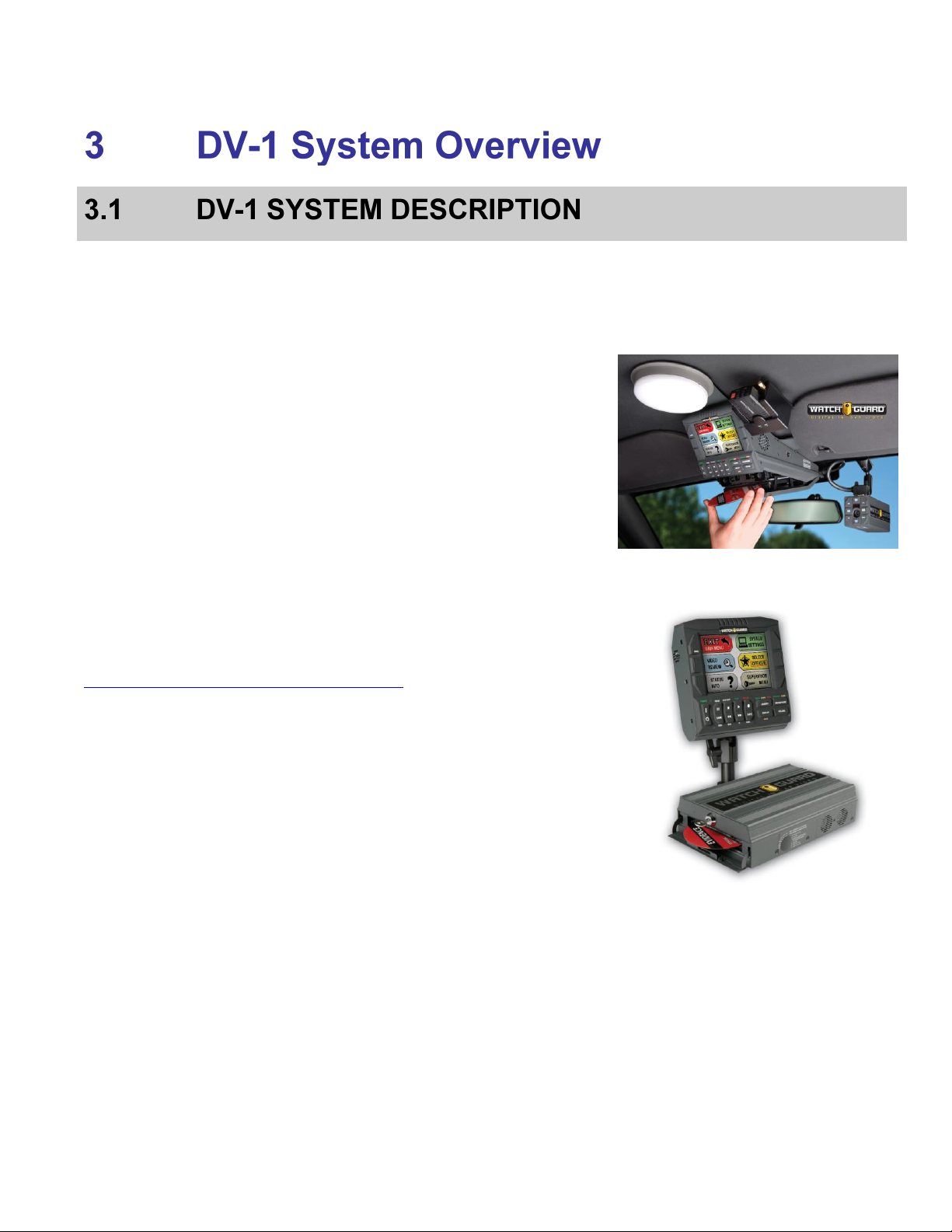
The WatchGuard DV-1 is a digital in-car video system that records
evidence video onto rewritable DVDs that play on regular DVD players. The
system can record up to eight hours of high-quality digital video onto a
single, inexpensive DVD that can be reused many times.
Because of the DVD+RW format that is used in the DV-1, there is no need
for disc finalization before playing back on a computer or DVD player. The
DVDs that come out of the DV-1 are ready to play on your DVD player or
computer. Evidence recorded in the car is the exact evidence that is taken
to court.
The DV-1 is available in either a one-piece overhead system or a two-piece
modular system. The operation of both versions is identical.
The DV-1 includes an integrated, wide temperature range hard drive and a
DVD drive. The system continuously records to the hard drive
whenever the system is on, and only triggered events or manual
recordings are burned to the DVD. The events (traffic stops) are
automatically divided into selectable titles with thumbnail images and
date/time stamps that are organized on a DVD Startup Menu.
For an overview of DV-1 operation, see the DV-1 Training Video at
http://watchguardvideo.com/dv1/dv1-training-videos.
DV-1 features include:
Pre-/Post-Event Recording – Up to 10 minutes of both pre- & post-
event video is automatically added to the beginning and/or end of each
recorded event.
Automatic DVD Back-Up – Up to the last 6 DVDs created are
automatically backed up on the hard drive. Should a DVD be lost,
damaged, or intentionally destroyed, a Supervisor can replicate an
identical copy of the entire missing DVD.
Automatic Disc Overflow Handling – Never runs out of disc space.
While recording, if a DVD fills to capacity, the system automatically
stores overflow video on the integrated hard drive until a new DVD is
inserted.
Background Recording – The DV-1 constantly buffers video to the
integrated hard drive in a large circular loop up to 48 hours long. Hard
drive video can be reviewed in the vehicle and can also be transferred
to a laptop computer using the Fleet Manager Utility software.
Simultaneous Record and Playback – The DV-1 can playback
previously recorded events while simultaneously recording new events.
Figure 1 Overhead Unit
Figure 2 Modular Unit
15
Page 16
ACCESSORIES AND INPUT DEVICES DV-1 SYSTEM OVERVIEW
Fully Redundant Dual Drive Architecture – Includes both an
integrated automotive hard drive and a DVD drive. The system records
events such as traffic stops and drug seizures directly onto DVD-Video
discs while using the hard drive for buffering pre-event video and
automatically backing up the DVDs.
Automatic Event Segmentation – The events (traffic stops) are
automatically divided into selectable titles with thumbnail images and
time/date stamps that are organized on a DVD Startup Menu.
Split-Screen Recording – The DV-1 can record video from any two
cameras simultaneously on one screen. Choose from the Front, Cabin,
or Rear/Auxiliary (optional) cameras to display and record on-screen
together. In addition, switch between cameras on-the-fly while
recording.
The following devices come with the DV-1:
Forward-facing and cabin cameras, either a combination camera
(includes two high-resolution color cameras) or separate cameras:
o Combination camera – includes a forward-facing zoom
camera and a rear-facing cabin camera
o Separate cameras – include a wide dynamic range (WDR)
forward-facing zoom camera and an infrared cabin camera
Optional rear camera
2.4 GHz digital wireless microphone
Amplified cabin microphone
Optional intelligent uninterruptible power supply (battery backup)
The latest accessories and input devices are on the web at:
http://watchguardvideo.com/.
Fleet Manager Utility – A Windows 7/Vista/XP software application used
to create configuration files for loading batch settings into the DV-1 unit.
See Fleet Manager Utility on page 97 for details.
DVD Manager Utility – A Windows 7/Vista/XP software application with
DVD tools including disc copy, save to MPEG-2, and corrupted disc data
recovery. See Software Programs for Playback on page 66 for details.
16
Page 17

DV-1 SYSTEM OVERVIEW PERMISSION LEVELS
The DV-1 is configured with three permission levels. This enables
departments to control who can use the features, change the
configurations, or perform maintenance on the unit.
User – Officer-level permission to use the DV-1 in accordance with the
configuration established by the Supervisor
Supervisor:
o Add or delete users
o Determine operational parameters of the DV-1 (e.g.,
start/stop triggers, default user settings, etc.)
o Set Department Name
o Configure pre-/post-event times
o Choose video quality
o Determine which on-screen text is recorded to the DVD
o Configure input devices
o Update firmware
o Format the hard drive
Administrator – Add or delete Supervisors and their passwords
17
Page 18
CONNECTIONS AND CABLE DIAGRAMS DV-1 SYSTEM OVERVIEW
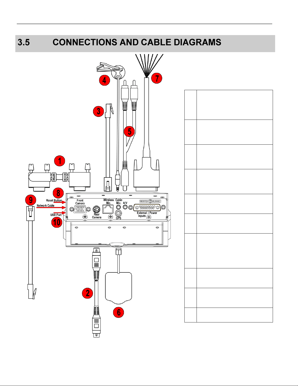
Figure 3 Connections and Cable Diagram – Overhead Unit
Table 1 Overhead Unit Cable
Descriptions
1
Front Camera Cable: Connects
the
DV-1 to the Front/Combination
Camera.
2
Rear/Auxiliary Camera Cable
(optional): Connects the DV-1 to
the Rear/Auxiliary Camera.
3
Wireless Microphone Cable:
Connects the DV-1 to the wireless
microphone system.
4
Cabin Microphone Cable:
Captures audio from inside the
vehicle.
5
A/V: Connects audio/video
components to the DV-1.
6
GPS Antenna: Connects the DV-1
to an optional GPS unit.
7
External Inputs/Power Cable:
Provides power from the vehicle
battery to the DV-1 and provides
external trigger inputs such as
radar, siren, lights, etc.
8
Reset Button: Re-powers the
DV-1.
9
Network Cable: Connects the
DV-1 to a network.
10
USB Port: For future expansion.
18
Page 19
DV-1 SYSTEM OVERVIEW CONNECTIONS AND CABLE DIAGRAMS
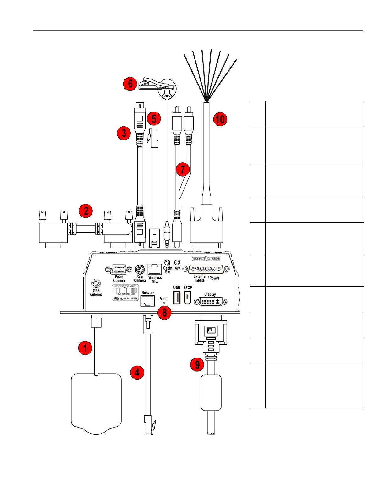
Figure 4 Connections and Cable Diagram – Modular Unit
Table 2 Modular Unit Cable
Descriptions
1
GPS Antenna: Connects the DV-1
to an optional GPS unit.
2
Front Camera Cable: Connects
the
DV-1 to the Front/Combination
Camera.
3
Rear/Auxiliary Camera Cable
(optional): Connects the DV-1 to
the Rear/Auxiliary Camera.
4
Network Cable: Connects the DV1 to a network.
5
Wireless Microphone Cable:
Connects the DV-1 to the wireless
microphone system.
6
Cabin Microphone Cable:
Captures audio from inside the
vehicle.
7
A/V: Connects audio/video
components to the DV-1.
8
Reset Button: Re-powers the
DV-1.
9
Display Cable: Connects the DV-1
to an external display.
10
External Inputs/Power Cable:
Provides power from the vehicle
battery to the DV-1 and provides
external trigger inputs such as
radar, siren, lights, etc.
19
Page 20
FRONT PANEL CONTROLS DV-1 SYSTEM OVERVIEW
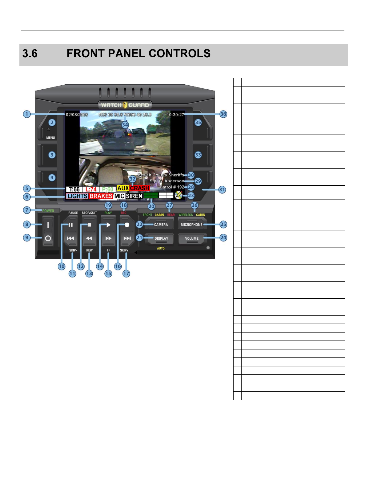
Figure 5 Front Panel Controls
Table 3 Front Panel Controls
1
Date 2 Menu key (Navigation Key 1)
3
Navigation Key 2
4
Navigation Key 3
5
Radar Speeds
Target -- Fastest/Locked – Patrol
6
External Input Indicators
7
Power Indicator
8
On Switch
9
Off Switch
10
Pause
11
Skip backward to previous chapter
12
Stop playback; stop recording; eject DVD
13
Rewind 60, 90, 120, or 180 seconds
depending on the video quality
14
Play
15
Fast-forward 60, 90, 120, or 180 seconds
depending on the video quality
16
Record
17
Skip forward to next chapter
18
Recording Indicator
19
Play Indicator
20
DVD Disc Usage Meter
21
Display Menu
22
Camera Menu
23
DVD Status Icon
24
Volume Menu
25
Microphone Menu
26
Microphone Indicators
27
Camera Indicators
28
Vehicle ID Number
29
Officer Name
30
Department Name
31
Navigation Key 6
32
Crash Detection
33
Navigation Key 5
34
GPS Coordinates (optional)
35
Navigation Key 4
36
Time (Military Format – 24 hours)
20
Page 21
DV-1 SYSTEM OVERVIEW FRONT CAMERA KEYPAD
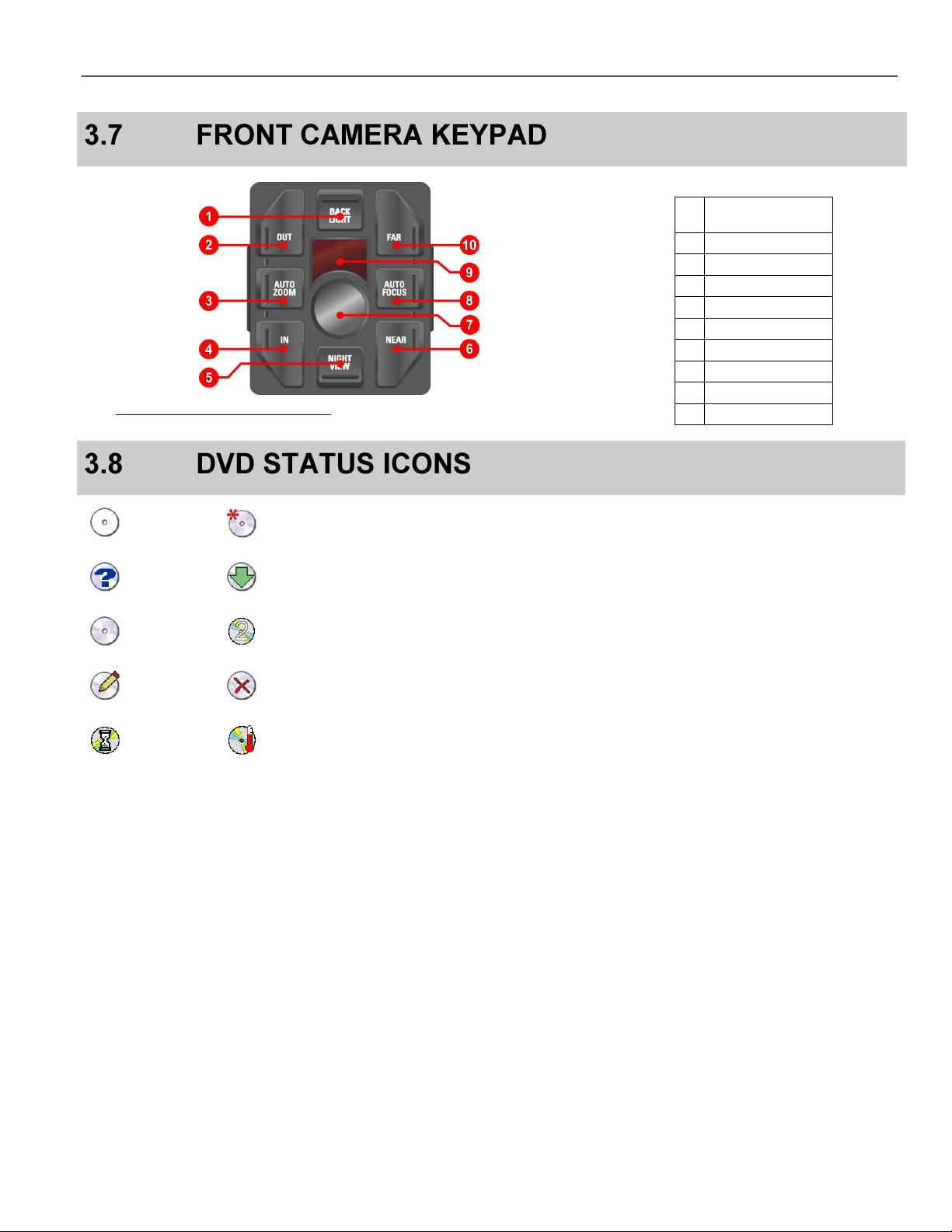
See Front Camera Keypad Controls on page 62 for further details.
Table 4 Front Camera Keypad
1
Backlight
Compensation
2
Zoom Out (Manual)
3
Auto-Zoom
4
Zoom In (Manual)
5
Nightview Mode
6
Focus Near (Manual)
7
Cabin Camera
8
Auto-Focus
9
Infrared Array
10
Focus Far (Manual)
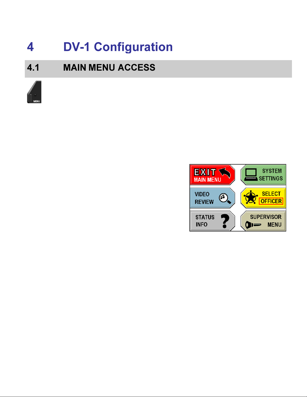
No Disc
Formatting
Detecting
Ejecting
Valid Disc
Overflow Discs*
Writing
Invalid Disc
Busy/Waiting
Out of Temperature Range
*
The overflow numeral displays on top of the currently displayed icon.
21
Page 22

DVD STATUS ICONS DV-1 SYSTEM OVERVIEW
This page intentionally left blank.
22
Page 23
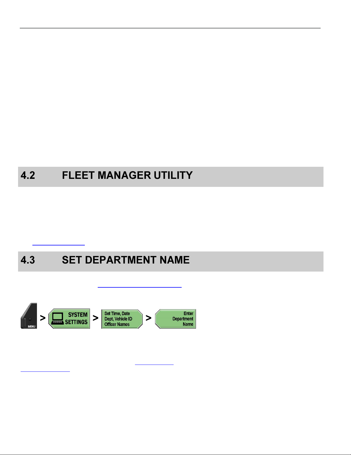
Press the MENU key on the Front Panel of the DV-1.
The Main Menu is displayed with the following options:
Exit Main Menu – Exit the Main Menu and return to the main
camera display screen
Video Review:
o Play back recorded or buffered events on the hard
drive
o Edit event tags, if defined, on recorded events
o Play back video starting with current time
o Define a new event start/stop using the Record
After the Fact (RATF) feature
Status Info – Information about the DVD, hard drive, system,
user, and devices
System Settings:
o Set time/date, department name, vehicle ID, and
officer names
o Setup input devices (radar, siren, etc.)
o Set recording criteria (pre-/post-event, start/stop
triggers, video quality, and camera auto-zoom)
o Manage on-screen text
o Save or restore officer preferences
Select Officer – Select the current officer
23
Page 24
FLEET MANAGER UTILITY DV-1 CONFIGURATION
Supervisor Menu:
o Set system behavior (controls when the system
powers on or off based on vehicle on or off status)
o Set microphone behavior (determines when the
microphone(s) are turned on or off)
o Manage permissions for settings (defines system
permissions for the selected officer)
o Manage DVD and hard drive (format DVD, hard drive
maintenance, reset recording state, set number of
DVDs to backup, burn DVD from backup)
o Manage Supervisor passwords ( requires
Administrator login to add, edit, or delete Supervisor
PIN numbers)
Press the MENU key again on the Front Panel of the DV-1 to exit
the Main Menu and return to the main camera display screen.
Many of the configuration settings in this section can be done easily
using WatchGuard’s Fleet Manager Utility. The Fleet Manager Utility
is a Windows 7/Vista/XP application that is used to create
configuration files that can be burned to a CD and loaded into the
DV-1. Saving multiple configuration files on a single CD simplifies the
process of loading different configurations onto different vehicles.
See Fleet Manager Utility on page 97 for further details.
Supervisor access is required unless the Enter Department Name
permission is set to YES. See Manage Permissions for Settings on
page 80 for details on setting officer permissions.
Press MENU > SYSTEM SETTINGS > Set Time, Date, Dept,
Vehicle ID, Officer Names > Enter Department Name.
If prompted to login, follow the steps listed in Supervisor and
Administrator Login on page 78.
24
Page 25
DV-1 CONFIGURATION SET VEHICLE ID
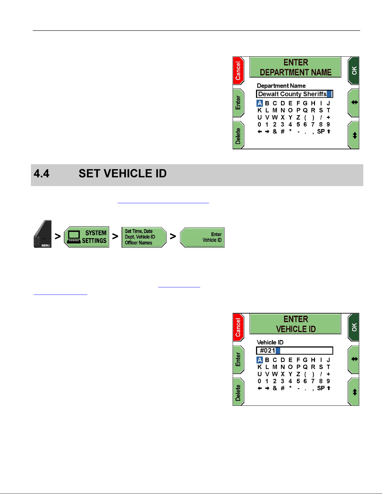
The ENTER DEPARTMENT NAME screen is displayed.
Press the and keys to navigate to the character(s) desired,
and then press Enter to select. To erase an undesired character,
press Delete.
Special characters are as follows:
SP – Space bar
– Uppercase/lowercase letters toggle
and arrows – Move the cursor left and right to allow
character insertion
Press OK to confirm, or Cancel to exit without making changes.
Supervisor access is required unless the Enter Vehicle ID
permission is set to YES. See Manage Permissions for Settings on
page 80 for details on setting officer permissions.
Press MENU > SYSTEM SETTINGS > Set Time, Date, Dept,
Vehicle ID, Officer Names > Enter Vehicle ID.
If prompted to login, follow the steps listed in Supervisor and
Administrator Login on page 78.
The ENTER VEHICLE ID screen is displayed.
Press the and keys to navigate to the character(s) desired,
and then press Enter to select. To erase an undesired character,
press Delete.
Special characters are as follows:
SP – Space bar
– Uppercase/lowercase letters toggle
and arrows – Move the cursor left and right to allow
character insertion
Press OK to confirm, or Cancel to exit without making changes.
25
Page 26
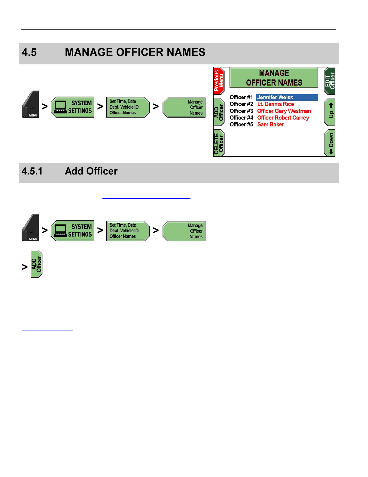
MANAGE OFFICER NAMES DV-1 CONFIGURATION
The Manage Officer Names screens allow you to add, edit, and
delete officers.
Press MENU > SYSTEM SETTINGS > Set Time, Date, Dept,
Vehicle ID, Officer Names > Manage Officer Names.
The MANAGE OFFICER NAMES screen is displayed.
Supervisor access is required unless the Add/Edit Officer Names
permission is set to YES. See Manage Permissions for Settings on
page 80 for details on setting officer permissions.
Press MENU > SYSTEM SETTINGS > Set Time, Date, Dept,
Vehicle ID, Officer Names > Manage Officer Names >
ADD Officer.
If prompted to login, follow the steps listed in Supervisor and
Administrator Login on page 78.
26
Page 27
DV-1 CONFIGURATION MANAGE OFFICER NAMES
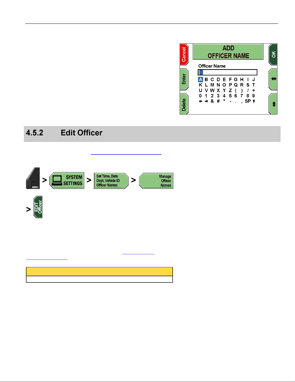
The ADD OFFICER NAME screen is displayed.
Press the and keys to navigate to the character(s) desired,
and then press Enter to select. To erase an undesired character,
press Delete.
Special characters are as follows:
SP – Space bar
– Uppercase/lowercase letters toggle
and arrows – Move the cursor left and right to allow
character insertion
Press OK to confirm, or Cancel to exit without making changes.
Supervisor access is required unless the Add/Edit Officer Names
permission is set to YES. See Manage Permissions for Settings on
page 80 for details on setting officer permissions.
Press MENU > SYSTEM SETTINGS > Set Time, Date, Dept,
Vehicle ID, Officer Names > Manage Officer Names >
EDIT Officer.
If prompted to login, follow the steps listed in Supervisor and
Administrator Login on page 78.
NOTICE
Supervisor access is required to edit a supervisor name.
27
Page 28
MANAGE OFFICER NAMES DV-1 CONFIGURATION
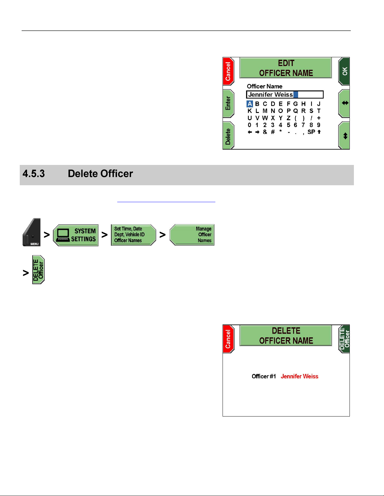
The EDIT OFFICER NAME screen is displayed.
Press the and keys to navigate to the character(s) desired,
and then press Enter to select. To erase an undesired character,
press Delete.
Special characters are as follows:
SP – Space bar
– Uppercase/lowercase letters toggle
and arrows – Move the cursor left and right to allow
character insertion
Press OK to confirm, or Cancel to exit without making changes.
Officer names can only be deleted after a Supervisor PIN has been
entered. Follow the steps listed in Supervisor and Administrator Login
on page 78.
Press MENU > SYSTEM SETTINGS > Set Time, Date, Dept,
Vehicle ID, Officer Names > Manage Officer Names >
DELETE Officer.
The DELETE OFFICER NAME confirmation screen is displayed.
Press DELETE Officer to confirm the deletion and exit the screen,
or press Cancel to exit without making changes.
28
Page 29
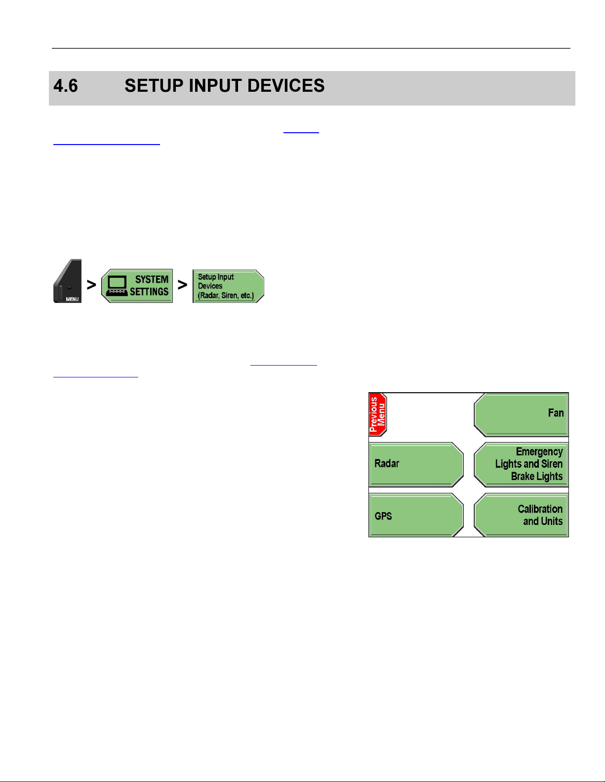
DV-1 CONFIGURATION SETUP INPUT DEVICES
Supervisor access is required to configure input devices unless the
Setup Input Devices permission is set to YES. See Manage
Permissions for Settings on page 80 for details on setting officer
permissions.
The following input devices can be configured:
Radar
Fan
Lights, sirens, and brakes
GPS system
Press MENU > SYSTEM SETTINGS > Setup Input Devices
(Radar, Siren, etc.).
If prompted to login, follow the steps listed in Supervisor and
Administrator Login on page 78.
The SETUP INPUT DEVICES screen is displayed.
29
Page 30
SETUP INPUT DEVICES DV-1 CONFIGURATION
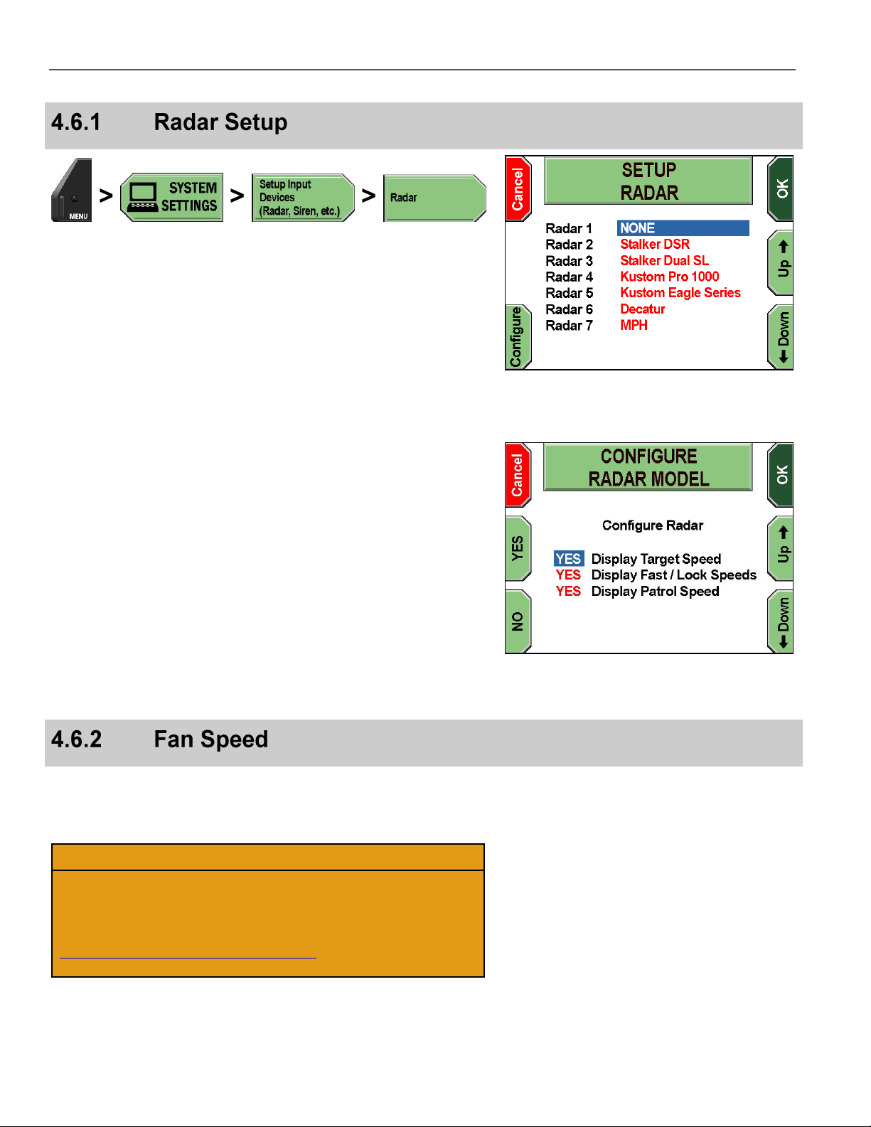
Press MENU > SYSTEM SETTINGS > Setup Input Devices
(Radar, Siren, etc.) > Radar.
The SETUP RADAR screen is displayed.
Press the Up & Down keys to select the radar system, and then
press Configure.
The CONFIGURE RADAR MODEL screen is displayed.
Press the Up & Down keys to select the display setting, and
then press YES or NO for each setting you wish to change.
YES displays the speed on-screen and in the closed-captioning on
the DVD. NO hides the speed from being shown on-screen and in
the closed-captioning.
On-screen terms are as follows:
Display Target Speed – Displays speed of target vehicle
Display Fast/Lock Speeds – Fast displays the fastest vehicle in
a group of cars; Lock displays the locked vehicle speed of the
radar.
Display Patrol Speed – Displays speed of patrol vehicle
Press OK to confirm, or Cancel to exit without making changes.
Increasing the fan speed provides additional cooling for the unit.
Decreasing the fan speed reduces cooling for the unit and may also
reduce the fan noise.
CAUTION!
This operation should only be performed when instructed by
Customer Service personnel.
U.S. customers, call 1-800-605-6734 or email
customerservice@watchguardvideo.com prior to selecting this
option. International customers, contact your local distributor.
30
Page 31

DV-1 CONFIGURATION SETUP INPUT DEVICES
Press MENU > SYSTEM SETTINGS > Setup Input Devices
(Radar, Siren, etc.) > Fan.
The FAN SPEED screen is displayed.
Press the Up & Down keys to adjust the fan speed.
Press Exit when done.
These settings globally enable or disable the sensor inputs for lights,
siren, brake lights, auxiliary input, and crash detection.
CAUTION!
Proceed carefully when changing these settings. If the Emergency
Lights sensor input is set to NO, the DV-1 acts as if it is
disconnected and won’t respond to the emergency light sensor
input. Each of the sensor inputs reacts the same way.
Press MENU > SYSTEM SETTINGS > Setup Input Devices
(Radar, Siren, etc.) > Emergency Lights and Siren Brake
Lights.
31
Page 32

SETUP INPUT DEVICES DV-1 CONFIGURATION
The SETUP BRAKES, LIGHTS, AND SIREN screen is displayed.
Press the Up & Down keys to select the input setting.
Press YES or NO for each setting you wish to change.
YES sets the input to be monitored. NO sets the input to NOT be
monitored.
Press OK to confirm, or Cancel to exit without making changes.
If your system has been equipped with the optional GPS receiver,
there will be a GPS antenna connector on the back of the system,
and you will have the ability to set the GPS to begin monitoring the
receiver. A GPS antenna is shown on the right.
In order for the GPS system to track satellites and provide data to the
DV-1, the GPS antenna needs to be installed where it has a clear
view of the sky.
Press MENU > SYSTEM SETTINGS > Setup Input Devices
(Radar, Siren, etc.) > GPS.
The SETUP GPS screen is displayed.
Press the Up & Down keys to select the INTERNAL NMEA
3.0 GPS or whichever model is installed. Press the Configure key.
32
Page 33

DV-1 CONFIGURATION SETUP INPUT DEVICES
The CONFIGURE GPS screen is displayed.
Press the YES or NO keys to choose whether you want GPS speed
displayed on-screen.
Press OK to confirm, or Cancel to exit without making changes.
CAUTION!
The temperature sensor was calibrated at the factory during
manufacturing. Temperature sensor calibration may be
necessary; however, it should only be performed when
instructed by Customer Service personnel.
U.S. customers, call 1-800-605-6734 or email
customerservice@watchguardvideo.com prior to selecting this
option. International customers, contact your local distributor.
The objective of the calibration process is to match a temperature for
the sensor when the system’s internal temperature would be the
same as a known external temperature. This calibration is best
performed when the system is cool (i.e., no sun exposure). Some
DV-1 units calibrate automatically, and therefore, this option is not
available on those systems.
Press MENU > SYSTEM SETTINGS > Setup Input Devices
(Radar, Siren, etc.) > Calibration and Units.
33
Page 34

RECORDING SETUP DV-1 CONFIGURATION
The CALIBRATION screen is displayed.
Press Next to move the cursor to the next setting. Press the Up &
Down keys to change the selected setting:
Calibration Temperature (DV-1A only) – Typically set to about
12°C (22°F) above the ambient temperature
Temperature Units – Either F (Fahrenheit) or C (Celsius)
Vehicle Speed Units – Either Miles Per Hour (MPH) or
Kilometers Per Hour (KPH)
Crash Sensitivity – Either Low, Medium, or High
NOTICE
The Crash Sensitivity setting may not be displayed on some
systems.
Press OK to save the current calibration, or Cancel to exit without
making changes.
Supervisor access is required unless the Set Pre/Post Event Times
permission is set to YES. See Manage Permissions for Settings on
page 80 for details on setting officer permissions.
The DV-1 features Pre- and Post-Event recording capabilities, which
cause the system to automatically add up to ten minutes of video
footage before and/or after a recorded event.
NOTICE
No audio is recorded during the Pre-Event period unless the
microphones were previously turned on.
Press MENU > SYSTEM SETTINGS > Setup Recording
Criteria > Set PRE/POST Event Recording.
If prompted to login, follow the steps listed in Supervisor and
Administrator Login on page 78.
34
Page 35

DV-1 CONFIGURATION RECORDING SETUP
The SET PRE/POST EVENT RECORDING screen is displayed. The
red outline highlights which soft function is active.
The PRE-Event Time Added to DVD Prior to Record key is
highlighted by default.
Press the Up & Down keys to select the amount of Pre-Event
time to be added to the DVD.
Press OK to confirm, or Cancel to exit without making changes.
Press MENU > SYSTEM SETTINGS > Setup Recording
Criteria > Set PRE/POST Event Recording.
If prompted to login, follow the steps listed in Supervisor and
Administrator Login on page 78.
The SET PRE/POST EVENT RECORDING screen is displayed. The
red outline highlights which soft function is active.
Press the POST-Event Time Added to DVD After
Recording key.
Press the Up & Down keys to select the amount of Post-Event
time to be added to the DVD.
Press OK to confirm, or Cancel to exit without making changes.
35
Page 36

RECORDING SETUP DV-1 CONFIGURATION
Supervisor access is required unless the Manage Start/Stop
Triggers permission is set to YES. See Manage Permissions for
Settings on page 80 for details on setting officer permissions.
The DV-1 features Auto-Record Trigger capabilities, which allow
recording to start based on certain start and stop triggers.
NOTICE
In order for recording to start based on a specific trigger, the input
for that trigger must be monitored. See Lights, Siren, and Brake
Lights on page 31 for further details.
Press MENU > SYSTEM SETTINGS > Setup Recording
Criteria > Set Auto-Record Start and Stop Triggers.
If prompted to login, follow the steps listed in Supervisor and
Administrator Login on page 78.
The SETUP AUTO-RECORD TRIGGERS screen is displayed.
Press Setup START Triggers.
36
Page 37

DV-1 CONFIGURATION RECORDING SETUP
The SET AUTO-RECORD START TRIGGERS screen is displayed.
Press the Up & Down keys to select the start trigger setting.
Press the Change Value key to toggle between YES and NO for
the selected auto-record start trigger. Selecting YES instructs the
DV-1 to begin recording automatically when that trigger is activated.
Selecting NO means that automatic recording will not occur.
Press OK to confirm, or Cancel to exit without making changes.
NOTICE
The Patrol Speed trigger is only displayed if the GPS feature has
been configured to have a value other than NONE. See GPS Setup
on page 32 for information on setting up the GPS values.
4.7.2.1.1 Setup Patrol Speed Trigger
The Patrol Speed trigger needs a speed threshold to indicate when
the trigger should occur. When the Patrol Speed trigger is toggled to
YES, the Change Speed key is displayed on the bottom left.
Press Change Speed.
The SET PATROL SPEED THRESHOLD screen is displayed.
The Patrol Speed threshold can be set to any value from 1 to 150
MPH (1 to 240 KPH).
Press the Up 10 and Down 10 keys to adjust the speed
threshold by increments of +/- 10. Press the Up and Down keys
to adjust the speed threshold by increments of +/-1.
Press OK to confirm, or Cancel to exit without making changes.
37
Page 38

RECORDING SETUP DV-1 CONFIGURATION
Press MENU > SYSTEM SETTINGS > Setup Recording
Criteria > Set Auto-Record Start and Stop Triggers.
If prompted to login, follow the steps listed in Supervisor and
Administrator Login on page 78.
The SETUP AUTO-RECORD TRIGGERS screen is displayed.
Press Setup STOP Triggers.
The SET AUTO-RECORD STOP TRIGGER screen is displayed.
Press the Up & Down keys to set the amount of time that
transpires between the time ALL auto-trigger devices become
inactive and when the system ends recording. Selecting NEVER
means that the system will not auto-stop recording based on inactive
triggers.
Press the Prompt to Confirm? Key to select whether or not the
system requests confirmation to end recording. Selecting YES
instructs the DV-1 to request permission to end the recording.
Selecting NO disables the prompt and automatically ends the
recording as specified.
Press OK to confirm, or Cancel to exit without making changes.
NOTICE
The Auto-Record Stop Trigger only applies when a recording was
initiated by one of the Start triggers. If a recording was manually
started by pressing the Record key, it will not automatically be
stopped or prompted by these auto-stop settings.
38
Page 39

DV-1 CONFIGURATION RECORDING SETUP
Supervisor access is required unless the Set Video Quality
permission is set to YES. See Manage Permissions for Settings on
page 80 for details on setting officer permissions.
The DV-1 allows you select from multiple video quality levels.
Press MENU > SYSTEM SETTINGS > Setup Recording
Criteria > Set Video Quality Mode.
If prompted to login, follow the steps listed in Supervisor and
Administrator Login on page 78.
The SETUP VIDEO QUALITY MODE screen is displayed.
Press the Up & Down keys to choose the quality mode you wish
to select.
Table 5 Video Quality Mode Guide
Quality
Setting
Typical
Resolution
Maximum
2 Hour
2.0 Hours
720x480
Normal *
4 Hour
3.8 Hours
480x480
Long Play
6 Hour
5.5 Hours
352x480
Extended
8 Hour
7.5 Hours
352x480
*
Indicates recommended setting
Press OK to confirm, or Cancel to exit without making changes.
NOTICE
Actual record times will vary because the data rate is not fixed. The
DV-1 uses sophisticated Variable Bit Rate (VBR) encoding to
maximize overall video quality. VBR causes the system to
compress video more (using a lower data rate) when scenes are
stationary, and compress video less (more data) when scenes are
moving.
Supervisor access is required unless the Set Camera Auto Zoom
permission is set to YES. See Manage Permissions for Settings on
page 80 for details on setting officer permissions.
39
Page 40

RECORDING SETUP DV-1 CONFIGURATION
The Auto-Zoom feature allows the front camera to automatically
zoom in on an object or subject for a set period of time, and then
return to its previous zoom level. This is particularly useful for
automatically zooming in on a vehicle license plate.
Press MENU > SYSTEM SETTINGS > Setup Recording
Criteria > Set Camera Auto-Zoom.
If prompted to login, follow the steps listed in Supervisor and
Administrator Login on page 78.
The SET CAMERA AUTO-ZOOM screen is displayed.
Press the Up & Down keys to select the desired setting.
Press the Next key to select between Magnification Level and
Hold Time.
Press OK to confirm, or Cancel to exit without making changes.
On-screen terms are as follows:
Magnification Level – Front Camera magnification setting, from
1X to 10X
Hold Time – Amount of time the camera will hold the
magnification before zooming back out to wide-angle view, from
1 second to 10 seconds
All on-screen text is sampled and generated once per second. The
status of brakes, lights, siren, etc., generally lag behind the activation
by 1-2 seconds in the on-screen display and in the DVD’s Closed-
Captioning Layer.
Press MENU > SYSTEM SETTINGS > Manage On-screen
TEXT.
If prompted to login, follow the steps listed in Supervisor and
Administrator Login on page 78.
40
Page 41

DV-1 CONFIGURATION RECORDING SETUP
The MANAGE ON-SCREEN TEXT screen is displayed.
The three options are discussed in the sections below.
From the Manage On-Screen Text screen, press Display On-
Screen Text in This Vehicle to toggle between YES & NO.
YES sets the system to show text on the DV-1’s screen. NO sets the
system to not show on-screen text.
NOTICE
Changing the Display On-Screen Text in This Vehicle setting
does not affect what text information is recorded on the DVD in the
Closed-Captioning Layer.
From the Manage On-Screen Text screen, press Display Disc
Usage to toggle between YES & NO. YES sets the system to show
the disc usage meter on the DV-1’s screen. NO sets the system to
not show the disc usage meter.
NOTICE
Changing the Display Disc Usage setting does not affect what
text information is recorded on the DVD in the Closed-Captioning
Layer.
See Disc Usage Meter on page 52 for further details.
41
Page 42

RECORDING SETUP DV-1 CONFIGURATION
Supervisor access is required unless the Set Text Fields to Record
permission is set to YES. See Manage Permissions for Settings on
page 80 for details on setting officer permissions.
All metadata text fields are sampled and generated once per second.
These selections affect the text recorded to the DVD’s Closed-
Captioning Layer as well as what displays on-screen.
From the Manage On-Screen Text screen, press Set Text Fields
to Record.
If prompted to login, follow the steps listed in Supervisor and
Administrator Login on page 78.
The SET TEXT FIELDS TO RECORD screen is displayed.
Press the Up & Down keys to select the text field setting.
Press YES or NO for each setting you wish to change. YES sets the
text field to be recorded. NO sets the text field to NOT be recorded.
Press OK to confirm, or Cancel to exit without making changes.
42
Page 43

DV-1 CONFIGURATION SAVE OR RESTORE OFFICER PREFERENCES
The DV-1 automatically creates a user profile with settings for each
officer using the system. The settings included in this profile are:
Brightness levels
Volume levels
Microphone selection
Camera settings:
o Night view
o Back light compensation
o Auto-Zoom magnification level and hold time
o Camera selection
Screen saver settings
User profiles do not include behavior and permission settings
controlled in the Supervisor Menus. When an officer makes a
permissible change to any of their settings in the menu system, those
changes are saved immediately.
A Department Default profile can be saved which will be the
preferences automatically assigned to new officers as they are added
to the system. It also serves as the universal profile that any user can
return to through the RESTORE OFFICER PREFERENCES
screen.
Press MENU > SYSTEM SETTINGS > Save or Restore
Officer Preferences.
The SAVE OR RESTORE OFFICER PREFERENCES screen is
displayed.
Press SAVE Preferences As Department Defaults.
The current officer’s preferences are saved as the Department
Default preferences.
43
Page 44

SAVE OR RESTORE OFFICER PREFERENCES DV-1 CONFIGURATION
Selecting an item in the list and pressing OK causes the selected
preferences to immediately become the current officer’s preferences.
For example, if officer A is the currently selected officer in the
system, and he chooses to restore preferences from officer B, then
officer A’s preferences immediately become the same as officer B’s
preferences.
Press MENU > SYSTEM SETTINGS > Save or Restore
Officer Preferences.
The SAVE OR RESTORE OFFICER PREFERENCES screen is
displayed.
Press RESTORE Preferences from a Previous Save.
The RESTORE OFFICER PREFERENCES screen is displayed.
Press the Up & Down keys to select the preferences to restore.
Press Page & Page to scroll to the next 10 officer names.
Press OK to confirm, or Cancel to exit without restoring any
preferences.
44
Page 45

The DV-1 only records onto 4X-speed DVD+RW discs. Evidencestyle blank DVDs are available through WatchGuard Video:
Highest-quality Sony® or Maxell® 4X-speed DVD+RW blank
media
Bar code identifiers
Unique serial numbers
Boxed section for hand-written identifiers
Ensure that the correct Officer Name is selected prior to using the
DV-1.
Press MENU > SELECT OFFICER.
NOTICE
The Officer Name can be displayed as on-screen text as well as
recorded to the DVD’s Closed-Captioning Layer. See Manage On-
Screen Text on page 40 for further details.
The SELECT OFFICER NAME screen is displayed.
Press the Up & Down keys to choose the officer’s name. Press
Page Dn & Page Up to scroll to the next 10 officer names.
Press Select to select the officer’s name.
See Manage Officer Names on page 26 for information on adding,
deleting, or editing officer names.
45
Page 46

EJECTING A DVD DETAILED DV-1 OPERATION
CAUTION!
Do not use the Manual Eject Button on the DVD drive to eject
discs because the system may not be done writing to the disc.
Use only the STOP/QUIT key. Manually ejecting a DVD when
the system has not finished burning files onto the disc may result
in an unplayable DVD.
Before ejecting a DVD, the officer may use one of the following
methods to ensure that the system has burned all pending files to
the DVD:
The DVD Disc Information screen (see page 126)
The DVD Status Icons (see page 21)
If all recorded events show completed on the DVD Disc Information
screen (e.g., Completed Recordings: 9 of 9) or the status icon
shows a valid disc , and then the DVD can be ejected safely.
To eject a DVD, ensure that the drive door is unlocked, and then
press and hold the STOP/QUIT key for at least 2 seconds.
The CONFIRM EJECT screen is displayed.
Press YES to eject the DVD, or press NO to exit and return to the
main screen.
The message, The DVD will be ejected when all pending
video has been recorded briefly displays on the screen.
Open the DVD drive door and wait for the system to automatically
eject the DVD.
If the drive door is locked, Open drive door flashes across the
screen. Using the key provided with the system, unlock and open the
DVD drive door, and the system will eject the DVD automatically.
Holding the DVD from each side, remove it from the DVD drive slot
and place in a protective sleeve or case. Insert a new DVD into the
drive, close the DVD drive door, and lock it with the key.
46
Page 47

DETAILED DV-1 OPERATION VIDEO REVIEW MODE
To playback recorded or buffered events on the hard drive, first enter
Video Review mode from the Main Menu.
Press MENU > VIDEO REVIEW.
The REVIEW VIDEO FROM HARD DRIVE screen is displayed.
The three options are discussed in the sections below.
NOTICE
The DV-1 can playback events while simultaneously recording new
events (both active or intentional recording plus background
recording). However, the DVD drive will pause any burning activity
while in Video Review mode.
From the video review screen, press Review the Most Recent
Video on the Hard Drive.
Use the Video Control Keys as described on page 48 to review the
video on the hard drive.
Press Hide Menu during playback to hide all graphical items and
text, providing a better view of the recorded event. If menu and text
have been hidden, press Show to display again.
47
Page 48

VIDEO REVIEW MODE DETAILED DV-1 OPERATION
Access Video Review mode as described in Section 5.4.1, and use
the video control keys on the Front Panel to select and playback
recorded events stored on the hard drive.
Pause
Stop playback; stop recording; eject DVD
Play
Record
Skip backward to the start of the previous chapter *
Rewind 60, 90, 120, or 180 seconds depending on the
video quality
Fast-forward 60, 90, 120, or 180 seconds depending on
the video quality
Skip forward to the start of the next chapter
*
The Skip backward button must be pressed within five seconds of the start of the
current chapter. If not, the review location only skips back to the start of the current
chapter.
See Automatic Event Segmentation on page 51 for a description of
how titles and chapters are segmented on a DVD.
Pause Stop Play Record
Previous
Chapter
Rewind Fast
Forward
Next
Chapter
From the video review screen, press View the List of
Previously Recorded Events to display a list of recorded
events.
The SELECT RECORDED EVENT screen is displayed.
Press the and keys to highlight the recorded event to review.
Press Page Dn & Page Up to scroll to the next 10 recorded
events. Red items are editable and black items are not.
Press Select to review the recorded event’s details and/or playback
the recorded event.
Press Cancel to return to the video review screen.
48
Page 49

DETAILED DV-1 OPERATION VIDEO REVIEW MODE
The RECORDED EVENT DETAIL screen displays, showing details
about the highlighted recorded event.
Press Page Dn to display additional details about the recorded
event. Press Play to view the recorded event. Press Reburn to
reburn this recorded event as a new event on the current DVD.
Press Edit Tags to edit the event tags for the recorded event
displayed. This key is only available for recorded events that have
event tags associated.
This option allows the officer to specify a start and stop time to
define a new event. All available video between the two times
becomes the next event on the DVD.
From the video review screen, press Define a New Event
Start/Stop (Record After the Fact).
The DEFINE NEW EVENT screen displays.
Press Next and Prev to highlight the desired field to change.
Press the Up and Down keys to change the value.
Press OK to define the new event.
NOTICE
The video selected for the event follows the Video Review Access
Levels as defined on page 82.
The CREATE NEW EVENT screen displays.
Press CREATE to create the new event.
If event tags are configured, the officer is then prompted for each
event tag. See Event Tags on page 97 for further details.
49
Page 50

RECORDING TO DVD DETAILED DV-1 OPERATION
If the unit is on, it is automatically buffering video to the hard drive.
When you press the RECORD key, it then begins recording to the
DVD from that point in time forward. If a Pre-Event Time is set up, it
will first burn that buffered amount of time onto the DVD and then
catch up to near real-time. When the STOP/QUIT key is pressed,
this ends an event (title) on the DVD.
The DV-1 can be set to record using various methods. The available
methods for beginning or ending a DVD title are:
Start Triggers (see Setup START Triggers on page 36):
o Record key
o Emergency lights activation
o Emergency siren activation
o Wireless microphone activation
o Auxiliary trigger activation
o Crash detection
Stop Triggers (see Setup STOP Triggers on page 38)
o STOP/QUIT key
o Auto STOP trigger (timed)
NOTICE
If DVD capacity is reached while recording, the title is ended, but
recording does not stop. The DVD is ejected, and the recording will
continue onto the next DVD.
See Automatic Disc Overflow Recording on page 54 for further
details.
When actively recording, the Front Panel RECORD LED glows red,
and the red LED by the camera lens is activated.
50
Page 51

DETAILED DV-1 OPERATION RECORDING TO DVD
Press the STOP/QUIT key to stop recording to DVD. Each
recorded event creates a title on the DVD.
NOTICE
If the DV-1 has been configured to use event tags, the officer will
be prompted to provide additional event details when ending a
recording (pressing the STOP/QUIT key). See Event Tags on
page 97 for further details.
The Front Panel RECORD LED is extinguished indicating that the
DV-1 is no longer actively recording, and a message similar to the
one at the right displays for 5 seconds. If event tags are configured,
the first event tag prompt will be displayed instead of this message.
Note: The Recording # at the top is the number of the recording on
the DVD. When a new DVD is inserted, the numbering restarts at 1.
Each recording, no matter the length, is represented by a single
navigable title on the DVD (represented by a thumbnail as shown on
the right). A title is further subdivided into up to 30-minute chapters.
For example, on a 75-minute recording, there is only 1 thumbnail on
the DVD title menu. However, the title will contain 3 chapters: 30
minutes, 30 minutes, and 15 minutes in length.
When playing the title, the user may skip to the next chapter, which
skips ahead 30 minutes into the title.
When a record trigger is activated, the system begins a new title.
When a stop trigger is activated, the system completes the title.
NOTICE
If the system has been set to capture Pre-/Post-Event video, this
video is included as a part of that title.
51
Page 52

RECORDING TO DVD DETAILED DV-1 OPERATION
The system stops burning to the DVD and displays the icon on the
right in the following situations:
Reason DVD Stops Burning
DVD
Status Icon
The DVD drive’s temperature is out of range
There is no DVD in the drive
The media in the drive is not DVD+RW
The DVD is full
The DVD is being formatted
The Disc Usage Meter shows graphically how much video has been
recorded on the current DVD. The bar expands as video is recorded,
with axis lines at 25%, 50%, and 75%.
The top bar shows how much video is scheduled to be burned to the
DVD. The bottom bar shows how much of the scheduled video has
been burned to the DVD. The bar is green until there are only 30
minutes available on the DVD.
Green = > 30 minutes
Yellow = 30 minutes
Red = 10 minutes
When the DVD has only 30 minutes remaining:
An alert sounds and a warning message displays
After the message disappears, the meter bar turns yellow
The next recording is likely to overflow the current DVD causing
part of the recording to be on the current DVD and the rest to be
on the next DVD. Find a good stopping point and put a new disc
in the DVD drive to continue recording onto the next DVD. After
the low disc space warning has been displayed, it is good
practice to insert a new disc prior to beginning another recording
event. Note: Do not eject the first disc until the system has
completed burning any scheduled video.
52
Page 53

DETAILED DV-1 OPERATION RECORDING TO DVD
When the DVD has less than 10 minutes remaining:
An alert sounds and a warning message is displayed
After the message disappears, the meter bar turns red
The disc full condition is imminent. Be prepared to insert a new
DVD.
When the DVD has only 2 minutes remaining:
An alert sounds and a warning message is displayed
The disc usage meter bar remains red
The disc full condition is critical and recording will overflow
momentarily.
NOTICE
No video is lost if a recording overflows the current DVD capacity.
The overflowed video is simply burned onto the next DVD.
53
Page 54

RECORDING TO DVD DETAILED DV-1 OPERATION
If a DVD fills to capacity while recording, the system automatically
stores the overflow video on the hard drive. The overflowed video is
added to the subsequent DVD as one or more new titles.
Example of a Disc Overflow Scenario
With only 30 minutes of space remaining on the current DVD, a
traffic stop is initiated. The stop becomes a DUI arrest which lasts for
1 hour.
The first 30 minutes of the event are burned onto the first DVD.
This fills the disc, and no more video is added to that disc. A
Disc is Full message begins to flash on the screen.
The system continues recording the DUI stop (without missing a
second of video) by queuing the overflow video onto the hard
drive. Do not press the STOP/QUIT key until it is time to stop
recording the DUI event.
The officer may open the drive door (which ejects the DVD) at
any time after the Disc is Full message is displayed. This can
be done after the event has concluded or while the event is still
being recorded.
Insert a new DVD and format it by pressing YES. The 30
minutes of overflow video are added to the 2nd DVD as a new
title.
Disc Overflow Scenario that Spans Multiple DVDs
If a system is placed into record and left unattended for a very long
time, or the system has been operating without a DVD for a long
time, it is possible to overflow the recording beyond the capacity of a
2nd DVD. The system can overflow up to 6 entire DVDs worth of
video. The number of discs that can overflow is the number of DVD
backups that are configured. See Set Number of DVDs to Backup on
page 86 to configure this number.
When overflow video spans more than one DVD, the DVD Status
Icon on the screen displays a number shown on top of the DVD icon
(a number from 1 to 6). This number represents the total number of
DVDs required to catch up.
For example, if the icon shows a DVD with the number 2, this means
that over 2 complete DVD’s worth of video has overflowed, and it is
currently queuing video for a 3rd disc.
The DV-1 always burns the oldest overflow disc first.
54
Page 55

DETAILED DV-1 OPERATION SPLIT-SCREEN DISPLAY
The purpose of Covert Mode is to allow the officer to secretly record
activities without suspects in the vehicle being aware that they are
being recorded.
To enter Covert Mode, press and hold the Power On key for 3 or
more seconds. The following occurs:
An initial beep is heard when the Power On key is pressed
Continue to hold the Power On key until a second, lower tone
beep is heard.
Release the key and Exiting normal operating mode…
displays on the screen
Another set of beeps is heard and the system screen goes black
Sounds and lights are turned off on the system
The system changes to a split-screen view of the front and cabin
cameras
The live (wireless) microphone is muted and the cabin
microphone is turned on
Recording starts
To exit Covert Mode, press the STOP/QUIT key. The recording
continues and the screen remains in split-screen view. Press the
STOP/QUIT key again to stop recording.
NOTICE
Covert Mode differs from Dark Mode (see page 57). Dark Mode
only temporarily turns off the system display and LEDs. It does not
automatically start recording, nor does the system go into splitscreen view, as it does in Covert Mode.
With the split-screen feature, the DV-1 can simultaneously display
and record images from two cameras. When a split screen image is
displayed and recording is triggered, both images are recorded on
the evidence DVD.
The following illustration is an example of a split-screen view using
the Combination Camera. In this example, the top half of the
screen displays the view through the windshield, while the bottom
half displays the cabin view (or the rear camera view, if equipped).
The camera views shown on the display screen are always the same
as what is being recorded. The Front Camera is always displayed
on the top of the split-screen.
See Camera Key on page 61 to select the views to display and
record.
55
Page 56

CLOSED-CAPTIONING TEXT ON DVD PLAYBACK DETAILED DV-1 OPERATION
All of the DV-1’s textual information (metadata) is saved on the DVD
in a format called the Closed-Captioning Layer. The advantages of
using the Closed-Captioning Layer for displaying this information
are:
Text display is crisp and readable
Text can be turned on or off during playback so the video image
is not permanently obscured
Each field (black-boxed section) is displayed only when data is
present. For example, if the radar is not connected or active, the box
for radar data is not shown on-screen.
NOTICE
Closed-Captioning is generally handled by the television set (not
the DVD player). Follow your television manufacturer’s instructions
for activating this feature. If your television provides multiple
closed-captioning formats, choose the C1 format. C1 Format
Closed-Captioning is required to display text during playback.
The WatchGuard Windows application called DVD Manager Utility
(DMU) is designed to play or copy evidence DVDs. Closedcaptioning can be toggled on or off in DMU by selecting the option
shown on the right from the Tools menu.
Documentation for all versions of the DMU is on the web at
http://watchguardvideo.com/support
See Software Programs for Playback on page 66 for further details
on the DMU application.
56
Page 57

DETAILED DV-1 OPERATION FRONT PANEL CONTROLS
CAUTION!
Display brightness levels may be adjusted down to off. Once the
display is turned off, the operator can no longer view the menu
system. Press any of the soft keys to return the display to normal.
Press the DISPLAY key on the Front Panel.
The DISPLAY screen is displayed.
Press the Next key to switch between display or panel brightness.
Press the Up & Down keys to set the brightness level for the
selection.
Dark Mode allows the system display and LEDs to be temporarily
switched off.
Press the DISPLAY key on the Front Panel.
The DISPLAY screen is displayed.
Press Dark Mode to temporarily turn off the display and LED
indicators on the Front Panel. Press any key to turn the display and
LEDs back on. The Screen Saver is discussed in the section below.
NOTICE
Dark Mode differs from Covert Mode (see page 55). Dark Mode
only temporarily turns off the system display and LEDs. It does not
automatically start recording, nor does the system go into splitscreen view, as it does in Covert Mode.
57
Page 58

FRONT PANEL CONTROLS DETAILED DV-1 OPERATION
The screen saver functionality can be configured to be disabled,
active all the time (day and night), or active only during night view
mode (night only).
Press the DISPLAY key on the Front Panel.
The DISPLAY screen is displayed.
Press Screen Saver.
The SETUP SCREEN SAVER screen is displayed.
Press the Screen Saver Activation key until DISABLED is
displayed, to configure the screen saver to never activate.
Press the Screen Saver Activation key until ENABLED is
displayed, to configure the screen saver to always activate (day and
night), after the specified time interval.
Press the Up and Down keys to set the desired amount of time
until the screen saver activates.
Press OK to confirm, or Cancel to exit without making changes.
58
Page 59

DETAILED DV-1 OPERATION FRONT PANEL CONTROLS
Press the Screen Saver Activation key until NIGHT VIEW is
displayed, to configure the screen saver to activate only during night
view mode (night only), after the specified time interval.
Press the Up and Down keys to set the desired amount of time
until the screen saver activates at night.
Press OK to confirm, or Cancel to exit without making changes.
NOTICE
Users cannot configure different screen-saver behavior for day and
night modes. The only options are never active, active all the time,
or active only at night.
Press the Define Screen Saver Behavior During Events
key to define how the screen saver behaves when a trigger causes a
recording to start.
The DEFINE BEHAVIOR DURING EVENTS screen is displayed.
Press the Exit Screen Saver On Auto-Record Start
Trigger key to indicate whether the unit automatically exits the
screen saver when a recording is triggered. Selecting YES causes
the screen saver to deactivate when a recording is triggered.
Selecting NO keeps the screen saver active even though a recording
has been triggered.
Press the Screen Saver Allowed During Recording key to
indicate whether an active screen saver is allowed while the unit is
recording. Selecting YES allows the screen saver to activate while
the unit is recording. Selecting NO causes the screen saver to NOT
activate while the unit is recording.
Press OK to confirm, or Cancel to exit without making changes.
59
Page 60

FRONT PANEL CONTROLS DETAILED DV-1 OPERATION
CAUTION!
High volume levels for the LIVE (wireless) setting may result in
feedback between the speakers and the wireless microphone.
Press the VOLUME key on the Front Panel.
The VOLUME screen displays.
Press the Select & Select keys to choose between LIVE
(wireless), Playback Cabin, or Playback Wireless.
Press the Up & Down keys to set the volume level for one or
more of the following selected items:
LIVE (wireless) – Adjusts live feedback from the wireless
microphone. This allows someone in the vehicle to monitor a live
conversation transmitting from the wireless microphone. This
should normally be set to the minimum.
Playback Cabin – Adjusts volume of the cabin microphone
when reviewing recorded video. Does not affect microphone
sensitivity
Playback Wireless – Adjusts volume of the wireless
microphone when reviewing recorded video.
Press Exit when finished.
60
Page 61

DETAILED DV-1 OPERATION FRONT PANEL CONTROLS
The DV-1 can operate up to 3 cameras:
Front Camera – Main windshield-view zoom camera
Cabin Camera – Backseat-view camera
Rear/Auxiliary Camera – Optional and may have zoom
capability
The system automatically senses which cameras are installed and
provides controls in the Camera Menu accessible from the Front
Panel.
The standard Combination camera consists of the Front and Cabin
cameras which are built into the same enclosure. It includes Camera
Keypad controls on the camera back which control only the Front
camera. The Cabin camera has a fixed, wide-angle lens, and it does
not include any manual controls.
The optional Rear/Auxiliary Camera is controlled exclusively
through the Camera Menu on the Front Panel.
Press the CAMERA key on the Front Panel.
The Camera Menu is displayed.
A list of available cameras is displayed on the right side of the
screen. Press the corresponding key to the right of the key label to
turn the desired camera ON or OFF.
Only two cameras can be displayed on-screen at once. The Front
camera is always favored. For example, if the Front camera and
Cabin camera are both ON, and the Rear/Auxiliary camera is
selected, the Cabin camera is turned OFF.
LED indicators above the CAMERA key indicate the currently active
cameras. The LED is green for the Front camera, yellow for the
Cabin camera, and red for the Rear/Auxiliary camera.
Press the FRONT Camera Controls or the REAR Camera
Controls key.
61
Page 62

FRONT CAMERA KEYPAD CONTROLS DETAILED DV-1 OPERATION
The Front Camera or Rear Camera screen is displayed. The Front
Camera screen is shown at the right.
NOTICE
If no camera is connected to the rear camera port on DV-1 startup,
or a third-party camera (e.g., a thermal imaging camera) is
connected to the rear camera port, then there is no REAR
Camera Controls key, and the text on the REAR Camera key
is changed to AUX Camera.
The following Camera Keypad controls are available for the Front
camera:
Backlight – Brightens the overall exposure; compensates for
darkening effect of sunrise, sunset, or bright lights in the
background
Auto-Focus – The camera focuses itself
Nightview – Optimizes the camera settings for nighttime
operation; Auto-Focus is turned off and the focus point is set to
about 50 feet
Auto-Zoom – Zooms to a preset level and holds zoom for a
preset time
Out and In – Manually controls the zoom
Far and Near – Manually adjusts the focus
The Back Light Compensation feature brightens the overall
exposure when the subject in the foreground would otherwise
appear dark due to strong back-lighting. It lightens the overall
exposure to compensate for the darkening effect of sunrise, sunset,
or bright lights in the background.
62
Page 63

DETAILED DV-1 OPERATION FRONT CAMERA KEYPAD CONTROLS
Press the BACK LIGHT key on the Camera Keypad.
A Green LED indicates that the feature is ON (active), and a Blue
LED indicates the feature is OFF (inactive).
Alternatively, select either the Front Camera or the Rear Camera
from the Camera Menu on the Front Panel (see Camera Key on
page 61), and then press the Backlight Comp key to toggle
between ON or OFF.
Activating Night View mode optimizes the camera settings for
nighttime operation.
When Night View mode is turned on, the DV-1 automatically sets
the manual focus to about 50 feet. When Night View mode is turned
off, auto-focus is turned back on.
When set to AUTO, the system automatically turns Night View on
when it gets dark (and manual focus is set to about 50 feet), and
turns it back off when it gets light (and auto-focus returns).
Press the NIGHT VIEW key on the Camera Keypad. It toggles
between ON, OFF, and AUTO. When set to AUTO, the LED turns
off for a couple of seconds, and then it will turn either blue or green
depending on whether it is night or day.
A Green LED indicates that the feature is ON (active), and a Blue
LED indicates the feature is OFF (inactive).
Alternatively, select either the Front Camera or the Rear Camera
from the Camera Menu on the Front Panel (see Camera Key on
page 61), and then press the Night View key to toggle between
ON, OFF, or AUTO.
When set to AUTO, if the system determines that Night View is not
needed, the background of the key turns from green to red.
Night View defaults to AUTO when the DV-1 is rebooted.
63
Page 64

FRONT CAMERA KEYPAD CONTROLS DETAILED DV-1 OPERATION
The Auto-Zoom feature allows the camera to automatically zoom in
on an object or subject for a set period of time, and then return to its
previous zoom level. This is particularly useful for automatically
zooming in on a vehicle license plate.
If the AUTO ZOOM key is pressed while the camera is operating in
Night View mode, the camera will first activate Auto-Focus, wait a
few seconds for the Auto-Focus to settle, and then begin the zoom
sequence. After completing the Auto-Zoom sequence, the fixed
focus position is reset back to around 50 feet.
Press the AUTO ZOOM key on the Camera Keypad to initiate the
zoom sequence.
A Green LED indicates that the feature is ON (active), and a Blue
LED indicates the feature is OFF (inactive).
See Set the Auto-Zoom on page 39 for details on setting the
Magnification Level and Hold Time.
Alternatively, select either the Front Camera or the Rear Camera
from the Camera Menu on the Front Panel (see Camera Key on
page 61), and then press the Auto Zoom key to initiate the zoom
sequence. The on-screen status displays ON during the zoom
period, and then changes back to OFF when done.
Press and hold the IN and OUT keys which are located above and
below the AUTO ZOOM key on the Camera Keypad.
Alternatively, select either the Front Camera or the Rear Camera
from the Camera Menu on the Front Panel (see Camera Key on
page 61), and then press the Zoom key.
Press and hold the In & Out keys to control the zoom level.
64
Page 65

DETAILED DV-1 OPERATION FRONT CAMERA KEYPAD CONTROLS
The bar scale at the bottom of the screen indicates the magnification
level of the current zoom setting. To the left of the vertical bar is the
optical zoom area, and to the right is the digital zoom area. W is wide
angle, and T is telephoto.
The scale indication takes several seconds to receive updated zoom
positions from the camera.
The Front Camera uses a vari-focus lens system that maintains
focus regardless of the magnification level.
Press the AUTO FOCUS key on the keypad to allow the camera to
self-focus.
Alternatively, select either the Front Camera or the Rear Camera
from the Camera Menu on the Front Panel (see Camera Key on
page 61), and then press the Auto Focus key to allow the camera
to self-focus.
Use the Camera Keypad and zoom all the way in to an object at the
desired distance.
Use the Far and Near keys to manually adjust the focus.
Zoom back out to a wide angle view, and the object will remain in
crisp focus.
65
Page 66

PLAYBACK ON COMPUTERS AND DVD PLAYERS DETAILED DV-1 OPERATION
Alternatively, select either the Front Camera or the Rear Camera
from the Camera Menu on the Front Panel (see Camera Key on
page 61), and then press the Focus key.
With the Focus screen still displayed, use the Camera Keypad and
zoom into an object at the desired distance.
From the Front Panel, use the Far and Near keys to manually
adjust the focus.
Zoom back out to a wide angle view, and the object will remain in
crisp focus.
Because of the DVD+RW format that is used in the DV-1, there is no
need for disc finalization before playing back on a computer or DVD
player. The DVDs that come out of the DV-1 are ready to play on
your DVD player or computer. Evidence recorded in the car is the
exact evidence that is brought into court.
WatchGuard’s DVD Manager Utility is the recommended software
program for playback. Documentation for all versions of the DVD
Manager Utility is on the web at:
http://watchguardvideo.com/support
Some of the main advantages are:
The ability to recover video from corrupted media
Single-title copies
Save video titles as MPEG-2 files
NOTICE
Other programs such as Windows Media Player and RealNetworks’
RealPlayer may be utilized as well if the user chooses.
66
Page 67

DETAILED DV-1 OPERATION PLAYBACK ON COMPUTERS AND DVD PLAYERS
Below is the main window of the DMU. To play a DVD, click the Play Video button.
The Video Player screen is displayed. Click the Load DVD link in the center of the screen.
67
Page 68

PLAYBACK ON COMPUTERS AND DVD PLAYERS DETAILED DV-1 OPERATION
The DVD’s main screen is displayed. Click a title to play it.
68
Page 69

There are several different types of microphones that may be
included with the DV-1 system. For specific information on your
particular microphone, please refer to the manufacturer’s manual that
is packaged with your microphone.
Press the MICROPHONE key on the Front Panel.
The MICROPHONES screen is displayed.
Corresponding LED indicators are lit above the MICROPHONE key
on the Front Panel to indicate which microphones are active.
Press Cabin Mic to turn the cabin microphone ON or OFF.
Press Wireless Mic to turn the wireless microphone ON or OFF.
NOTICE
Officer may or may not have permission to turn off some or all
microphones. See Set Microphone Behavior on page 80.
Place the microphone transceiver in the docking base.
After a few seconds a tone indicates that the wireless microphone
has synchronized with the system.
NOTICE
Any microphone transceiver can be synchronized with any
microphone base; however, only one wireless microphone can be
used with one microphone base at a time. To switch to a different
microphone, place the desired transceiver into the docking base to
synchronize it with the system.
69
Page 70

LAPEL MICROPHONE PLACEMENT CABIN AND WIRELESS MICROPHONES
The wireless microphone features an optional lapel microphone with
a foam wind screen. For the best possible sound quality, place the
lapel microphone as described below:
Placement #1: Clip the lapel microphone inverted near the center of
the chest at least 12 inches away from the face. Placing the
microphone too close to the face results in distorted audio and the
microphone is less likely to pick up a suspect’s voice.
Placement #2: Clip the lapel microphone near the center of the belt.
Better sound balance from both the officer and the subject may be
achieved by this placement.
NOTICE
A microphone is built into the belt-pack transceiver. Therefore, a
lapel microphone is not required nor included with the DV-1. When
using a lapel microphone, should the lapel microphone be
disconnected, the built-in microphone takes over.
Since the built-in microphone does not have a wind screen, audio
performance is degraded on windy days.
70
The Status Menus display important system information about the
DV-1. These screens are for informational purposes only and do not
allow for any changes to system settings or functions.
Page 71

View DVD information by pressing MENU > STATUS INFO.
The SYSTEM STATUS INFORMATION – DVD Disc Information
screen is displayed by default. There are up to three available
information screens when you press the middle-left key, DVD Disc
Information, DVD Drive Information, and DVD Media Information
(if a DVD is present).
71
Page 72

DVD DISC, DRIVE, AND MEDIA INFORMATION SYSTEM STATUS INFORMATION SCREENS
For the DVD Disc Information screen, the on-screen terms are:
Video Quality – The quality of video set to record to the DVD
(see Set Video Quality on page 39)
Record Time – The estimated amount of time the DVD can hold
based on the quality setting
Disc Usage – The percentage of disc space that has already
been allocated
Video Recorded – The number of minutes of video already
burned to the DVD
Time Left on Disc – The estimated number of available minutes
remaining on the disc
Un-Burned Video – Buffered video data waiting to be transferred
to the DVD
Recording State – Indicates whether or not the system is
currently in an active recording mode*
DVD State – Displays the current step in the burning process
Completed Recordings – Indicates how many titles have been
recorded to the DVD
*
If the system is set up to record Post-Event video (see Set Post-
Event Time on page 35), the Recording State could show as
Recording even after the STOP/QUIT key is pressed because the
system is still recording for the remaining time of the Post-Event.
For the DVD Drive Information screen, the on-screen terms are:
Vendor ID – The name of the DVD drive manufacturer
Product ID – The model number of the DVD drive
Version – The firmware version of the DVD drive
Vendor Data – Data provided by vendors for their purposes; this
field is not always used
72
Page 73

SYSTEM STATUS INFORMATION SCREENS HARD DRIVE INFORMATION
For the DVD Media Information screen (available only if a DVD is
present), the on-screen terms are:
Media Code – Identifies the manufacturer of the DVD and assists
the DVD burner in using the best write strategy
Media Revision – The revision of the DVD
Disc Size – The physical dimension of the DVD
Book Type – The type of DVD, for example, read only, read/write
Linear Density – The amount of space used for one bit
Track Density – The amount of space used for one track
Number of Layers – The number of layers on the DVD (1 or 2)
View hard drive information by pressing MENU > STATUS INFO >
Hard Drive.
On-screen terms are as follows:
Video Quality – The quality of resolution set to record to the hard
drive
Drive Video – The amount of time in hours recorded on the hard
drive
Oldest Video – The date and time of the oldest video on the hard
drive
Partition Size – The amount in MB of useable space on the hard
drive
Physical Size – The amount in MB of available space on the
hard drive
NOTICE
By default, only 40 GB of the hard drive space is used. To format
the drive to use all the available space, see Format Hard Drive to
Maximum Capacity on page 111.
73
Page 74

SYSTEM INFORMATION SYSTEM STATUS INFORMATION SCREENS
View software and hardware versions by pressing MENU >
STATUS INFO > System.
On-screen terms are as follows:
Date/Time – The date and time currently set
OS – Main system software version
IOP – Software version of the I/O Processor
SysFPGA – System FPGA version
Front Panel – Keypad software version
DVD Decoder – Decoder software version
SplitScreenFPGA – Split-screen FPGA version
Power Board – Power supply hardware version
Main Board – Motherboard hardware version
Actual version information will likely be different than what is shown
on the right.
View user information by pressing MENU > STATUS INFO >
User.
On-screen terms are as follows:
Department – Name of agency
(configured in Set Department Name on page 24)
Officer – Officer name in use
(configured in Manage Officer Names on page 26)
Supervisor – Supervisor login status
(discussed in Supervisor and Administrator Login on page 78)
Vehicle ID – Vehicle ID number
(configured in Set Vehicle ID on page 25)
74
Page 75

SYSTEM STATUS INFORMATION SCREENS DEVICE INFORMATION
View device information by pressing MENU > STATUS INFO >
Devices.
On-screen terms are as follows:
GPS – GPS status (configured in GPS Setup on page 32),
including the latitude and longitude readings from the device if
one is configured for the system
Radar (configured in Radar Setup on page 30)
o T=Target Speed
o P=Patrol Speed
o L=Locked Target Speed
o F=Fastest Vehicle Speed
Accelerometer – Reports the G-force in each of the 3 directions
(X, Y, and Z) at the current time
Brakes* – Brake status (ON = Pedal Depressed)
Lights* – Light bar status
Siren* – Siren status
Temp – System temperature
Drive Door – DVD drive door status
Ignition – Ignition status
*
Configured in Lights, Siren, and Brake Lights on page 31.
75
Page 76

DEVICE INFORMATION SYSTEM STATUS INFORMATION SCREENS
This page intentionally left blank.
76
Page 77

The DV-1 is configured with three permission levels: User,
Supervisor, and Administrator. This enables departments to
control who can use the features, change the configurations, or
perform maintenance on the unit. See Permission Levels on page
17 for further details.
NOTICE
A Supervisor PIN number MUST be established before any
Supervisor settings or controls can be accessed. See Add
Supervisor PIN on page 89 for further details.
When an officer name is initially added to the system, they are
simply a User. The system requests a PIN number when the officer
is changed to a Supervisor.
Supervisor PIN numbers (passwords) can only be added, edited,
and deleted by someone with an Administrator PIN number. There is
only ONE Administrator PIN per agency.
Any Supervisor PIN number can be used to access restricted
screens regardless of the active officer name. There is no need to
change the active officer to the Supervisor name. This allows a
Supervisor to gain quick access to assist a non-Supervisor officer.
Some functions require a Supervisor PIN to access the selection.
Others may require an Administrator PIN. The steps for entering a
PIN number are the same in either case. The SUPERVISOR LOGIN
screen is used in the following example for simplicity purposes.
NOTICE
The Supervisor is automatically logged out when exiting the Main
Menu.
77
Page 78

SUPERVISOR AND ADMINISTRATOR LOGIN SUPERVISOR/ADMINISTRATOR FUNCTIONS
If you have not previously logged in as Supervisor, or if you have
exited the Main Menu after being logged in as Supervisor, the
system asks for a Supervisor PIN number when accessing the
Supervisor Menu.
Press MENU > SUPERVISOR MENU.
Press the and keys to navigate to the correct number, and then
press Enter to select each number. If you enter an incorrect
number, Invalid PIN is displayed and you must start over again.
Press Cancel before the fifth number is entered to exit without
logging in. The Login key is automatically pressed when the fifth
number is selected.
The SUPERVISOR MENU is displayed.
System behavior settings control when the DV-1 system powers on
or off based on vehicle on or off status.
Press MENU > SUPERVISOR MENU > Set System
Behavior.
If prompted to login, follow the steps listed in Supervisor and
Administrator Login on page 78.
78
Page 79

SUPERVISOR/ADMINISTRATOR FUNCTIONS SET SYSTEM BEHAVIOR
The SET SYSTEM BEHAVIOR screen is displayed.
Press the Up and Down keys to select the behavior you want
to edit. For a description of the System Behavior options, see the
Department Default Policies table on page 103.
Press the Change Value key to toggle between values for the
selected behavior. YES enables the behavior. NO disables the
behavior. DELAY (applicable only for the Auto OFF When Vehicle
OFF behavior) enables the behavior but allows you to configure a
1 to 60 minute delay before the system shuts down.
Press OK to confirm, or Cancel to exit without making changes.
Auto OFF When Vehicle OFF can be configured with a 1 to 60
minute delay before the system shuts down.
Press the Up or Down key to select the Auto OFF When
Vehicle OFF behavior, then press the Change Value key to
toggle between values until DELAY is displayed next to Auto OFF
When Vehicle OFF.
When DELAY is selected, the Shutdown Delay in Minutes value is
displayed in another line.
Press the Up or Down key to select the 1 next to Shutdown
Delay in Minutes, then press the Set Delay key.
The SET SHUTDOWN DELAY screen is displayed.
The Shutdown Delay can be set to any value from 1 to 60 minutes.
Press the Up 10 and Down 10 keys to adjust the delay time
by increments of +/- 10. Press the Up and Down keys to adjust
the delay time by increments of +/-1.
Press OK to confirm, or Cancel to exit without making changes.
79
Page 80

SET MICROPHONE BEHAVIOR SUPERVISOR/ADMINISTRATOR FUNCTIONS
Press MENU > SUPERVISOR MENU > Set Microphone
Behavior.
If prompted to login, follow the steps listed in Supervisor and
Administrator Login on page 78.
The MICROPHONE BEHAVIOR screen is displayed.
Press the Up & Down keys to select the behavior you wish to
edit. For a description of the Microphone Behavior options, see the
Department Default Policies table on page 103.
Press the YES & NO keys to set the behavior. YES enables the
behavior. NO disables the behavior.
Press OK to confirm, or Cancel to exit without making changes.
Each of these settings is used to allow (or not allow) an officer to
configure/change a particular setting or behavior. If the permission is
set to NO, a Supervisor password is required before accessing the
associated configuration setting. If the permission is set to YES, no
Supervisor password is required to access the associated
configuration setting.
Press MENU > SUPERVISOR MENU.> Manage
Permissions for Settings.
If prompted to login, follow the steps listed in Supervisor and
Administrator Login on page 78.
80
Page 81

SUPERVISOR/ADMINISTRATOR FUNCTIONS MANAGE PERMISSIONS FOR SETTINGS
The PERMISSION screen is displayed.
For a description of the Permission options, see the Department
Default Policies table on page 103.
Press the Up & Down keys to select the permission you wish to
edit, and then press Change Value to toggle between YES and
NO. YES enables the permission. NO disables the permission.
Press Next Page to display more settings.
Close DVD When Ejected determines when the Current DVD
starts. The default DV-1 behavior is to start the Current DVD when a
blank (or previously used) DVD is inserted and formatted. Setting
this permission to YES allows the current officer to close-out the
Current DVD when it is ejected so that no one can view his or her
video.
Press OK to confirm, or Cancel to exit without making changes.
Video Review Access Levels are explained in the next section.
81
Page 82

MANAGE DVD AND HARD DRIVE SUPERVISOR/ADMINISTRATOR FUNCTIONS
Video Review Access Levels restrict who can view videos stored
on a DVD. There are 4 zones where video is stored and may be
viewed at a later time, based on the assigned access level:
Event video on the current DVD
Non-event video on the current DVD
Event video on previous backup DVDs
Non-event video prior to the current DVD
Each zone can have one of three access levels:
Officer – Everyone can review this video zone
Supervisor – The user is prompted for a Supervisor login
whenever this zone is entered
Administrator – The user is prompted for an Administrator login
whenever this zone is entered
As the zone increases, the access level also increases (or at least
stays the same). As an example, if zone 1 is set to Admin, all of the
other zones are forced to Admin. However, using the example
shown on the right, if zones 1 and 2 are set to Officer, zone 3 could
be Supervisor, and zone 4 could be Admin.
Press MENU > SUPERVISOR MENU > Manage DVD and
Hard Drive > Format DVD.
If prompted to login, follow the steps listed in Supervisor and
Administrator Login on page 78.
82
Page 83

SUPERVISOR/ADMINISTRATOR FUNCTIONS MANAGE DVD AND HARD DRIVE
The DVD FORMAT screen is displayed.
Press Format to format the DVD, or Cancel to exit without
formatting.
CAUTION!
This operation should only be performed when instructed by
Customer Service personnel.
U.S. customers, call 1-800-605-6734 or email
customerservice@watchguardvideo.com prior to selecting this
option. International customers, contact your local distributor.
Use this procedure to check the hard drive partitions for errors.
Press MENU > SUPERVISOR MENU > Manage DVD and
Hard Drive > Hard Drive Maintenance > Check for Errors.
If prompted to login, follow the steps listed in Supervisor and
Administrator Login on page 78.
83
Page 84

MANAGE DVD AND HARD DRIVE SUPERVISOR/ADMINISTRATOR FUNCTIONS
The text to the right flashes across the screen. If these tests are not
completed successfully, please contact WatchGuard Customer
Service at 1-800-605-6734 or email
customerservice@watchguardvideo.com.
After completing the check for errors, press the Reset key to restart
the DV-1.
For additional information on performing either a quick format or a
full format of the hard drive, see Hard Drive Quick Format on page
109 or Hard Drive Full Format on page 111.
Entering Maintenance Mode
Checking Partition 1…
Checking Partition 1…passed
Checking Partition 2…
Checking Partition 2…passed
Checking complete.
Use this procedure to restore the system to factory defaults in the
case of an event such as a corrupted configuration file.
The configuration file stores information such as Officer Names,
PIN Numbers, Supervisors, Video Quality, and Vehicle ID.
CAUTION!
This operation should only be performed when instructed by
Customer Service personnel.
U.S. customers, call 1-800-605-6734 or email
customerservice@watchguardvideo.com prior to selecting this
option. International customers, contact your local distributor.
Press MENU > SUPERVISOR MENU > Manage DVD and
Hard Drive > Hard Drive Maintenance > Remove
Configuration (Names, Settings, etc.).
If prompted to login, follow the steps listed in Supervisor and
Administrator Login on page 78.
When the Remove Configuration option is selected, all
configuration file settings are removed (including all officer names),
and a new default (blank) configuration file is created. There is no
confirmation message asking Are you sure? so take extra
caution when selecting this option.
84
Page 85

SUPERVISOR/ADMINISTRATOR FUNCTIONS MANAGE DVD AND HARD DRIVE
CAUTION!
This operation should only be performed when instructed by
Customer Service personnel.
U.S. customers, call 1-800-605-6734 or email
customerservice@watchguardvideo.com prior to selecting this
option. International customers, contact your local distributor.
This option resets the DVD state to allow the DV-1 to recover from
system errors that may have halted the DVD burn process and
rendered the system inoperable. The reset will result in data loss,
and a new blank DVD is required to continue operation following the
reset. If the current DVD is left in the drive, it will be treated as a
previously used DVD. The user will be prompted to reuse it.
The reset will clear out the database storing the video burned to the
current DVD and all backup DVDs. While the actual video is not lost
when the recording state is reset, the ability to find the video easily
using video review or to burn a previous DVD is lost. The video can
be retrieved using the Fleet Manager Utility. See Fleet Manager
Utility on page 97 for further details.
Resetting the recording state:
Immediately cancels any pending unburned video from being
burned
Removes the files that describe the previous (i.e., backed up)
DVDs
Resets the current DVD session to a blank state so new video
will be recorded to the beginning of the disc
Press MENU > SUPERVISOR MENU > Manage DVD and
Hard Drive > Reset Recording State.
If prompted to login, follow the steps listed in Supervisor and
Administrator Login on page 78.
85
Page 86

MANAGE DVD AND HARD DRIVE SUPERVISOR/ADMINISTRATOR FUNCTIONS
The RESET RECORDING STATE screen is displayed.
Press Reset. The system resets the recording state and then
reboots.
Press Cancel to exit without resetting.
The hard drive stores (i.e., backs up) the number of DVDs specified
in this configuration setting. These backups can be used to burn
additional copies of previous DVDs. This function is intended to
recover DVD content that has been lost or destroyed.
Press MENU > SUPERVISOR MENU > Manage DVD and
Hard Drive > Set Number of DVDs to Backup.
If prompted to login, follow the steps listed in Supervisor and
Administrator Login on page 78.
The SET THE NUMBER OF DVDs TO BACKUP screen is
displayed.
Press the Up & Down keys to increase or decrease the number
of DVDs to backup.
Press OK to confirm, or Cancel to exit without making changes.
86
Page 87

SUPERVISOR/ADMINISTRATOR FUNCTIONS MANAGE DVD AND HARD DRIVE
This feature provides the ability to make a copy of a previously
burned DVD. It is especially useful for creating a copy of a lost,
destroyed, or corrupted DVD.
Press MENU > SUPERVISOR MENU > Manage DVD and
Hard Drive > Burn DVD from Backup.
If prompted to login, follow the steps listed in Supervisor and
Administrator Login on page 78.
The DUPLICATE PREVIOUS DVD screen is displayed.
Press the Up & Down keys to select the DVD to duplicate.
Press OK to confirm, or Cancel to exit without making changes.
The screen lists the last n DVDs that the unit has produced, with the
most recent at the top of the list (where n is the number of DVDs that
have been set to be backed up).
The DVD DUPLICATION screen is displayed, showing the DVD’s
start/end times and the estimated time to duplicate the DVD.
Press Burn to duplicate the DVD, or Cancel to exit without making
changes.
The DVD duplication process begins.
87
Page 88

MANAGE SUPERVISOR PASSWORDS SUPERVISOR/ADMINISTRATOR FUNCTIONS
Supervisor PIN numbers (passwords) can only be added, edited,
and deleted by someone with an Administrator PIN number. There
is only ONE Administrator PIN per agency. Contact WatchGuard
Video for your Administrator PIN.
Indicates Administrator PIN required.
Unique PIN numbers can be set up for each Supervisor. Prior to
setting up a Supervisor with a PIN number, you must first add the
Supervisor as an Officer. See Manage Officer Names on page 26 for
further details.
Any Supervisor PIN number can be used to access restricted
screens regardless of the active officer name. There is no need to
change the active officer to the Supervisor name. This allows a
Supervisor to gain quick access to assist a non-Supervisor officer.
Press MENU > SUPERVISOR MENU > Manage
Supervisor Passwords.
If you have not previously logged in as Supervisor, or if you have
exited the Main Menu after being logged in as Supervisor, the
system asks for a Supervisor PIN number first. The system then
asks for an Administrator PIN each time the SUPERVISOR
PASSWORDS screen is accessed. See Supervisor and
Administrator Login on page 78 for login instructions.
The ADMINISTRATOR LOGIN screen is displayed.
Press the and keys to navigate to the correct number, and then
press Enter to select each number. If you enter an incorrect
number, Invalid PIN is displayed and you must start over again.
Press Cancel before the fifth number is entered to exit without
logging in. The Login key is automatically pressed when the fifth
number is selected.
88
Page 89

SUPERVISOR/ADMINISTRATOR FUNCTIONS MANAGE SUPERVISOR PASSWORDS
Use this procedure to add a Supervisor PIN for the selected officer.
Press MENU > SUPERVISOR MENU > Manage
Supervisor Passwords.
The system will ask for an Administrator PIN each time the
SUPERVISOR PASSWORDS screen is accessed. See Supervisor
and Administrator Login on page 78 for login instructions.
NOTICE
Once a user has logged in as an administrator, that administrator
login stays current until the user exits the menu system. The
system will NOT ask for an Administrator PIN again unless the
user has exited the menu.
The SUPERVISOR PASSWORDS screen is displayed.
Press ADD.
The SELECT SUPERVISOR NAME screen is displayed.
Press the Up & Down keys to select the officer’s name. Press
Page Dn & Page Up to scroll to the next 10 officer names.
Press Select to add a PIN number to be associated with that name.
89
Page 90

MANAGE SUPERVISOR PASSWORDS SUPERVISOR/ADMINISTRATOR FUNCTIONS
The ADD SUPERVISOR PIN screen is displayed.
Press the and keys to choose the number desired, and then
press Enter to select each number.
Press Cancel before the fifth number is entered to exit without
adding a Supervisor PIN. The OK key is automatically pressed
when the fifth number is selected.
Use this procedure to change an existing Supervisor PIN for the
selected officer.
Press MENU > SUPERVISOR MENU > Manage
Supervisor Passwords.
The system will ask for an Administrator PIN each time the
SUPERVISOR PASSWORDS screen is accessed. See Supervisor
and Administrator Login on page 78 for login instructions.
NOTICE
Once a user has logged in as an administrator, that administrator
login stays current until the user exits the menu system. The
system will NOT ask for an Administrator PIN again unless the
user has exited the menu.
The SUPERVISOR PASSWORDS screen is displayed.
Press the Up & Down keys to select the officer whose PIN you
want to change.
Press EDIT PIN.
90
Page 91

SUPERVISOR/ADMINISTRATOR FUNCTIONS MANAGE SUPERVISOR PASSWORDS
The EDIT PIN screen is displayed.
Press the and keys to navigate to the desired number, and then
press Enter to select each number.
Press Cancel before the fifth number is entered to exit without
editing the Supervisor PIN number. The OK key is automatically
pressed when the fifth number is selected.
Use this procedure to remove an existing Supervisor PIN for the
selected officer. The PIN number associated with the officer name
will be removed. The officer name will not be removed.
Press MENU > SUPERVISOR MENU > Manage
Supervisor Passwords.
The system will ask for an Administrator PIN each time the
SUPERVISOR PASSWORDS screen is accessed. See Supervisor
and Administrator Login on page 78 for login instructions.
NOTICE
Once a user has logged in as an administrator, that administrator
login stays current until the user exits the menu system. The
system will NOT ask for an Administrator PIN again unless the
user has exited the menu.
The SUPERVISOR PASSWORDS screen is displayed.
Press the Up & Down keys to select the officer.
Press DELETE.
91
Page 92

UPDATING DV-1 FIRMWARE SUPERVISOR/ADMINISTRATOR FUNCTIONS
The SUPERVISOR DELETE PIN confirmation screen is displayed.
Press DELETE PIN to confirm, or Cancel to exit without deleting
the Supervisor PIN.
The system firmware is designed to be updated by simply inserting a
CD or DVD containing the updated firmware files.
NOTICE
Please ensure that all DVDs that are needed have been written
and ejected prior to the upgrade.
To update the firmware in your DV-1, follow these steps:
If you receive the update by email, copy all the distribution files
to a CD or DVD+RW disc.
Power up the DV-1.
Verify that all pending video has been burned to a DVD.
When no pending video remains, press the STOP/QUIT key for
2 seconds to eject any CD or DVD.
Power the DV-1 unit off and then back on.
Insert the CD or DVD containing the updated firmware files into
the DVD drive and wait for the system to detect the update file
(may take 30-60 seconds). After detection, the UPGRADE
SOFTWARE screen is displayed.
Press the YES key to start the firmware update.
After about 5 to 10 minutes, the system will reboot.
NOTICE
There may be as many as 4 reboots before the entire upgrade
process finishes.
92
Page 93

SUPERVISOR/ADMINISTRATOR FUNCTIONS UPDATING DV-1 FIRMWARE
After a reboot, the Now upgrading the kernel screen may be
displayed.
CAUTION!
DO NOT power off the system during this phase! Powering off the
system at this point could cause it to become unusable.
After about 2 minutes, the phase finishes and the system reboots
automatically.
After a reboot, the IOP UPGRADE screen may be displayed.
Multiple steps will occur during this phase of the upgrade.
CAUTION!
DO NOT power off the system during this phase! Powering off the
system at this point could cause it to become unusable.
When the phase finishes, the system reboots automatically.
After a reboot, the Now Upgrading bootloader screen is displayed.
This phase may take from a few seconds to as long as 15 minutes
depending on the current version of software and the DV-1 type.
CAUTION!
DO NOT power off the system during this phase! Powering off the
system at this point could cause it to become unusable.
When the phase finishes, the system reboots automatically.
After the entire upgrade process has finished, the UPGRADE
SOFTWARE screen is again displayed. The screen shows the
current and new software versions as the same version.
Press the Cancel key to eject the upgrade disc.
93
Page 94

UPDATING DV-1 FIRMWARE SUPERVISOR/ADMINISTRATOR FUNCTIONS
During the update, the system can stay (or hang) at the DV-1 splash
screen for a long time. If the system appears to hang at the splash
screen, it may be recovering from a boot failure.
Follow these steps to recover:
Wait for 15 minutes at the splash screen.
If the system does not automatically reboot, turn off the vehicle
ignition, then press the POWER OFF key.
Wait for the system to power off.
If the system does not power off, press the POWER OFF key
again.
Repeat this process until the system powers off.
NOTICE
You can also disconnect then reconnect power to the DV-1 unit, if
desired.
Once the system has powered off, press the POWER ON key
to power the system on.
Allow the system to power on completely.
Once the system has powered on, the software version may be a
much older version. A message may also appear stating that the
system has been reverted to an older version of software because
the primary version failed.
Insert a blank DVD and allow all pending video to be burned to
the DVD.
Once there is no longer any pending video, press and hold the
STOP/QUIT key to eject the DVD.
Wait for the system to eject the DVD, then power off and power
on the system.
Insert the update disc and proceed with the update process.
94
Page 95

SUPERVISOR/ADMINISTRATOR FUNCTIONS UPDATING DV-1 FIRMWARE
During the update, the system may remain powered off during an
attempt to reboot.
If the system remains powered off for more than 1 minute, press the
POWER ON key.
When the system powers on, the upgrade process continues
automatically.
NOTICE
If the system does not upgrade successfully, contact WatchGuard
Video customer service.
95
Page 96

UPDATING DV-1 FIRMWARE SUPERVISOR/ADMINISTRATOR FUNCTIONS
This page intentionally left blank.
96
Page 97

The Fleet Manager Utility is a Windows 7/Vista/XP application used
to create configuration files that can be burned to a CD. This CD can
then be loaded into the DV-1, and all the settings in the configuration
file can be loaded into one or multiple vehicles. Settings include
Department Name, Officer Names, Vehicle ID’s, Pre- and Post-Event
Times, etc. The Fleet Manager Utility is also capable of diagnostics
and maintenance of the DV-1 through an Ethernet crossover cable
connected to a PC.
Once you have created the configuration CD, insert it into the DV-1.
The DV-1 automatically displays the list of configuration files on the
CD, allowing the operator to choose which configuration file to import
to the DV-1. Saving multiple configuration files on a single CD
simplifies the process of loading different configurations onto different
vehicles. The configuration file name is usually the vehicle ID name.
Documentation for all versions of the Fleet Manager Utility is on the
web at: http://watchguardvideo.com/support
Event tags are defined in the Fleet Manager Utility and loaded into
the DV-1 on a configuration CD. When a DV-1 recording is ended,
the in-car officer is prompted to provide additional details of the event
that just occurred. Some examples of event tags are Event Category,
Ticket Number, “Is the event critical evidence?”, License Plate
Number, etc.
There are 2 types of event tags:
Dropdown List – The in-car officer selects from a list of answers
when prompted with a question.
Text Field – The in-car officer enters the answer in a text box;
can be restricted to alphanumeric or numeric characters.
Event tags can be configured as follows:
Required – Must enter an answer to continue
Optional – Answer is not required; the in-car officer can either
manually skip these, or the screen automatically advances if the
event tag has a timeout configured.
Hidden – Creates a non-editable default event tag that is never
displayed to the in-car officer on the screen, but it is written to the
DVD for each recording. This option is only available for Text
Field event tags.
97
Page 98

EVENT TAGS FLEET MANAGER UTILITY
Once the DV-1 is configured with the event tags and a recording is
ended using the STOP/QUIT key, the first event tag screen is
displayed. A maximum of 6 event tags can be configured.
NOTICE
Actual event tag prompts will vary, but the basic navigation through
the screens is the same. The following example has 3 event tag
screens. The first two answers are required, and the last one is
optional.
Press the STOP/QUIT key to end the recording.
The first ADD EVENT TAG screen is displayed.
On this example screen, the officer must press the and keys to
highlight an event category.
Press OK to advance to the next screen.
The next ADD EVENT TAG screen is displayed.
On this example screen, the officer must press the and keys to
highlight TRUE or FALSE.
Press OK to advance to the next screen.
98
Page 99

FLEET MANAGER UTILITY EVENT TAGS
The next ADD EVENT TAG screen is displayed.
On this example screen, the event tag is optional. Optional event tags
display the Skip key, allowing the officer to manually skip the screen.
Optional event tags also allow a response timeout to be configured, if
desired. On this screen, a timeout has been configured, indicated
where it reads 18 secs. Response timeouts can be configured from
10 to 300 seconds, in 10-second increments. When the screen is
displayed, the timer begins counting down. When no response occurs
before the timeout period expires, the screen advances automatically.
To make an entry on this example screen, the officer must press the
and keys to navigate to the character(s) desired, and then
press Enter to select. To erase an undesired character, press
Delete.
Special characters are as follows:
SP – Space bar
– Uppercase/lowercase letters toggle
and arrows – Move the cursor left and right to allow
character insertion
Press OK. If there are more event tags configured, the screen will
advance to the next one, up to a maximum of 6 event tags.
To edit an event tag, the officer must navigate to the desired
recorded event from Video Review mode.
Press MENU > VIDEO REVIEW.
On the video review screen, press View the List of Previously
Recorded Events to display a list of recorded events.
NOTICE
The DV-1 can playback events while simultaneously recording new
events (both active or intentional recording plus background
recording). However, the DVD drive will pause any burning activity
while in Video Review mode.
99
Page 100

EVENT TAGS FLEET MANAGER UTILITY
The SELECT RECORDED EVENT screen is displayed.
Press the and keys to highlight the recorded event to review.
Press Page Dn & Page Up to scroll to the next 10 recorded
events. Red items are editable and black items are not.
Press Select to review the recorded event’s details and/or playback
the recorded event.
Press Cancel to return to the video review screen.
The RECORDED EVENT DETAIL screen is displayed, which shows
details about the highlighted recorded event.
Press Page Dn to display additional details about the recorded
event. Press Play to play the recorded event. Press Reburn to burn
the event to a DVD.
Press Edit Tags to edit the event tags for the recorded event
displayed. This key is only available for recorded events that have
event tags associated.
NOTICE
Actual event tag prompts will vary, but the basic navigation through
the screens is the same. The following example has 3 event tag
screens. The first two answers are required, and the last one is
optional.
The first EDIT EVENT TAG screen is displayed.
On this example screen, the officer must press the and keys to
highlight a new event category.
Press OK to advance to the next screen, or Cancel to exit without
making any modifications.
100
 Loading...