

Page 1
DD ~1~ ° ~ ~3D ~ ~3~3D ~ ~~ ~~
ßa~~
MICRO PRINTER
USER'S MANUAL
Page 2

The contents of this manual are subject to change without notice
.
Page 3

WEM
MICRO PRINTER
USER'S MANUAL
(May 1999)
Page 4

Page 5
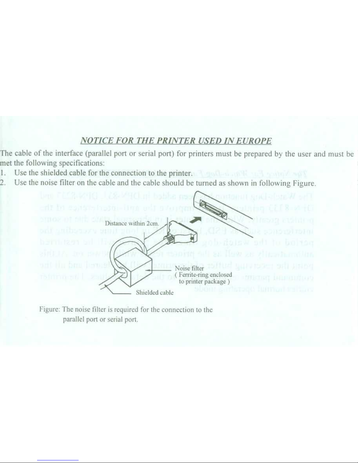
NOTICE FOR THE PRINTER USED IN EUROPE
The cable of the interface (parallel port or serial port) for printers must be prepared by the user and must be
met the following specifications
:
1.Use the shielded cable for the connection to the printer
.
2.Use the noise filter on the cable and the cable should be turned as shown in following Figure
.
Noise filter
(
Ferrite-ring enclosed
to printer package
)
Figure
: The noise älter is rquired for the connection to the
parallel port or serial port
.
Page 6
The Notice For Watch-Dog Function in DPN-833/8233/8333 Printer
The Watch-Dog function has been added in DPN-833, DPN-8233 and
DPN-8333
p
rinters
. ltwill improve the anti-interference of the
printers greatly
. When the printer is in abnormal state due to some
interference such as ESD, Burst or RF in long time exceeding the
period of the watch-dog timer, the printer will be restarted
automatically as well as the printer resets while power on
. At this
point the receiving buffer of the printer will be cleared and all the
command parameters will be set to the default values
. The printer
entries normal operating mode
.
Page 7
CONTENTS
Introduction
~
1
Chapter 1 Features and Specifications
1
.1 Features
~
1
1
.2 Nomenclature
~
2
1
.3 Specifications
~
2
Chapter 2 Installation
2
.1 Model Checking
~
4
2
.2 Accessories Examination
~
5
2
.3 Install Ribbon Cassette
~
5
2
.4 Loading Paper
~
9
2
.5 Power Supply
~
11
Chapter3Operation
3
.1 Parallel Interface Connection
~
12
3
.2 Serial Interface Connection
~
13
3
.3 Indicators and Switches Operation
~
17
3
.4 Self-Test
~
18
3
.5 Printer Initialization
~
18
Chapter 4 Printing Commands
4 .1 Summary
~
19
4
.2 Paper Feeding Commands
~
20
4
.3 Formatting Commands
~
21
4
.4 Character Setting Commands
~
26
4
.5 User-Defined Characters Commands~31
4
.6 Printing Graphics Commands
~
33
4
.7 Initialization Command
~
36
4
.8 Data Control Commands
~
36
4
.9 'Hexadecimal Dump Printing Command
. .
. 38
Chapter 5 Printing Examples
5
.1 Parallel Port Printer
~
39
5
.2 Serial Port Printer
~
40
Chapter 6
Operating Note
~
42
Appendix A
DIP
Switches
~
43
Appendix B Character Code Tables
~
44
Appendix C Printing Command Codes
~
46
Appendix D Parallel Interface and Operation
~
48
-I-
Page 8
Warning
!
The power supply of DPN-833/8233/8333 series printer is
only DC +5V
.
Never use AC mains
!
Appendix E
Serial Interface and Operation
~
49
Appendix F
Option List
~
511
Appendix
G
Printer Outline
~
51
Page 9
Introduction
DPN-833/8233/8333 is a new series of fast speed, general
purpose Impact dot matrix microprinter
. All members of this
series are small in size
,
light in weight
,
attractive in appearance
and easy in operation
.
The special features ofthis series are fast Speed and high
reliability
. This is the advantages of new hardware and
software design
. An 8-pin shuttle impact print head is adopted
.
Also Fast Paper Feed Function
-
twice the speed of printirg
-
is added
.
A font of 448 characters in the intenial ROM includes
IBM* Character Set # 2, also Greek, German, French,
Russian, Japanese and Chinese characters, math symbols,
specific meaning symbols and tabulation symbols
. Forty
print commands include Graph
. Table, Curve
. Most of these
are compatible with the ESC/P standard
.
DPN-833, 8233 & 8333 come in three types with different
numbers of characters per line (24,40 or 42 characters / line
)
and two interfaces (parallel
,
compatible with CENTRONICS
,
and serial compatible with RS -232C
.)
DPN-83 3/8233/83 33 printers are coinpetent as the output listing
•
~
Reginered
-d-.kof mht
devices for many kinds of intelligent Instrument and microcomputer
DPN-8333 series is designed especially for those applications which
need fast speed and small size
,
such as Point-Of- Sale System
,
Electronic Cash register and automatic recorder
.
Chapter 1
. Features and Specifications
1
.1 Features
Impact dot matrix printing Can print two paper
. (only for DPN-
8233/8333 series
)
4,6,or8-pin shuttle type print head
. Compact size
.
Different types with 24
,
40 or 42 characters /line
.
Fast printing Speed-2
.5
, 1
.9 or 1
.5 lines / sec respectively
,
and
Fast paper feed speed-twice of printing speed
.(only for DPN-
8333 series) Use plain paper roll, internal
.
40 printing commands, compatible with ESC/P standard
.
Besides Characters in ROM, user can define up to 32 user-
defined characters of 6 x 8 dot matrix
.
Two control keys for On/Off line control and Paper Feed
.
Two LED indicators for Power On and
On/Offline
.
Self-Test function
.
CMOS devices are adopted . Lower power consumption
and better interference resistance
.
Power-down and Wake-up automatically
. Minimize
power comsumption when printer is not in the
printing status
.
-
1 -
Page 10
1
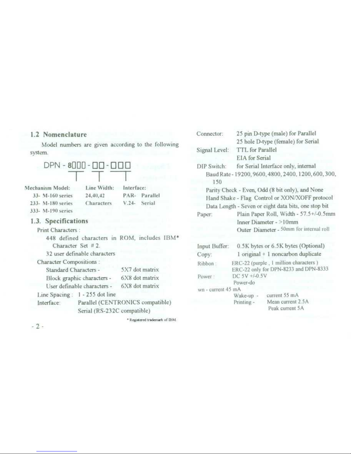
.2 Nomenclature
Model numbers are given according to the following
system
.
DPN
-
8000-0~ -990
I
Mechanism Model
:
~
Line Width
:~Interface
:
33- M-160
series
~
24,40,42
~
PAR-
Parallel
233- NI-180
series~Characters~x'24- Serial
333- M-190
series
1 .3
. Specifications
Print Characters
:
448 defined characters in ROM, includes IBM*
Character Set N 2
.
32 user definable characters
Character Compositions
Standard Characters
-
5X7 dot matrix
Block graphic characters-6X8 dot matrix
User definahle characters-6X8 dot matrix
Line Spacing
. 1 -
255 dot line
Interface
:
~
Parallel (CENTRONICS compatible)
Serial (RS-232C compatible)
-
RewaardUk
.-k of IBM
.
-2-
Connector
:
~
25 pin D-type (male) for Parallel
25 hole D-type (female) for Serial
Signal Level:TTL for Parallel
EIA for Serial
DIP Switch
:~for Serial Interface only, internal
Baud Rate-19200, 9600, 4800, 2400, 1200, 600, 300,
150
Parity Check -
Even, Odd (8 bit only), and None
Hand Shake-Flag Control or XON/XOFF protocol
Data Length -
Seven or eight data bits, one stop bit
Paper
:
~
Plain Paper Roll, Width -
57
.5+/-0
.5mm
Inner Diameter -
> 10mm
Outer Diameter
-
50nun ler mlernal roll
Input Buffet:0 .5K bytes or 6
.5K bytes (Optional)
Copy
:
1 original + 1 noncarbon duplicate
Ribbon
~
ERC-22 (purpte, 1 million characters
)
ERC-22 only for DPN-8233 and DPN-8333
Power
~
DC 5 V +/-0 5 V
Power-do
wn-current 45 mA
Wake-up
-~current 55 mA
Printing
-
~
Mean current 2
.5A
Peak current 5A
Page 11
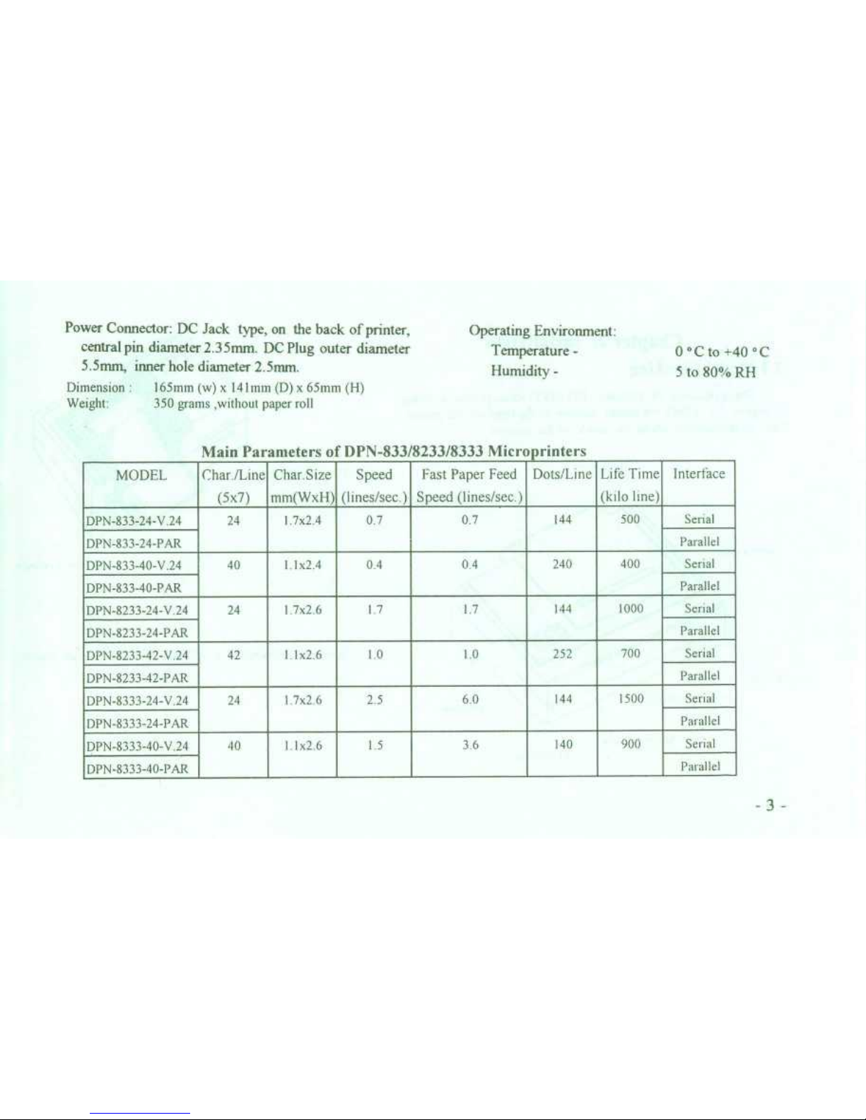
Dimension:165mm (w) x 14hmn (D) x 65mm (H)
Weight
:
~
350 grams ,without paper roll
Main Parameters of DPN-833/8233/8333 Micro rinters
-3-
MODEL
Char /Line
(5x7)
Char Size
mm(WxH)
Speed
(lines/sec
.)
Fast Paper Feed
Speed (1ines/sec
.)
Dots/Line Life Time
(kilo Itn
)
Interface
DPN-833-24-V
.24
24
1 7 2 4
0
.7
0
.7
144
500
Serial
Parallel
DPN-833-24-PAR
DPN-833-40-V
.24
40 1 1x24 0
.4 0 .4
240 400
Serial
Parallel
DPN-833-40-PAR
DPN-8233-24-V
.24
24
1 7x2 6
1
.7
1
.7
144
1000
Serial
Parallel
DPN-8233-24-PAR
DPN-8233-42-V 24
42 1 1x26
1
.0
1
.0
2)2 700
Serial
Parallel
DPN-8233-42-PAR
DPN-8333-24-V
.24
24
1 7x2 6
2 .5
6 .0
144
1500
Serial
Parallel
DPN-8333-24-PAR
DPN-8333-40-V
.24
40
11x26
L5
3,6 140
900
Senal
Parallel
DPN-8333-40-PAR
Power Connector
: DC Jack type, on the back of printer,
central pin diameter 2
.35mm
. DC Plug outer diameter
Operating Environment
:
Temperature
-
0 ° C to +40 ° C
5
.5mm, inner hole diameter 2
.5mm
.
Humidity
-
5 to 80% RH
Page 12
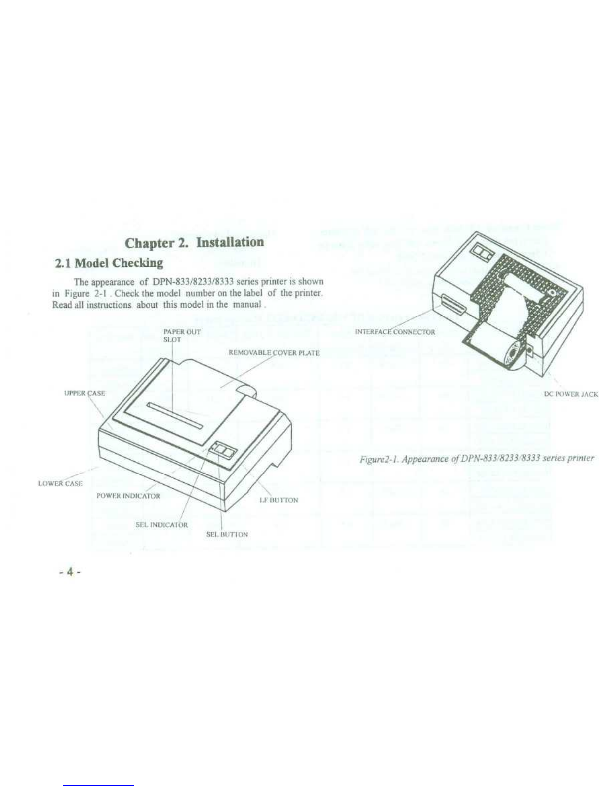
Chapter 2
. Installation
2
.1 Model Checking
The appearance of DPN-833/8233/8333 series printer is shown
in Figure 2-1.Check the mode) number on the label of the printer
.
Read all instructions about this model in the manual
.
PAPER OUT
~
INTERFACLcCONNCCTOR
SLOT
SEI
. MIT-ION
DC PU W I ii LACK
Figure2-l
. Appearance
of DPN-833/8233 8333 series printer
Page 13

2 .2
Accessories Examination
.A paper roll and a ribbon cassette have been loaded inside
the printer before packing
. A user's manual is included
.
The user may select optional accessories according to their
needs (see Appendix F)
.
2
.3 Install
Ribhon Cassette
Ribbon cassette has been put inside the printer before packeng
When the printing becomes faint after long use , put in a new
ribbon cassette
. The removable cover plate must be removed
while inserting a new ribbon cassette
. Following pictures show
how to remove it
Figure 2-2
. Correct action
.
1
. Push forward the removable Cover Plate with both
thumbs
. (Note the arrow on Cover Plate
. See Figure 2-2 and
Figure 2-3
.) Then take off Cover Plate carefully
.
Figure 2-3
. Incorrect action
-
wrong direction-
-5
-
Page 14
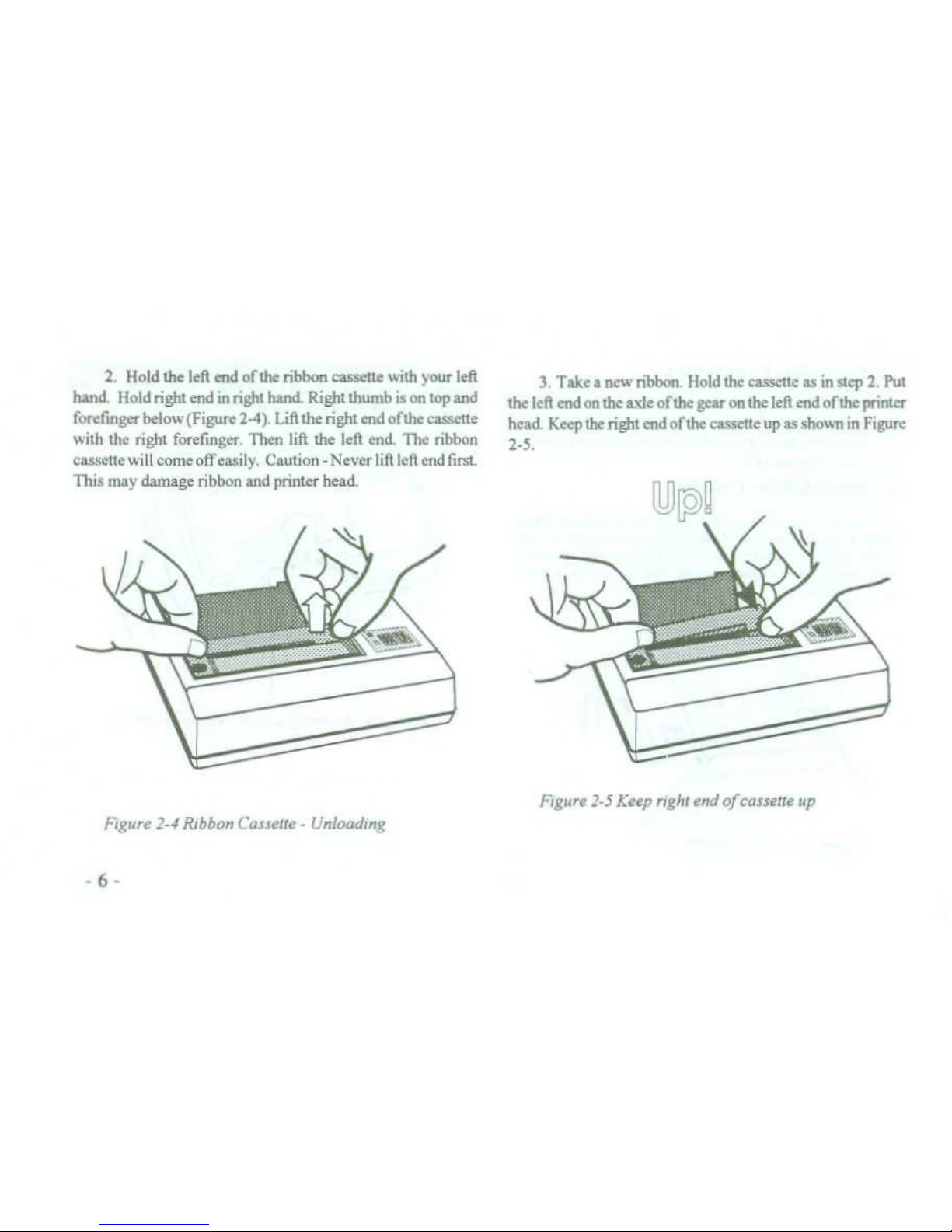
2
. Hold the left end of the ribbon cassette with your left
hand
. Hold right end in right hand
. Right thumb is on top and
forefmger below (Figure
2-4)
.
Lift the right end ofthe cassette
with the right forefinger
. Then lift the left end
. The ribbon
cassette will comeoffeasily
. Caution- Neverliftleftendfirst
.
This may damage ribbon and printer head
.
Figure 2-4 Ribbon Cassete-Unloading
3
. Take a new ribbon
. Hold the cassette as in step 2
. Put
the left end on the axle ofthe gear on the left end of the printer
head
. Keep the right end ofthe cassette up as shown in Figure
2-5
.
Figure 2-5 Keep right end of cassette up
Page 15
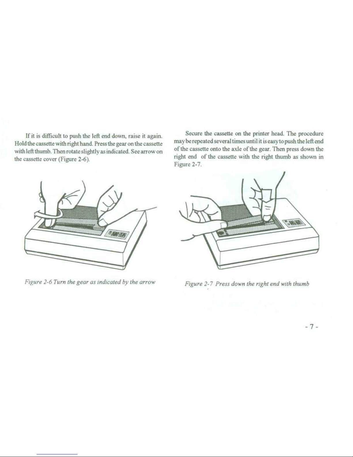
If it is difficult to push the left end down, raise it again
.
Hold the cassette with right hand
. Press the gear on the cassette
with left thumb
. Then rotate slightly
as indicated . See arrow on
the cassette cover (Figure
2-6)
.
Figure2-6 Turn the gear as indicated by the arrow
Secure the cassette on the printer head
. The procedure
may be repeated several times until it is easyto push the left end
of the cassette onto the axle of the gear
. Then press down the
right end of the cassette with the right thumb as shown in
Figure 2-7
.
Figure 2-7 Press down the right end with thumb
Page 16
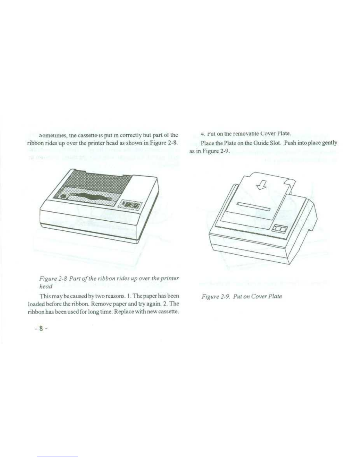
aometimes, tne cassette is put m correctly but part ot the
~
w
. Put on tne removable Lover Plate
.
ribbon rides up over the printer head as shown in Figure
2-8
.
~
Place the Plate on the Guide Slot . Push into place gently
as in Figure 2-9
.
Figure 2-8 Part ofthe ribbon rides up over the printer
head
This may be caused by two reasons
. 1
. The paper has been
loaded before the ribbon
. Remove paper and try again
.
2
. The
ribbon has been used for long time
. Replace with new cassette
.
-8-
Figure 2-9
. Put on Cover Plate
Page 17
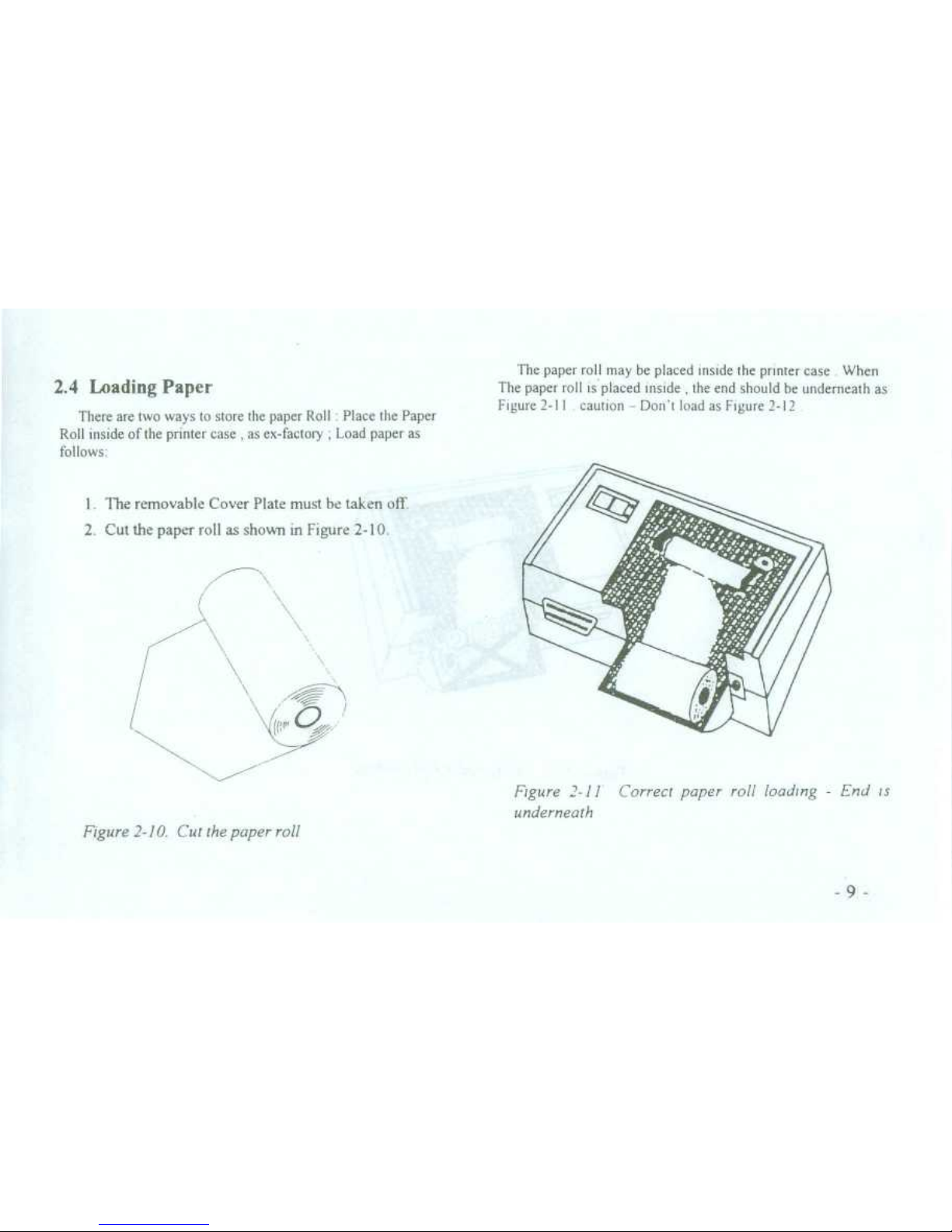
2.4Loading Paper
There are two ways to store the paper Roll
:
Place the Paper
Roll inside of the printer case
,
as ex-factory
, Load paper as
fol lows
:
1
. The removable Cover Plate must be taken off
2
. Cut the paper roll as shown in Figure 2-10
.
\/
Figure 2-10
. Cut the paper roll
The paper roll may be placed inside the printer case When
The paper roll is placed inside
,
the end should be underneath as
Figure 2-11 caution Donl load as Figure 2-12
Figure 2-11 Correct paper roll loading -
End is
underneath
9
Page 18
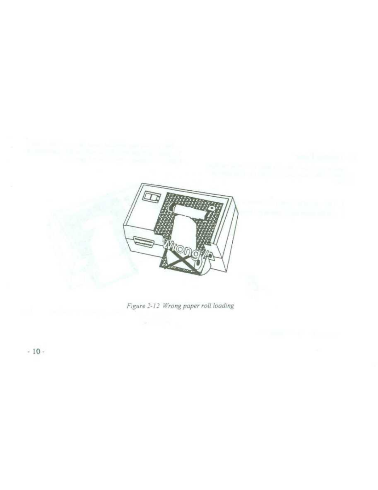
Figure '-1? Wrong paper roll loading
Page 19
3.Power an 5 b' power supply
.
4
. The SEL (select) Button is an ON/OFF toggle
.
press to
the SLL
. indicator off Then press
1-f-'
(Line Feed)butlon,Ihn printer
head begins to nm
Feed in paper.The paper entern the printer head
and coroes out fiom the top of the printer head
.
To stop paper feeding
release LF button
.
5
. Then press and release LF or SEL
. Or switch offthe
power supply
6
. Feed the paper through the slot on the removable Cover
Plate
. Then push the plate back on the printer as before
.
(See
Section 2
.3 Step 4
)
2
.5 Power Supply
The DPN-833/8233/8333 series printer uses a 5V DC power
supply.A power supply is specially made for this series and
is
recotntnended in Appendix F
. Insert the output plug of the power
.supply into the jack on the back of the printer
.
When using other
models of power supply, please pay attention to the voltage and
current limits
.If the voltage is higher than
DC5.SVor lower than
DC 4 5V, or the maximumm cunent is less than SA,the printer will
not work normally and the printer head may be damaged
.
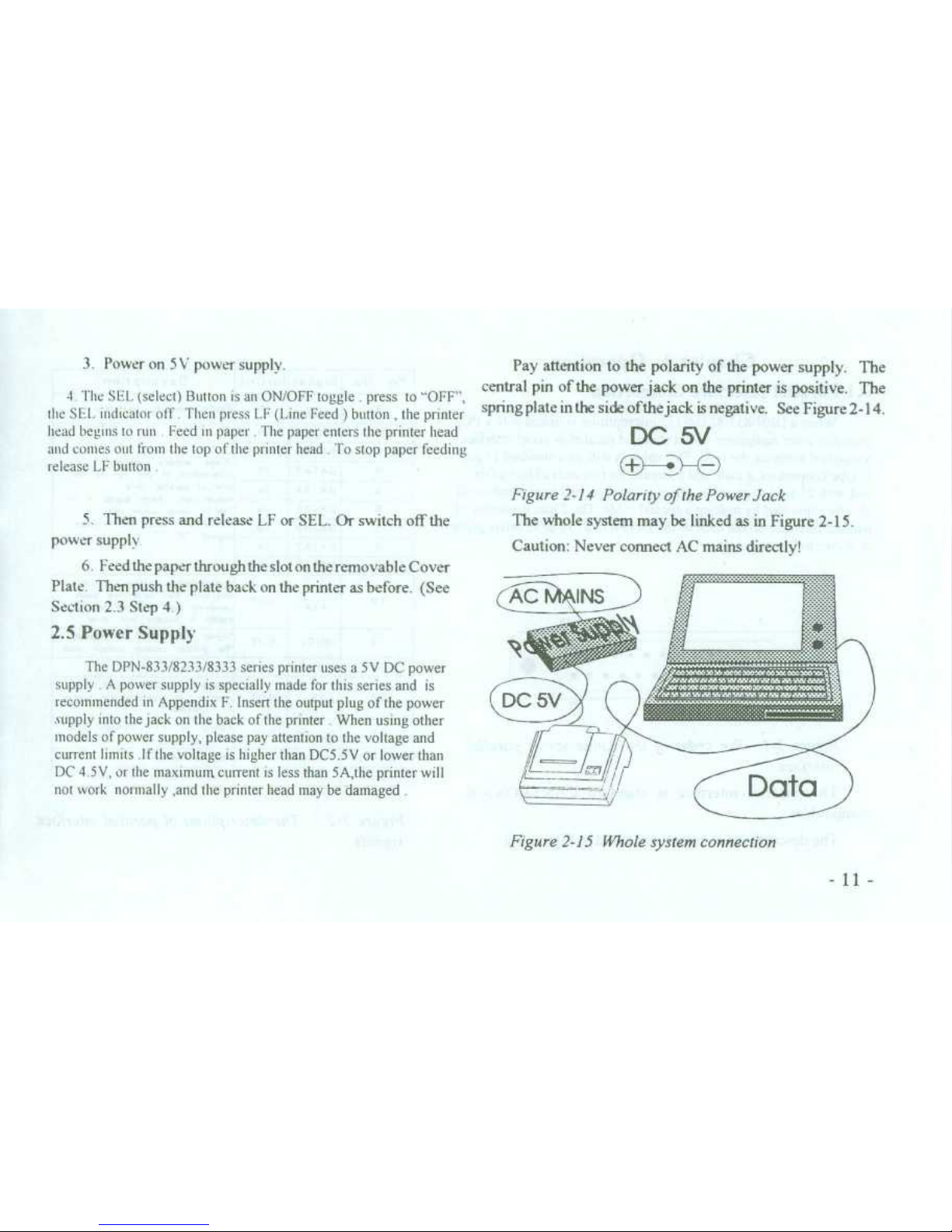
Pay attention to the polarity of the power supply
.
The
central pin ofthe power jack on the printer is positive
.
The
sptingplate in the side ofthe jack is negative
.
See Figure 2-14
.
DC 5V
G
_'ZJ
Figure 2-14 Polarity ofthePowerJack
The whole system may be linked as in Figure 2-15
.
Caution
: Never connect AC main directly!
Figure 2-15 Whole system connection
Page 20
Chapter 3
. Operation
3
.1 Parallel Interface Connection
When a DPN-833/8233/8333 microprinter is linked with a PC,
laptop,or other equipment with a standard parallel or serial interface,
a standard cable can be used
. This cable is with two standard 25 pin
D type connectors, a male and a female, on two ends of this cable,
and with 25 wire connectoon Other computers and equipment could
also be connected by making a special cable The 25pin connector of
parallel Interface on the back of the DPN-833/8233/8333 series printer
is shown in Figure 3-1
.
-12-
i
14
25
13
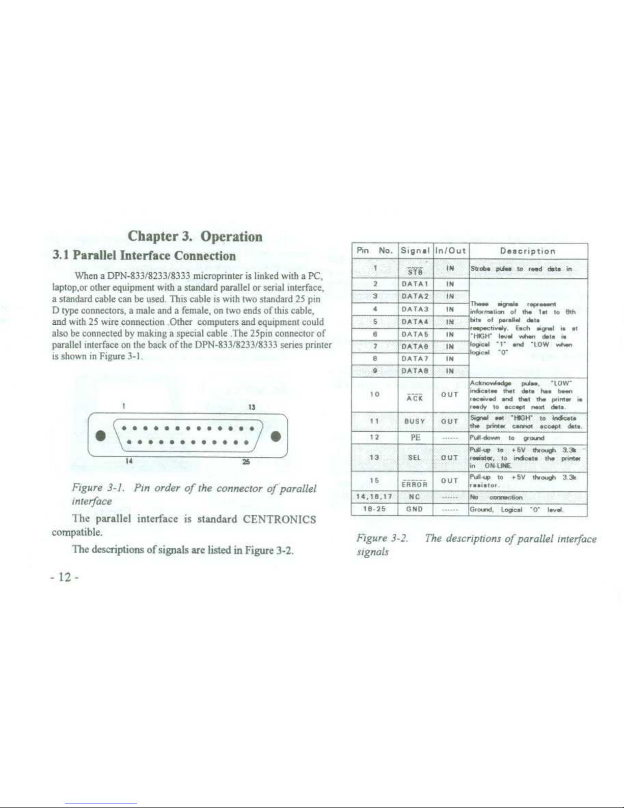
Figure 3-1
. Pin order of the connector of parallel
interface
The
parallel interface is standard CENTRONICS
compatible
.
The
description of signals are listed in Figure 3-2
.
Figure 3-2
.
~
The description of parallel interface
Signals
PinNo.
Signal In/Out
Description
STB
IN
SOaw>pha tn r
.ad data, in
DATA 1
IN
3
DATA2
IN
4
I
DATA3
Thea.egal.r
.peasa
;nformeti ,
of the 1at to 8th
at
. of p
.r&Bai dt
.
re
.pedivaly
6ch
iga1 i
et
'HIGH' Iavd when date i
1.}.
.i
'1"
.nd "LOW whan
logt&-o
-
8
DATA4
DATAS
1
IN
7
DATAS
IN
8
DATA?
IN
DATAS
IN
10
ACK
OUT
Acknnod
.dp" pa..,
'LOW'
indic
.t .
. that 6t
. h.. bass
.i .
.d
and tlat tfa pintx i
.
rad
y to
.co
.pt na.tda-
11
BUSY
OUT
s„>n&
rat '#GH'~Lxic
.t .
tM
>IN«
--otaec.pt
date
.
12
PE
PJ1
.dow,togovd
13
SEI
0UT
P.ü,y ta +5V".«
.d,,
3-3k
-
aeas, to in6gta ih
. pitds
in
ON-LINE
15
ERKOR
PJI-w to
+5V thoug, 3
.31,
r..i
.tor-
1 4 18 1 7
N C~i
~
No
~tlan
18 25
GND
G--d
. Loglc.I'0'1..i
Page 21

Signal level is TTL standard
.
The signal timing chart of parallel interface is shown in
Figure 3-3
.
BUSY
ACK
DATA
STB
05Ns
(MIN
.)
0-5µs
(MIN
.)
05µs (MIN
.)
~
I
\\
t~
~
~
-
VApprox.5 us
Approx
.
5 p s
Figure
3 -3
. Signal tinung chart of
parallel interface
3
.2 Serial
Interface Connection
The cable mentioned in Section 3
.1 also can be used to
link printer with computers or equipment with standard RS232C interface
.
The 25 hole connector an the back of the DPN-833/82 ,3833 3
senes printer is shown in Figure 3-A
13
.
.......
. ...
i
Figure 3-4
. Hole order of the connector of serial
interface
The serial interface is standard RS-232C compatihle
.
The description of Signals are listed in Figure 3-5
.
Page 22

Figure 3-5. The description ofserial interface signals
Signal level is compatible with EIA Standard
.
The Baud Rate of serial interface can be selected as
150, 300, 600, 1200, 2400
. 4800
. 9600 or 19200 bps
. It
can be set with internal DIP switches as required
. To set
the Baud Rate, take off the removable Cover Plate and the
upper case of the printer
. You can see the DIP switch in
the upper right corner of the PCB
. Baud Rate can be
selected as inFigure3-7
. SwitchnearthewhitemarkisKl
.
The setting is KI ON, K2 OFF, K3 OFF ex-factory
. i.e.
9600 bps
. (See Figure 3-6
.)
ON
Z
Z
Z
. Z
1~2 3 4 5
a
6
Figure 3-6
. DIP switch ex factory setting
Pln
No
.
Signal
Source
Description
TxD
Host
Printer receives data from
host computer
3
RxD
Printer
Printer trasmits data when
uses the handshaking of
X-ON/X-OFF
CTS
Pnr[ter
Signal sets "MARK" state to
indicate the printer is BUSY
and can not accept data,
and "SPACE" state to
indicate the printer is ready
and can accept data
.
6 DSR
Printer
Signal sets "SPACE" to
indicate the printer is
ON-LINE
GND
Signal Ground
8
DCD
Printer
Same as CTS
Page 23

Figure 3-7 Baud Rate selection
The format ofserial interface is asynchronous as shown in
Figure 3-8
.
Start Bit (0)~Date Bits
~
Parity Bit~Stop Bit (1)
1 bit
~
7/8 bits
~
1 bit
~
1 bit
Figure 3-8
. Asynchronous transmitting format
START bit and STOP bit are one bit Signals
. These
signals come atthe beginning and end ofa computer message
.
The computer message, the DATA, has seven or eigut bits,
plus a Parity Check bit
. The Data bits and Parity Check can
be set with K5/K6 switches as in Figure 3-9
. These are set
at 8 bits/Non Parity
ex-factory, K5 ON,
K6 ON
.
Figure 3-9
. Data bits and Parity selection
-15-
DIP SWITCH
PARITY
öDDD~∎
00000EI
S-NON
ÖDOD~L7
ooDDO∎
8-ODD
D
D D
o
D∎
DoED
•o
8-EVEN
ö
0 0 0 0 0
oDOO~∎
7-EVEN
DIP
SWITCH
BPS
ON
∎
•U
ooo
000000
150
2 3
•
6 6
ON
o
•U
aoa
∎70700
300
1~2
x
•
5~6
i7Z77a
0
•0
070
7 J
•
6 6
600
OM
07x777
∎7770
1200
1x6
•
s e
oN
∎
.7777
07770
2400
2 2
•
6 6
ON
7
•0
000
∎72777
4800
1~0
~ .
s s
7~~000
9600
1 2 3
•
5 6
ON
700700
∎x3777
19200
1 2 3, 6 6
Page 24

The signal polarity of serial RS-232C is
:
Mark = Logic "1" (EIA low level
. -3V to -27V)
Space = Logic "0" (EIA high level
. +3V to +27V)
There are two kinds of Handshaking to be selected
.
First is the Flag Control
. The other is the X-ONIX-OFF
p
rotocol
. l
t
is selected with K4 as in Figure 3-10
.
The K4
is set to OFF ex-factory
.
DIP
SWITCH
1DD
•E
0
000000
X111030
000 UDO
HANDSHAKING
FUG
XON/XOFF
Figure 3-10
. Handshaking selection
Two kinds of Handshaking are listed in Figure 3-11
.
-16-
Figure 3-11
. Two kinds of Handshaking
The operation procedure of serial interface is shown as
follows
:
(1) Select Baud Rate with switches Kl -
K3
.
(2) Select Data bits and Parity with switches K5
-K7.
(3) Select Handshaking with switch K4
.
(4) When only 32 bytes free space is left in the printer
buffer
. signal DCD (line 8) and CTS (line 5) are both set
to "busy", i.e. Mark status, by printer
.
Otherwise set to
"ready", i.e. Space Status
.
(5) Under X-ON/X-OFF control Handshaking
.
the
printer sends X-OFF code (13 in Hex
.) when it is busy,
sends X-ON code (11 in Hex
.) when ready
.
(6) Under Flag control Handshaking, host computer
sends data to printer when both DCD and CTS are ready
.
Hatdsha~g
DAta Dircction
RS 232 lntcrfacc's Signal
Flag Control
Can accep data
Lire 5 & 8 a n SPACE stete
Can't accept data
Line 5 & 8 arc MARK
statt
X-ON/X-OFF
Control
Can accept
data
Send X-ON code (1 IH) an
lim
3
Can't accept data
Send X-OFF code (13H) an line 3
Page 25

3
.3 Indicators and Switches Operation
There are two indicators and two button switches on the
panel of the printer
.
The power indicator is labelled
"P.".
The other is the "SEL" indicator
. A button switch is labelled
"SEL" for selecting On/Off Line
. Aother is labelled "LF" for
paper Line Feeding
. (See Figure 3-12
.)
∎
®
SEL
SEL
Figure 3-12
. Indicators and switches
On/Off-Line Status is indicated by the green SEL LED
.
When the indicator is On the printer is On-Line
. The SEL
button changes this status
.
Three working mode
-
Self-Test, On/Off Line and Paper
Feed are selected by SEL and LF buttons
.
1
. Self-Test Mode
There are two ways to enter the Self-Test mode
.
(1) When Power On Pmss S EL button for a few seconds,
then release
. The SFI, indicator then tums off and thc
printer prints out Self-Test sample
.
(2) With Power On and printer Off-Line, press and
holdLFand thenpress SEL
. Release both buttonstogether
.
The printer will enter Self Test mode
There are also two ways to exit the Self-Test mode
.
(1) The printer will exit Self-Test mode automatically
after printing the Self-Test sample
.
(2) When the Self-Test Sample is being printed, it can be
tenninated by pressing the SEL button
.
2
. On/Off Line Mode
After switching on or exiting from the Self-Test mode, the
printer entern On-Line mode
. The SEL indicator lights up
.
Press the SEL button, SEL indicator goes off Printer enters
Off Line mode and can not receive data
. Press SEL again
.
Printer re-enters the On-Line mode
.
SEL has another function
-
to interrupt the printout
. If
SEL is pressed and then released during a printout, the printer
will stopaft
.ercompletingthecurrentline
. Atthispointyoucan
feed more paper
. To complete the printout, press and release
SEL button The printer will run again at the point printout
was interrupted
.
-17-
Page 26
3
. Paper Feed Mode
When print procedure is interrupted, SEL off, the printer enters
Off-Line mode
.If paper has tobe replaced press LF button Printer
will feed paper without printing then release LF, printer will stop
paper feed
. Press SEL, printer re-enters On -Line mode
.
3
.4 Self-Test
Self- Test cheeks condition of printer
. lf the printer prints out
the Self-Test sample correctly lt is working normally
. Eventually
faults are not caused by the printer but by the interface on host
computer
.lf Self- Test does not tun or print out a faulty sample
,
check power supply If power is OK
,
the printer itself requires
attention
Self-Test prints out all characters in the fonts
. Then prints the
messaltes about interface type and printer head mode[
.
After Self-fest the printer enters On-Line
m
ode
. ltcan then
Receive data from the host computer
.
3
.5 Printer Initialization
Initialization includes default value settings
. Default
values are
: 3 dot line spacing, 40 lins Form length, 0 values
of vertical tab and horizontal tab, 0 values ofright margin and
left margin, normal alphanumeric and graphic character size
(i.e.
enlarge factor is 1)
. Initialization clears all user defined
characters and data in printing buffer, and selects character set
1, then sets printer to On-Line mode, i
.e
. ready to receive
commands and data
.
There are three ways to realize Initialization
.
First
-
run Initialization software on master computer
.
Master computer sends Utitialization command (ESC
L)
to
printer
.
Second
-
through Self-Test procedure
.
Third-power on Initialization
.
Page 27
Chapter 4
. Printing Commands
4
.1 Summary
DPN-833/8233/8333 provides up to 40 printing commands
These command special functions
(1) Defme formatting
.
(2) En large or condense of characters
.
(3) Print image graphics
.
(4) Select font
.
(5) Define special characters
.
(6) Other
.
Some of these commands consist of a one byte control
code
. Some are ESC code sequences
. The latter sequences
start with "ESC" code, followed by other alphanumeric
characters
.
Printer's control codes (especially ESC control codes) are not
standardized Every printer manufacturer has his own code system
.
Control codes for the DPN-833/8233/8333 series were designed with
reference to the popular pnnter
.Hence ,they are compatible with most
printers
.
Printing commands are described under five headings set
out below
:
Code Sequence
Function
Format
Explanation
Example
Code Sequence
~
Fundion
Format
: ASCII:the sequence in standard ASCII characters
Decimal
:
the sequence in decimal numbers
.
Hexadecimal
: the sequence in hexadecimal numbers
.
Explanation
:
A description of the effect of issuing the command, i
.e
.
what the command does
.
Example
:
Some program examples are listed to illustrate the
commands
.
Page 28

Explanation
:
Feed one line forward
.
ESC J
Format
: ASCII:ESC J
n
Decimal
: 27
74
n
Hexadecimal
: 1B
4A n
-
2
0
-
Perform Dot-Line Feed
Explanation
:
Immediate Line Feed for n dot lins without Caniage Retum
.
The value of n can be any number in the range 1
-
255
.
Explanation
:
The line spacing is set to n dot-lins for future Line Feed
commands
.
The value of n can be any number in the range 1
-
255
.
Normal settings are n=0 for ESC K Bit Image printing mode
and n=3 for text printing mode
.
Example
:
The BASIC program for this command is shown below
:
10 FOR I=1 TO 11 STEP 2
20 LPRINT CHR$(27)
;" 1'
;CHR$(I)
;
`ESC 1, set line spacing
Theseprintingcommandsareintroducedbelowaccording
to the type of function they perform
.
Enlarge character commands ESC Vor ESC W (refer to
Section 4
.4) enlarge line spacing and consequently change the
value of any following ESC J command
.
4
.2 Paper Feeding Commands
LF
Line Feed
ESC 1
Set line spacing
Format
: ASCII:LF
Format
: ASCII
: ESC
1
n
Decimal:10
Decimal
: 27
49
n
Hexadecimal
: OA
Hexadecimal
: 1 B
31 n
Page 29
Explanation
:
Feed paper to the beginning position of next page
.
ESC N
~
Set bottom margin
FF
~
Form feed
Format
: ASCII:ESC N
n
Format
: ASCII
: FF
~
Decimal:27
78
n
Decimal:12
~
Hexadecimal
: I B
4E n
Hexadecimal
: OC
Explanation
:
The bottom margin is set to n lines The value of n should be
within the Tange 0 to 255
.Default value n=0
.ln DPN-8333, the bottom
margin is the spacing between the last line of a page and the first line
of the next page
.
-21
-
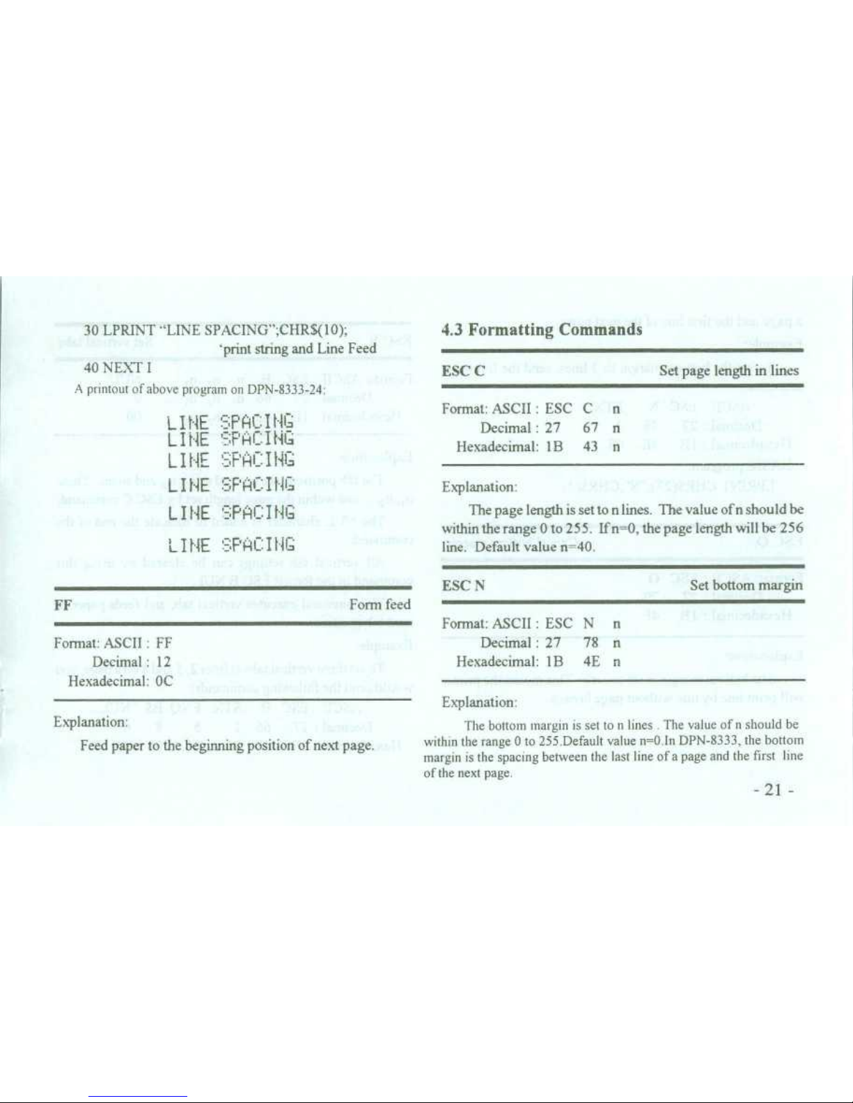
30 LPRINT "LINE SPACING"
;CHR$(l0)
;
4
.3 Formatting Commands
'print string and Line Feed
40 NEXT I
ESC C
Set page length in lines
A
printout of above program on DPN-8333-24
:
L I NE '='
.PA I Flies
Format
: ASCII:ESC
Decimal:27
C n
67 n
L I NE
r'HL_ I NG
Hexadecimal
: 1 B
43
n
LIRE _P HI=ING
LIRE'=;F'i~l_ I GaG
L I NE = PHl_ I f 4G
Explanation
:
The page length is set ton lins
. The value of n should be
IRE '= F'HC I f IG
within the range 0 to 25 5
. If n=0, the page length will be 256
line
. Default value n=40
.
Page 30
a page and the first line of the next page
.
Example
:
To set the bottom margin to 3 lines, send the following
sequence
:
ASCII:ESC N ETX
Decimal
:27 78
3
Hexadecimal
: 1B
4E 03
BASIC program
:
LPRINT CHR$(27)
;" N'
;CHR$(3)
;
ESC 0
~
Cancel bottom margin
Format
: ASCII
: ESC 0
Decimal
:27 79
Hexadecimal
: IB 4F
Explanation
:
The bottom margin is set to zero . This means the printer
will print line by line without page breaks
.
ESC B
Set vertical tabs
Format
: ASCII:ESC
B
n, n2n3. . .
NUL
Decimal
: 27
66
n, nzn3...
0
Hexadecimal:I B
42
n, n;n3...
00
Explanation
:
The tab position are entered as n,, n
2,and so on
. These
n,, n
2 ,
. . .
are within the page length set by ESC C command
.
The NUL character is added to indicate the end of the
command
.
All vertical tab settings can be cleared by usit
.g this
command in the forthat ESC B NUL
.
VT command executes vertical tab, and teeds paper to
next tab position
.
Example
:
To set three vertical tabs at lines 2, 5 and 8 on a page, you
would send the following commands
:
ASCII:ESC
B
STX ENQ BS
NUL
Decimal
: 27
66
2
5 8 0
Hexadecimal
: 1B
42
02
05 08 00
Page 31
comsna
.n ~
.
-23-
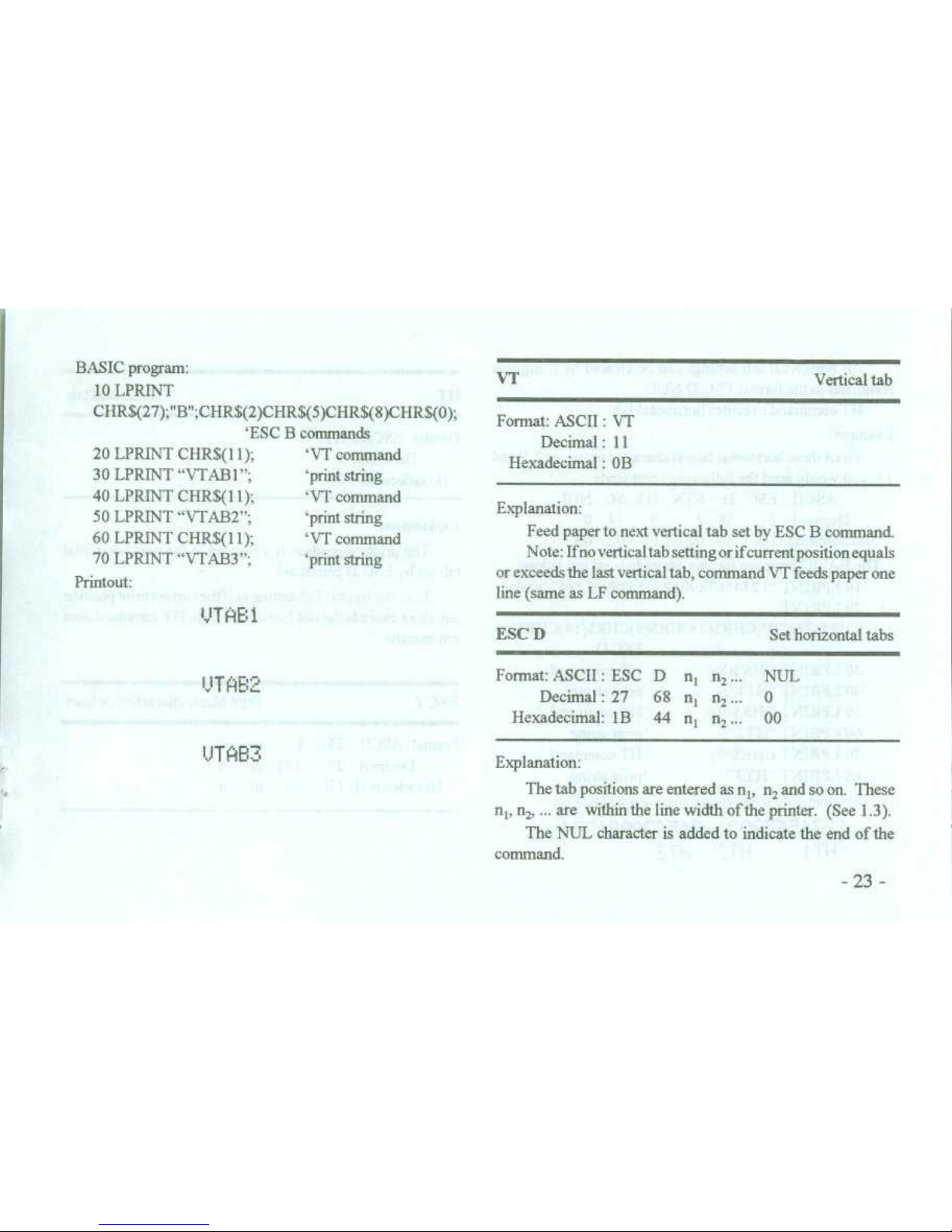
BASIC program
:
10 LPRINT
20 LPRINT CHR$(11),
30 LPRINT "VTAB1"
;
40 LPRINT CHR$(11)
;
50 LPRINT "VTAB2"
;
60 LPRINT CHR$(l
70 LPRINT "VTAB3'
;
Printout
:
CHR$(27)
;"B"
;CHR$(2)CHR$(5)CHR$(8)CHR$(0)
;
1)
;
'ESC B commands
`VT command
`print string
`VT command
`print string
`VT command
`print string
VT
~
Vertical tab
Format
: ASCII:VT
Decimal
: 11
Hexadecimal:OB
Explanation
:
Feed paper to next vertical tab set by ESC B command
.
Note
: Ifno vertical tab setting or ifcurrent position equals
or exceeds the last vertical tab, command VT feeds paper one
line (same as LF command)
.
VTHB i
ESC D
~
Set horizontal tabs
UTA
P-2-'
Format
: ASCII:ESC D
nin2. . .
NUL
Decimal
: 27~68 n, n2. .
. 0
Hexadecimal
: 1B
44 nin2. . .
00
VTHB3
Explanation
:
The tab position are entered as n
1
, n2and so on
. These
nl, n2, . . .
are within the line width ofthe printer
.
(See1.3)
.
The NL L character is added to indicate the end of the
Page 32
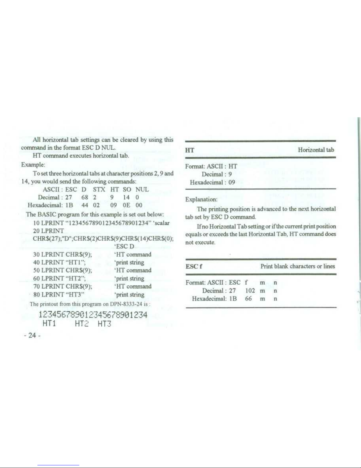
The printout from this program an DPN-8333-24 is
134 67
:9[112 3456789131`''4
HT1
~
HT_
HT3
-24
-
All horizontal tab settings can be cleared
command in the format ESC D NUL
.
HT command executes horizontal tab
.
Example
:
To set three horizontal tabs at character
14, you would send the following commands
:
by using this
positions 2, 9 and
HT
~
Horizontal tab
Format
: ASCII:HT
Decimal
: 9
Hexadecimal:09
ASCII:ESC D
STX HT SO NUL
Explanation
:
The printing position is advanced to the next horizontal
tab set by ESC D command
.
Ifno Horizontal Tab setting or ifthe current print position
equals or exceeds the last Horizontal Tab, HT command does
not execute
.
Decimal
: 27
68 2
~
9
Hexadecimal
: IB
44 02~09
14
0
OE 00
The BASIC program for this example is set out below
:
10 LPRINT "123456789012345678901234"`scalar
20 LPRINT
CHR$(27)
;'D'
;CHR$(2)CHRS(9)CHRS(14)CHRS(0)
;
`ESC D
30 LPRINT CHR$(9)
;
~
'HT command
40 LPRINT "HT1"
;
~
`print string
50 LPRINT CHR$(9)
;
~
'HT command
ESC f
Print blank characters or lines
60 LPRINT "HT2"
;
~
`print string
70 LPRINT CHR$(9)
;
~
'HT command
Format
: ASCII:ESC
Decimal
:27
f m
102 mnn
80 LPRINT "HT3"
~
`print string
Hexadecimal
: 1 B
66
m
n
Page 33

Explanation
:
If m=0, command ESC f NUL n will print n blank
characters
. The value n shouldbewithin the line width ofthe
printer (See Section
1
.3)
.
If m=1, command ESC f SOH n will print n blank lines
.
The value n shouldbewithin the range 0 to 255
.
Example
.
To print 6 space characters in the line, send the following
command
:
ASCII:ESC
Decimal:27
Hexadecimal
: 1 B
f
102
66
To print 6 blank lines
:
ASCII:ESC
Decimal:27
Hexadecimal:1 B
ESC Q
Format
: ASCII:ESC Q
n
Decimal
:27~81 n
Hexadecimal:1 B
51 n
NULACK
0 6
00 06
f
SOH ACK
102
1~6
66
01
06
Set right margin
Explanation
:
The value n should be within the line width ofthe printer
(See Section1.3)
.
Default value n=0 . No right margin
.
The command sets an absolute position and is not affected
by character enlarge command ESC U or ESC W
.
When the right margin is reached, a Carriage Retum and
Line Feed is added
.
Example
:
To set the right margin to 6 columns, send
:
ASCII:ESC Q ACK
Decimal
: 27 81 6
Hexadecimal:1 B
51
06
The BASIC program for this example is set out below
:
10 LPRINT "123456789012345678901234" 'scale
20 LPRINT CHRS(27)
;"Q"
;CHRS(6)
;
~
'ESCQ
30 LPRINT "123456789012345678901234567890"
Pnntow on DPN-8333-24
1'2 4`G7
:
-
;
;'?N12?45t
"
'~i
t1
2
4
-25
-
Page 34

ESC 1
~
Set left margin
10 LPRINT "123456789012345678901234" 'scale
20 LPRINT CHRS(27)
;" 1"
;CHRS(6)
;
'ESC 1
30 LPRINT "123456789012345678901234567890"
-
2 6
-
Printout on DPN-8333-24
121
,17
4567
21W11
~
C91'234
10 FOR I=1 TO 3~'from 1 to 3 times
20 LPRINT CHR$(27)
;"U"
;CHR$(I)
;
'ESC U conunand
30 LPRINT "DPN°'
; `print string
Format
: ASCII:ESC 1
~
n
Decimal
: 27~108 n
Hexadecimal
: 1 B
6C
n
1 4567
•
tTJ12?45
'90112
--745--,7~:,
9 r
4
.4 Character Setting Commands
Explanation
:
The value n should be within the line width ofthe printer
(See Section1.3).Default value n=0
. This means no left
ESC U
Enlarge width
Format
: ASCII:ESC
U n
margin
.
Decimal
: 27 85
n
The command sets an
absolute position and is not
affected
by character enlarge command ESC U or ESC W
.
Example
:
To set the left margin to 6, you would send
:
ASCII
:
ESC 1~ACK
Decimal
: 27~108 6
Hexadecimal
: 1B
6C
06
BASIC program
:
Hexadecimal:1 B
55 n
Explanation
:
Characters or graphics following this command are print-
ed at n times normal width
. The value n should be in the range
1 to 4
. Default value n=1, i
.e
. normal width
.
Example
:
BASIC program
:
Page 35

40 NEXT I
50 LPRINT CHRS(13)
;
~
'CR command
Printout
:
Explanation
:
Characters or graphics following this command
are
printed at n times normal height . The value n should be within
the range 1 to 4
. Default value n=1, i
.e
. normal height
.
This command can only be set at the beginning of a line
.
Example
:
BASIC program
:
10 FOR I=l TO 3~`from 1 to 3 times
SOH (n=1, see ESC W in this section), i
.e
. Set height and
width to normal size before enlarging height ESC V
.
DFHC' P t-N Cm F`
i--a
20 LPRINT CHR$(27)
;"V"
;CHRS(I)
;
`ESC V command
Note
: ESC U will not function unless preceded by ESC W
30 LPRINT "DPN"
`print
40 NEXT I
Printout on DPN-8333-24
DFN
OPH
string
SOH (n=1, see ESC W in this section), i
.e
. Set height and
width to normal size before enlarging width ESC U
.
ESC V
Enlarge height
Format
: ASCII:ESC
Decimal
:27V86nn
[IN
Hexadecimal:1 B
56
n
Note
: ESC V will not function unless preceded by ESC W
Page 36
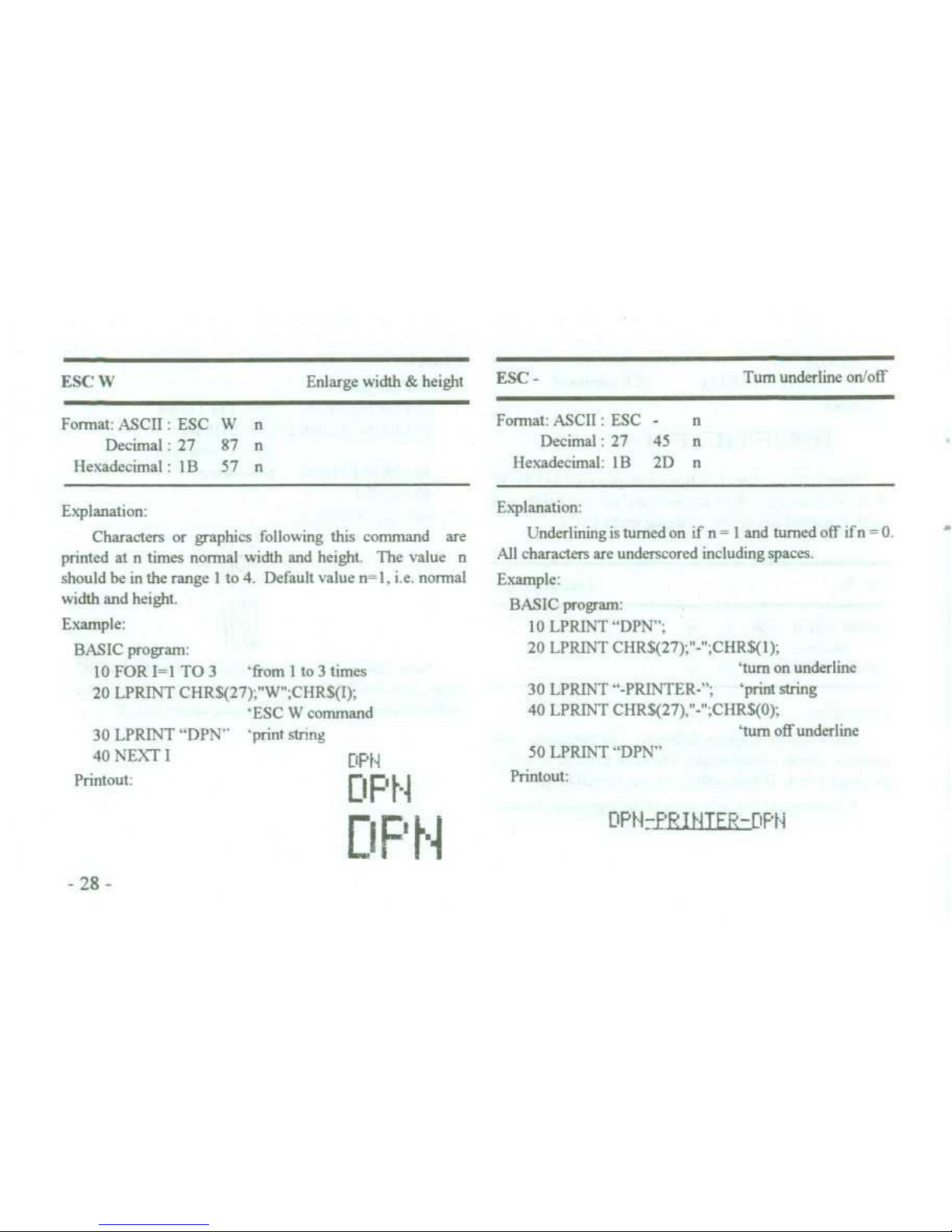
Explanation
:
Characters or graphics following this command
are
printed at n times normal width and height
. The value n
should be in the range 1 to 4
. Default value n=1, i
.e
. normal
width and height
.
Example
:
BASIC program
:
10 FOR I=1 TO 3
~
'from 1 to 3 times
20 LPRINT CHR$(27)
;"W'
;CHR$(I)
;
'ESC W command
30 LPRINT "DPN"
'print string
40 NEXT I
Printout
:
-
2
8
-
ESC
-
~
Turn underline on/off
DPN
0F't-a
DPN
Format
: ASCII:ESC
-~n
Decimal
: 27
45
n
Hexadecimal
: 1B
2D
n
Explanation
:
Underlining is tumed on if n = 1 and tumed off if n = 0
.
All characters are underscored including spaces
.
Example
:
BASIC program
:
10 LPRINT "DPN"
;
20 LPRINT CHR$(27)
;"-"
;CHR$(1)
;
'turn on underline
30 LPRINT "-PRINTER-"
; 'print string
40 LPRINT CHR$(27),"-" ;CHRS(0)
;
'rum off underline
50 LPRINT "DPN"
Printout
:
f' It-ITEE-DPf-i
ESC W
Enlarge width & height
Format
: ASCII:ESC
W
n
Decimal
: 27
87
n
Hexadecimal
: 1B
57
n
Page 37

ESC 6
Format
: ASCII:ESC 6
decimal:27
54
Hexadecimal
: I B 36
50 LPRINT "DPN"
Pnntout
:
DPNd-PF
:IHHTEF,-DPN
Select Font 1
Explanation
:
~
Explanation
:
Overscoring is tumed an if n=1 and tumed off if n=0
.
~
Characters following this command are printed usingthe
All characters are overscored including spaces
.
~
Font 1 (See Appendix B)
.
Example
:
~
There are two fonts available in the DPN-833/8233/8333
BASIC program
:
~
printer
. Font 1 is selected at power on or an ESC
(ei,
command
.
10 LPRINT "DPN"
;
20 LPRINT CHRS(27)
;"+"
;CHRS(1)
;
~
ESC 7
~
Select Font 2
'turn an overscore
30 LPRINT "-PRINTER-";'print string
~
Format
: ASCII:ESC 7
40 LPRINT CHRS(27),"+",CHRS(0)
;
~
decimal:27
55
'turn off overscore
~
Hexadecimal
: 1 B 37
Explanation
:
Characters.following this command are printed using the
Font 2 (See Appendix B)
.
Also see ESC 6-
-29
-
ESC +
Tum overscore on/off
Format
: ASCII:ESC
+
n
Decimal
: 27
43
n
Hexadecimal
: I B
2B
n
Page 38

SO
~
Select double-width printing for one line
Format
: ASCII
: SO
decimal:14
Hexadecimal
: OE
Explanation
.
Characters following this command on the same line ir
the print buffer are printed at twice their normal width
. The
command is cancelled by a Carriage Retum or using DC4 (see
next command)
.
Normal and enlarged characters can be mixed an the same
line, using SO-on
. . .
DC4-off
.
DC4
~
Cancel double-width
Format
: ASCII:DC4
Decimal:20
Hexadecimal
: 14
Explanation
:
- 30-
Double-width printing is cancelled if it has been set
using SO
. This command does not cancel enlarge width
printing selected using ESC U or ESC W
.
ESC i
~
Tum reverse printing on/of
Format
: ASCII:ESC i~n
Decimal
: 27~105 n
Hexadecimal
: 1 B
69 n
Explanation
:
Reverse printing is turned on ifn= 1 and turned off ifn=0
.
Reverse printing is white on black, as in a photogaphic
negative
.
Normal printing is black characters on a while back-
gound and is selected at power on or on ESC @ command
.
Example
:
BASIC program
:
10 LPRINT CHRS(27)
;"i'
;CHR$(l);
tum on rever
: printing
20 LPRINT"ABCDEFGHIJKLMNO"
Printout
:
Page 39

ESC c
~
Tum inverse printing on/off
Forthat
: ASCII:ESC c
n
Decimal
: 27
99
n
Hexadecimal
: 1B
63
n
Explanation
:
Inverse printing
(
NMOU SQIB a(1
)
is tumed On
if n-1 ,O f if n=O Inverse printing is usual in wall-mounted printer
ESC c does not support the inverse printing ot' Graphics
Default Value n=0, is selected at power an or an ESC !1
.
4
.5 User-Defined Characters Commands
Explanation
:
This cornmand allows a character to be defined The
value m is the code of this user-defined character, and rangen
from 32 to 255
.
The values nt, n2, . .
., ndare codes for structure defined
characters
. Character size is 6 x 8 dot matrix
. The relation of
the structure and codes n
t
, n
2
, ..., n 6
is shown below
:
MSB
∎ 1 I∎∎
•~∎
,!
∎∎∎∎
•
~
I
i∎
∎
•
~
l
•
~
1
∎
LSB ∎
∎
∎∎
1
_∎∎
7 1∎∎
~i∎∎
∎~~∎∎
Also see ESC % and ESC
:
commands
.
-31 -
nl
n6
23 40
FF FF
ESC
&
Define userdefined characters
~
HEX
FF
40
Format
: ASCII
:
ESC
& m
n
t
Userdefrned characters
n2. .
. n b
~
power off
.
are stored in printer RAM until
Decimal:27 38
m
ntn2. .
. n b
~
lf many ESC & commands
use same m value, only the
Hexadecimal
: IB
26
m
ntn2. .
.rt 6
~
last one is effective
. The maximum
number of userdefined
characters is 32
.
Page 40

Explanation
:
This command is used to replace Font characters with
user-defined characters
.
m1, m2, . .
., ml, are codes of user-defined characters
.
n1, n2, . .
., nkare codes of the characters in the current font
-
the replaced characters
.
The values m and n should be in the range 32 to 255
.
The subscriptkranges from 1 to 32
. The maximum
number of replaced characters is 32
.
The NUL character is added to indicate the end of the
command
.
Also see ESC & and ESC:command
.
ESC
:
~
Reinstate the Font characters
Format
: ASCII:ESC
:
Decimal
: 27~58
Hexadecimal
: 1B
3A
Explanation
:
This command reinstates the original characters in the
font replaced by user-defined characters using
ESC
command
. User-defined characters, however, are not deleted
from the RAM in printer and may be brought back again with
ESC %
.
Example
:
The BASIC program for showing ESC &, ESC % and
ESC:commands is listed below
:
10 LPRINT CHRS(27)
;"W'
;CHR$(2)
;
`enlarge in W & H
20 LPRINT CHR$(27)
;"&'
;CHR$(65)
;
`ESC & command
3
0
LPRINT
CHRS(&HFF)
;CHR$(&H40)
;CHR$(&H23)
;
ESC
%
Replace with user-defined characters
Format
: ASCII:ESC % m,n1m2 n 2
. . .mk nkNUL
Decimal:27
37 m,
n,m2n2
. . .mknk
0
Hexadecimal
: 1 B
25 m,
n,m2 n 2
. . .mknk
00
Page 41
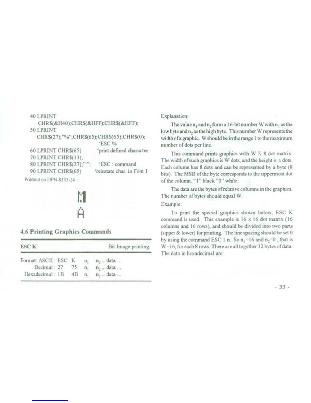
40 LPRINT
CHRS(&H40)
;CHR$(&HFF)
;CHRS(&HFF)
;
50 LPRINT
CHR$(27)
;"%
;CHR$(65)
;CHR$(65)
;CHRS(0)
;
`ESC %
60 LPRINT CHRS(65)
~
'print defined character
70 LPRINT CHR$(13)
;
80 LPRINT CHR$(27)
;" :";'FSC:command
90 LPRINT CHR$(65)
~
'reinstate
c
har
. inFont 1
Printout on DPN-83 33-2a
ri
H
4
.6 Printing Graphics Commands
ESC K
~
Bit Image printing
Explanation
:
The value ntand n
; form a 16-bit number W with n
t
as the
low byte and n, asthe high byte, This number W represents the
widthofagraphic
. Wshouldbeintherangeltothemaximum
number of dots per line
.
This command prints graphics with W X 8 dot matrix
.
The width of such graphics is W dots, and the height is
L
dots
.
Each column has 8 dots and can be represented by a byte (8
bits)
. The MSB ofthe byte corresponds to the uppermost dot
ofthe column
. "1" black "0" while
.
The data are the bytes of relative columns in the graphics
.
The number of bytes should equal W
.
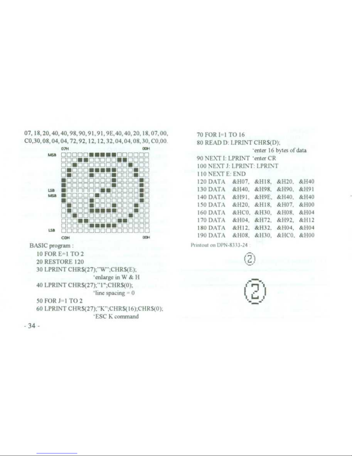
Example
:
To print the special graphics shown below, ESC K
command is used
. This example is 16 x 16 dot matrix (16
columns and 16 rows), and should be
divided into two parts
(upper & lower) for printing
. The line spacing shouldbeset 0
by using the command ESC 1 n
. So nt-16 and n,° 0 ,that is
\1'=16
. for each 8 rows
. There are all together 3 2 bytes of data
.
The data in hexadecimal are
:
-33
-
Format
: ASCII:ESC
K
ntn2. . .
data
. .
Decimal:27
75 ntn2. . .
data
. . .
Hexadecimal:1 B
4B
ntn,
. . .
data
. .
.
Page 42
-34
-
BASIC program
10 FOR E=1 TO 2
20 RESTORE 120
30 LPRINT CHR$(27)
;"W"
;CHR$(E),
'enlarge in W & H
40 LPRINT CHR$(27)
;" 1 "
;CHRS(0)
;
'line spacing = 0
50 FOR J=1 TO 2
60 LPRINT CHR$(27)
;"K" ;CIIRS(16)
;CIIR$(0),
'ESC K command
Primom on DPN-8333-24
r?7
07,
18, 20, 40, 40, 98, 90, 91, 91, 9E,40,40, 20, 18, 07, 00,
70 FOR 1=1 TO 16
C0,30,08,04,04,72,92,12,12,32,04,04,08,30,
CO,00
.
80 READ D
: LPRINT CHRS(D)
;
07H
~
a
1l
'erster 16 bv_ tes of data
heb
nnnnnN~~∎∎nnnnnn
nnn~~nnnnn~~nnnn
nn
.nnnnnnnnn•nnn
o•nnn
.
• . •
•o
nL•nn
n
•n
nn
.nnnunOO•nn
∎nnnnnnnn•nnnnZE
90 NENT I
: LPRINT 'enter CR
100 NE\T J
: LPRINT : LPRINT
110 NEXT E
: END
120 DATA
&H07,
&H18,
&H20,
&H40
∎nnnnnnnn•nnnnZZ
Lsa
∎nnnnnn~~onaao
•n
130 DATA
&H40,
&H98,
&H90,
&H91
.esa
∎nnnn3ZnnnnnnnZ2
140 DATA
&H91, &H9E,
&H40.&H40
∎nnnnUnnnnnnnDUn
n~nnn~nnn
.nnLIUnn
150 DATA
&H20,
&H18,
&H07,
&H00
o•onn•..
.
.onn•oo
160 DATA
&HCO,
&H30,
&H08,
&H04
nn~OOOOOOnnn•nnn
ooo
•
•a
nnnn
••n
noo
170 DATA
&H04,
&H72, &H92,
&H12
nnnnn
. .
.UUnnnnnn
180 DATA
&1112,
&H32, &H04,
&l104
W
nnnnnnnnnnnnnnnn
COH
~
oa
.+
190 DATA
&1108,
&H30,
&HCO,
&H00
Page 43
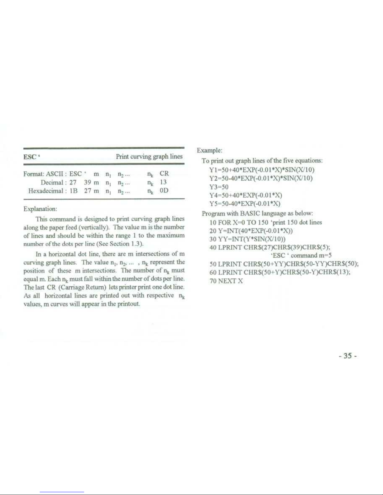
Explanation
:
This command is designed to print curving graph lines
along the paper feed (vertically)
. The value m is the number
of lines and should be within the range 1 to the maximum
number ofthe dots per line (See Section
1
.3)
.
In a horizontal dot line, there are m intersections of m
curving graph lines
. The value n
t
, n2, . .
. , n k represent the
position of these m intersections
. The number of n
k
must
equal m
. Each n k
must fall within the number of dots per line
.
The last CR (Carriage Retum) lets printer print one dot line
.
As all horizontal lines are printed out with respective n
k
values, m curves will appear in the printout
.
Example
:
To print out graph lines ofthe five equations
:
Y 1=50+40*EXP(-0
.01 *X)*SIN(X/10)
Y2=50-40*EXP(-O
.0 1*X~*SIN(X 10)
Y3=50
Y4=50+40*EXP(-0
.01 *X)
Y5=50-40*EXP(-0
.01 *X)
Program with BASIC language as below
:
10 FOR X=0 TO 150 `print 150 dot lins
20 Y=INT(40*EXP(-0
.01*X))
30 YY=INT(Y*SIN(X/10))
40 LPRINT CHR$(27)CHRS(39)CHR$(5)
;
`ESC`command m=5
50 LPRINT CHRS(50+YY)CHR$(50-YY)CHR$(50)
;
60 LPRINT CHR$(50+Y)CHR$(50-Y)CHR$(13)
;
70 NEXT X
ESC
`
Print curving graph lines
Format
: ASCII
: ESC ` m
n, n 2
. . .
nkCR
Decimal:27
39 m
n,
n2'
. '
nk13
Hexadecimal:1B
27 m
n n 2
. . .
nkOD
Page 44

4.7Initialization Command
ESC @
~
Initialize printer
Format
: ASCII:ESC @
Decimal
:27
64
Hexadecimal
: IB
40
Explanation
:
Reset printer to
:
•
~
clear print buffer
•
~
restore default values
•
~
select Font 1
•
~
de-select user-defined characters
4
.8 Data Control Commands
CR
~
Carriage Return
Format
: ASCII:CR
Decimal:13
Hexadecimal
: OD
Page 45

Explanation
:
~
Explanation
:
When a Carriage Return is sent to the printer, any data in
~
The previous character in the buffer is deleted unless that
the buffer is printed and paper is fed one line
.
~
character has already been printed
. This command will not
remove control codes
.
CAN
~
Cancel line
NUL
~
Null
Format
: ASCII
:
CAN
Decimal:24
~
Format
: ASCII:NUL
Hexadecimal:18
~
Decimal
: 0
Hexadecimal:00
Explanation
:
This commandcancelsalltextintheprintbufferpreceding
~
Explanation
:
this code back to the previous Carriage Retum
. It does not~NUL is used as the final code in some commands such as
cancel any control code sequences issued in that line
.
~
ESC B, ESC D, ESC % and ESC'
.
NUL command is ignored by printer when used alone
.
DEL
~
Delete character
Format
: ASCII:DEL
Decimal
:
127
Hexadecimal:7F
Page 46

ESC
"
Forthat
: ASCII:ESC
"~n
Decimal
: 27
34 n
Hexadecimal:1 B
22
n
Tum Hexadecimal Dump printing on/off
Explanation
:
Hexadecimal Dump print mode is tumed on if n=1, and
tumed off if n=0
. If you execute programs or list program in
Hexadecimal Dump print mode, all data sent from the host
computer will be printed out in hexadecimal
.
Example
:
W henthe following 4 data are sent from the host computer
after the command ESC
"
.
10 LPRINT CHR$(27)
;CHR$(34) ;CHR$(1)
;
20 LPRINT CHR$(0)
;CHR$(27)
;"A'
;CHR$(24)
;
The printout reads
:
00 IB 41 18
Printing in the Hexadecimal Dump mode is performed
only when the printer is in the line buffer-full state
.
Page 47

Chapter5.
Printing Examples
Example Programs below illList rate
BASIC
programs willen
for the DPN-8333 printer with different interfaces
5
.1 Parallel Port Printer
Example 1 DPN-8333
-24-PAR
printer is connected with the
parallel port of PC BASIC Program for printing a quoatation
:
10 'Print example för PARALLEL
port
printer
20 WIDTH "LPTI
:",255
30 ESC$=CHR$(27)
: TAB$=CHR$(9)
40 LPRINT
ESCS
;"D"
;CHRS(10)CHR$(15)CHR$(21)CI IR$(0)
:
50 LPRINT ESC$
:"W"
:CHR$(2),
60 LPRINT" "
;ESC$
;"-"
;CI1R$(1)
;
70 LPRINT "QUOTATION"
;ESC$,"-",CHR$(0)
80 LPRINT ESC$
;"W"
;CIIR$(1),
90 1-PRINT " "
100 LPRINT "PRODUCT UNIT PRICE"
110 LPRINT "CODE
~
(USD)
"
120 READ D$
: LPRINT D$
:
130 FOR J=1 TO 3
140 READ D$
: LPRINT TAB$
:D$
:
150 NEXT J
: LPRINT
160 GOSUB 240
170 FOR I=1 T0 7
180 READ D$
: LPRINT D$
:
190 FOR J=1 TO 3
200 READ D$
: LPRINT TA13$,D$
;
210 NE
:XT J
: LPRINT
220 NEXT 1 : GOSUB 240
230 LPRINT
: LPRINT
: END
240 FOR 1=1 TO 24
250 LPRINT
"-"
260 NETT 1
: LPRINT
270 RETURN
280 DATA"
~
1-50","50
+"
290 DATA "PW2302" "120","115","111
"
300 DATA "PW2101"
"R1"
310 DATA "PW I OI""64" "63" "61"
320 DATA 9W1
02","75","72","70"
330 DATA 9W21 1
"
~
"51"
340 DATA "PW212"
"17","16","
15"
350 DATA "PW301","9_5
~
1"
Page 48
-40-
-----------------------PW/
02
120 115
111
PW-'1O1::c•_t4
: 1
PW1ÜJ1~64~63
~
r1
FIM
1E+
~
-
.~7
0
Frol?'
11
~
5~
~
51
='t•121 Z~17~1
c
•
~
15
z14
-i_i 1
~
-
.5~'?
.
------------------------
5
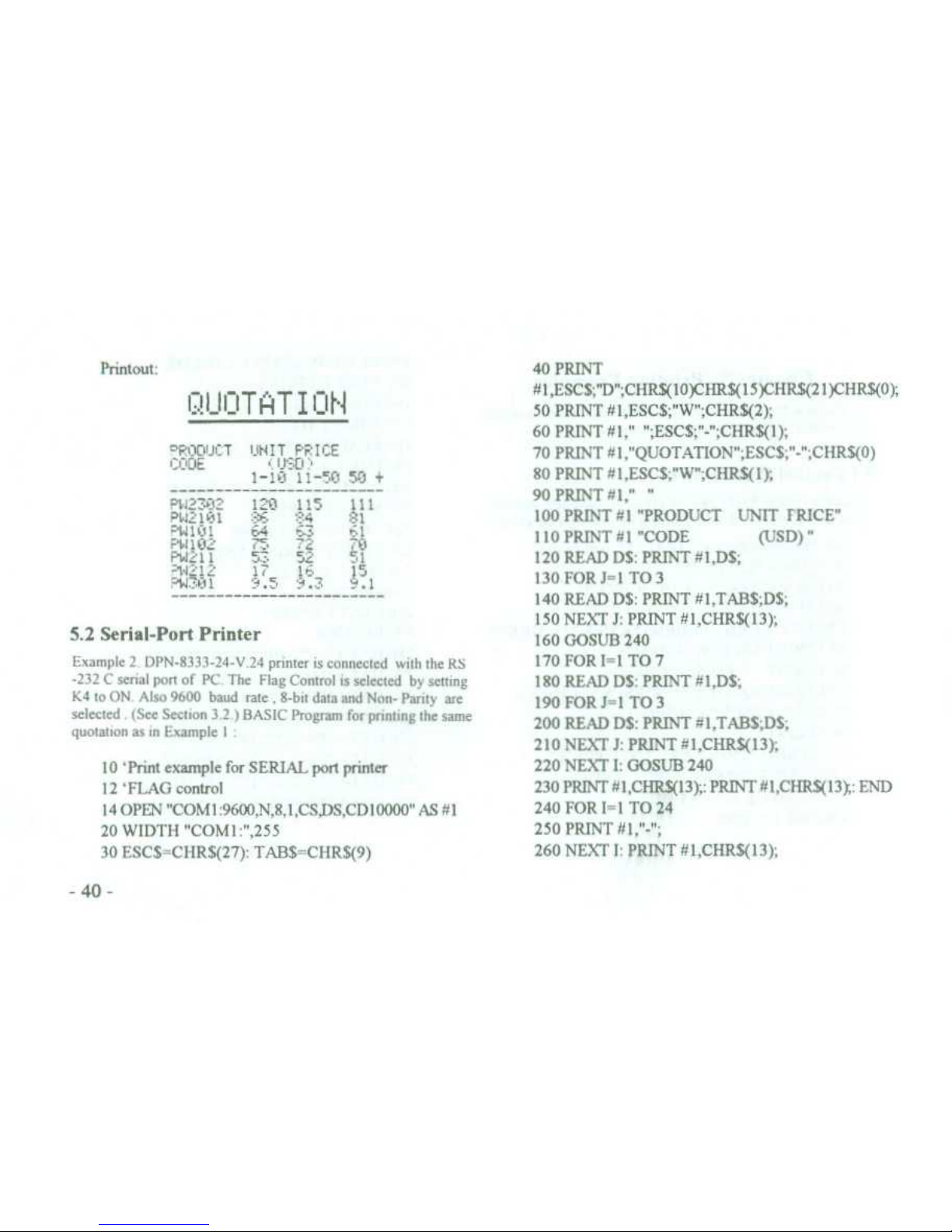
.2 Serial-Port Printer
Example 2
. DPN-8333-24-V
.24 printer is connected with the RS
-232 C serial port of PC The Flag Control is selected by setting
K4 to ON
. Also 9600 band rate
,
8-bit data and Non- Parity are
selected.(See Section3.2
.)
BASIC Program for printing the same
quotation as in Example 1
:
90 PRINT # 1,"
'-
100 PRINT #1 "PRODUCT
UNIT FRICE"
110 PRINT # 1 "CODE
~
(USD)
"
120 READ D$
: PRINT #1,D$
;
130 FOR J=1 TO 3
140 READ D$
: PRINT # 1,TAB$
;D$
;
150 NEXT J
: PRINT #1,CHRS(13)
;
160 GOSUB 240
170 FOR I=1 TO 7
180 READ D$
: PRINT #1,D$
;
190 FOR J=1 TO 3
200 READ D$
: PRINT #1,TAB$
;D$
;
210 NEXT J
: PRINT #I,CHR$(13)
;
220 NEXT 1
: GOSUB 240
230 PRINT#1,CHR$(13);: PRINT #1,CHR$(13y,
: END
240 FOR I=1 TO 24
250 PRINT
#1,"-"
;
260 NEXT 1
: PRINT #1,CHR$(13)
;
Printout
:
Ql li iTAT I i iN
40 PRINT
#1,ESC$
;"D'
;CHR$(10)CHR$(15)CHRS(21)CHRS(0)
;
50 PRINT #1,ESC$
;"W" ;CHR$(2)
;
eFOD3CT
JHIT F'F'ICE
CODE
~
U'33
)
1-Lt I1-50 50 +
60 PRINT #1," "
;ESC$
;"=
;CHRS(l)
;
70 PRINT # 1,"QUOTATION"
;ESC$
;"-'
;CHRS(0)
80 PRINT # 1,ESC$
;"W'
;CHR$(1)
;
10 'Print example for SERIAL port printer
12 'FLAG control
14 OPEN "COM 1
:9600,N,8,1,CS,DS,CD 10000" AS # 1
20 WIDTH "COMI
:",255
30 ESC$=CHR$(27)
: TAB$=CHR$(9)
Page 49

270 RETURN
280 DATA"
","1-10","I1-50","50
+"
290 DATA "PW2302" "120" "115" "111
"
300 DATA 7W2101"
"81"
310 DATA "PW
101","64","63","61"
320 DATA "PW 102" "75" "72" "70"
330 DATA "PW21 1
","53","52","51"
340 DATA "PW212" "17"
T',"~15"
350 DATA "PW301
","9
.5","9
.3","9
.1"
The printout of this program is same as Example 1
.
Example 3
. DPN-8333-24-V 24 printer is connected with the
RS-232C serial port on P C
. The XON / XOFF protocol is
selected by setting K4 to OFF
(
sec DIP switch setting in
section3.2).The other parameters are same as the example
above . BASIC program for testing XON / XOFF function
10 'Test XON/XOFF program
15 OPEN"COM I
:9600,N,8, l,CSO,DSO,CDO" AS # 1
20 WIDTH"COMI
:",255
30 ON COM(1) GOSUB 130
40 COM(1) ON
: XON=&H11
: XOFF=&H13
45 X$=CHR$(XON)
50 FOR J=1 TO 5
60 IF X$=CHR$(XOFF) THEN 60
70 PRINT 41,CFIRS(I3)
;CHR$(J),".";
Run program
. The printer prints 5 blocks of ASCII
characterset
. The contents ofthese 5 blocks must
be
the same
.
Ifnot, XON/XOFF function ofthe printer is wrong
. The DIP
switch setting must then be
re-checked
.
80 FOR 1=32 TO 255
90 PRINT #I,CHR$(1)
;
100 IF X$=CIIR$(XOFF) THEN
100
110 NEXT 1
120 NEXT J
: END
130 X$=INPUT$(1,#I)
140 RETURN
Page 50

Chapter6. Operating Note
1
.
Do not dismantle printer head
.
2
. Do not leave power on when not in use for a long period
.
3
. Switch off if printer works abnormally
.
4
. Power supply must match requirement
.
See Section 2
.5
.
5
. Do not lubricate the printer head
.
6
. Fluff and dust from paper are harmfitl to
printer head
.
Check and clear the head when replacing paper roll
.
7
. When replacing ribbon, do not press the
cassette too
heavily
. Otherwise the plastic wheel
on the head may
be damaged
.
8
. Keep the main circuit board clean
.
9
. Do not remove the IC chips in the main board
.
10
. Never use ribbon oil
. It may damage printer head
.
11
.
Do not tear the paper when the printer is printing or feeding paper
.
Page 51

Appendix A
. DIP Switch
DIP switch settings
:
Parity Setting
Handshaking Setting
DIP SWITCH
ö000DD
000000
000000
10 0
0U00
HANDSHAKING
FLAG
XON/XOFF
DIP SWITCH
PARITY
önoou∎
000000
8-NON
0000!>O
00000∎
8-ODD
000005
0000Ua
8-EVEN
ö00000
0000
ZZ
7-EVEN
There is a seven-section DIP switch inside the case near the
~
Baud Rate
Setting
connector This is used to set the parameters of the serial port
of DPN-833/8233/8333--V 24 Three switches of the DIP
switch are used to set the Baud Rate One sets Handshaking
DIP SWITCH
EPS
in
150
The remaining two switches set 8 bits or 7 bits each character
uooo
000000
as well as Parity check
ÖZZOOO
300
∎o000n
The DIP switch was set ex-factory as
:
i
11a1
:1
Ex-factory Switch Setting
:
~
D00000
00000
ON
∎~OCOC
1200
ööiöö~
2400
0
1~2 3 4 5 6
00000 J
∎L
;
TUU
4800
100000
i.e.
Baud Rate 9600 bps, Handshaking X-ON/X-OFF
~
nu0000
9600
protocol, character 8 kits, and Parity Check tion-Parity
.
öa000U
∎uUDOLI
19200
Page 52

Appendix B
. Character Code Tables
There are two character code tables or sets in the printer
.
Code Range from 20H (Hexadecimal)to FFH (Hexadecimal)
.
Code 0011 to 1 FH are control codes (See Appendix C
.)
.
ESC 6 command is used to select Font 1 (Character code
table 1), and ESC 7 to select Font 2 (Character code
table 2)
.
Font 1
:
0 1 2 3 4 5 6 7 8 9 ABC D E F
2
! # $ % & , ( ) * +
. - . i
3
9 1 2 3 4 5 6 7 8 9
;<_>?
4
A A 9 C 0 E F 6 H 1 J K L M N 0
5
P 9 R S T U V W X Y Z C\ 1 _
6
`
a b c d e f 9 h i± k l m n o
7
P
•a
r s t u v a x y t
~
i
$
9ü
~
3ädiS
~
e?14i äd
9
A
s# ä i~~ü
~
9 6 VCE Y h f
C
l r F- i
~
IIeG-` x R=
v l
D
L~,r ¢ E
F
rt$
1
J r/∎
I
1'
E
aßrA7
.öK
~eaö
•r
oEn
F
=±i_< pJ-
.o
.p
~
lns
.
Page 53

Font 2
:
012 3
4 5 6 7
8 9 ABC D E F
23-==or,
;,tjtnt5fhnas
x
.ii
i1
~
.2t9
S
i
G
l E
h 137
'1 ~L
V 0 7 4 2 9
6 i
7
f x
x b
a 3
F A E
:Y 3
7
t•I~rn11
4W
11b113lr1A6
1
5
$
YC ITi
nv~
P?W
rpei'PQ
9
anrZt1Fa5
'~*c< >x
A
1 X Hu8 c
:J
a f l a':
•
:
c
rL
.J-1xx
1
1i\rLJ1-i
D
~,
r'~LTE4F
I%,-'
•<
>
E
1.".r1J93
F
.
. .
~
c
~v
A
9
nx
t y'
0
3
0 2
i
Page 54

Appendix C
. Printing Command Codes
Decimal Hex.Symbol Format
NUL
Function
Ending signal
~
Page
37
0
00
9
09
HT
Horizontal tab
~
24
10
OA
LF
Line Fee
~
20
11
OB
VT
Vertical tab
~
23
12
OC
FF
Form Feed
~
21
13
OD
CR
Carriage Retum
~
36
14
OE
SO
Double-width print
~
30
20
14
DC4
Cancel SO command
~
30
24
18
CAN
Delete line
~
37
27 34
1 B 22
ESC
" n
Hexadecimal Dump print
~
27 37
1B25
ESC % m, n,.. .
NUL
Replace with user-defined characters
~
32
27 38 1B 26
ESC & m n,
. .
. n
b
Define user-defined character
~
31
2739 1B27
ESC`mn,
. ..nk
CR
Print curving graph lines
~
35
27 43
1B 2B
ESC + n
Overscope
~
29
2745
1B2D
ESC -n
Underline
~
28
27 49
1B 31
ESC 1 n
Set line spacing
~
20
27 54
1B36
ESC 6
Select Font 1
~
29
27 55
1B37
ESC 7
Select Font 2
~
29
27 58
1B 3A
ESC
Reinstate character in ROM
~
32
Page 55
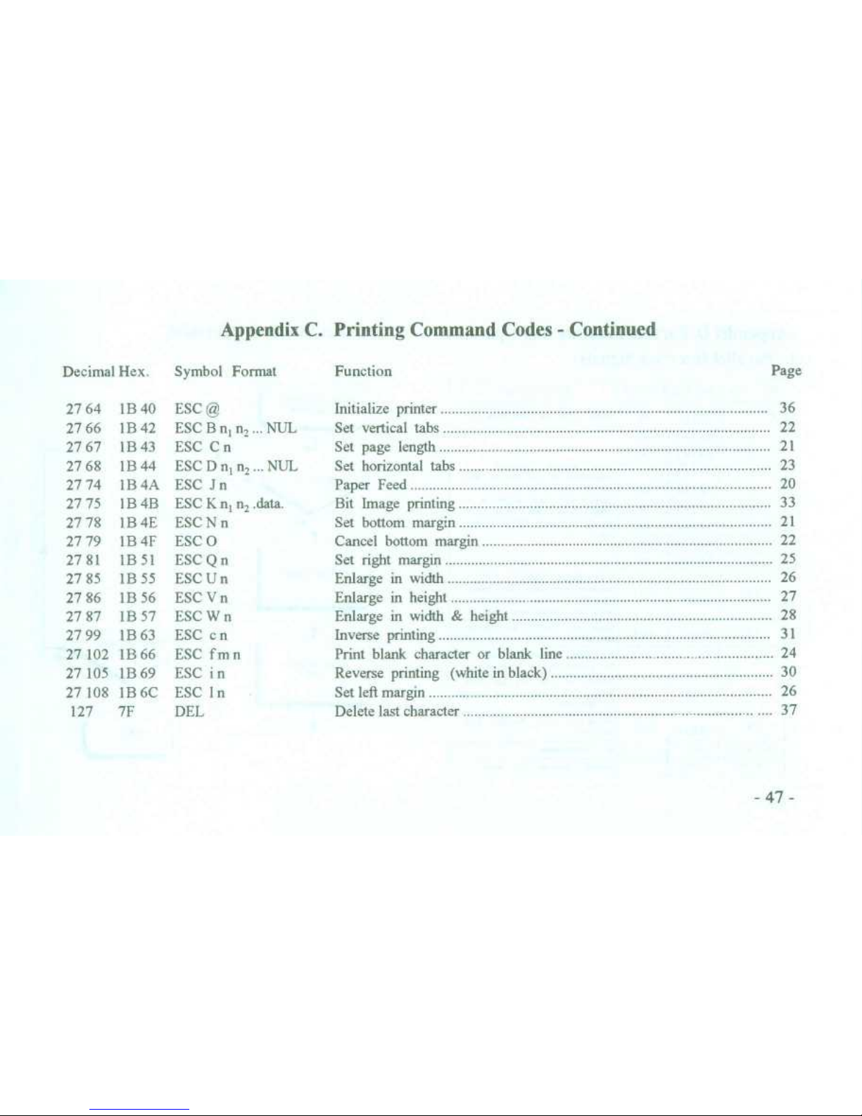
Appendix C. Printing Command Codes-Continued
Decimal Hex
.
Symbol Format
ESC @
Function
~
Page
27 64
1 B 40
Initialize printer
~
36
27 66
1 B 42
ESC B n, n,
. . .
NUL
Set vertical tabs
~
22
2767
1B 43
ESC C n
Set page length
~
21
27 68
1B 44
ESC D n, n2. ..NUL
Set horizontal tabs
~
23
27 74
1 B 4A
ESC J n
Paper Feed
~
20
27 75
1B 4B
ESC K n, n2.data
.
Bit Image printing
~
33
27 78 1B 4E
ESC N n
Set bottom
margin
~
21
27 79
1B 4F
ESC 0
Cancel bottom margin
~
22
2781
1B51
ESCQn
Set right margin
~
25
27 85 1B 55
ESC U n
Erdarge in width
~
26
27 86
1B 56
ESC V n
Enlarge in height
~
27
27 87 1B 57
ESC W n
Enlarge in width & height
~
28
27 99
1 B 63
ESC c n
Inverse printing
~
31
27 102
1B66
ESC fin n
Print blank character or blank line
~
24
27 105
1B69
ESC i n
Reverse printing (white in black)
~
30
27 108
1 B 6C
ESC I n
Set left margin
~
26
127
7F
DEL
Delete last character
~
37
Page 56

Appendix D
. Parallel Interface and Operation
1.Parallel Interface Signals
-48-
2
. Parallel Interface Operation
7
PARALLEL PORT
OPERATION
TRANSMIT DATA
SEND SIGNAL
STB
END
ßn No
Signal
In/Out
Description
t
STB
IN
Sbobe
pole
.Inread lote
in
2
DATA1
IN
3
DATA2
IN
4
DATA3
IN
Theea
~i~
1
.'
reprea
.m
inl«meuonofIhn
1ettoBth
bilo of
perellel
date
reepedively.Each
.
.~I
~
eI
5
DATA4
IN
8
DATAS
IN
'
i-
HIGH'
IeoN
when
date
logcel-1-end-LOW
when
logicel~-o-
DATA6
IN
8
DATA?
IN
8
DATA8
IN
1 0
A K
O U
Acknnwledge
pose~-
LOW'
indcete
. the' date h.. been
r
eived ond thel dw printer ie
ready to accept
11001
date
.
11
BUSY
OUT
Sigml
Ki-HIGH-to indcete
the pirl«
00!0101
000
pt
date
.
12
PE
A-HIGH-nignel inAcete0 lhet
the printer n «1
of pep«
.
13 SEL
OUT
PJI-apto+5V through 3
.35
red
.tor, to indcete the printek
in~ON -LINE
.
15
ERROR
OUT
-~to
.5V
Jvough3.35Pullup
,eeietor
.
14 16 17
NC
No~connocti«t
18
.25
GND
Grocod,
Logkai-0"
level
.
Page 57

Appendix E
. Serial Interface and Operation
1
. Serial Interface Signals
2
. Serial Interface Operation
SELECT
BAUD PATE
SELECt PABITY
-49-
PinNo.
Signal
Source
Description
2
TxD
Host
Printer receives data from
host computer
3
RxD
Printer
Printer trasmits data when
uses the handshaking of
X-ON/X-OFF
5
CTS
Printer
Signal sets "MARK" state to
indicate the printer is BUSY
and can not accept data,
and "SPACE" state to
indicate the printer is ready
and can accept data
.
6 DSR
Printer
Signal sets "SPACE" 1o
indicate the printer is
ON-LINE
7
GND
Signal Ground
8
DCD
Printer
Same as CTS
Page 58
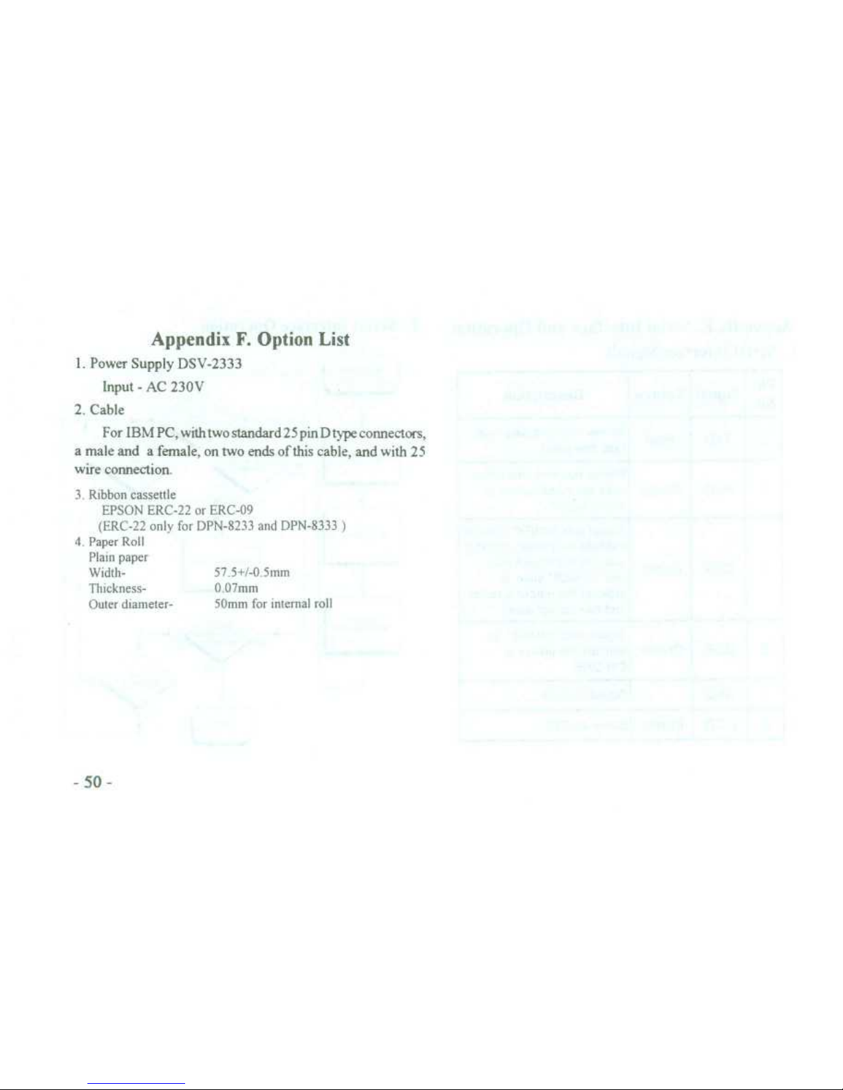
AppendixF. Option List
1
. Power Supply DSV-2333
Input-AC 230V
2
. Cable
For IBM PC, withtwo standard 25 pin D type connectors,
a male and a female, on two ends of this cable, and with 25
wire connection
.
3
. Ribbon cassettle
EPSON ERC-22 or ERC-09
(ERC-22 only for DPN-8233 and DPN-8333
)
4
. Paper Roll
Plain paper
Width-
~
57
.5+/-0 5mm
Thickness-
~
0
.07mm
Outer diameter-~50mm for internal roll
Page 59
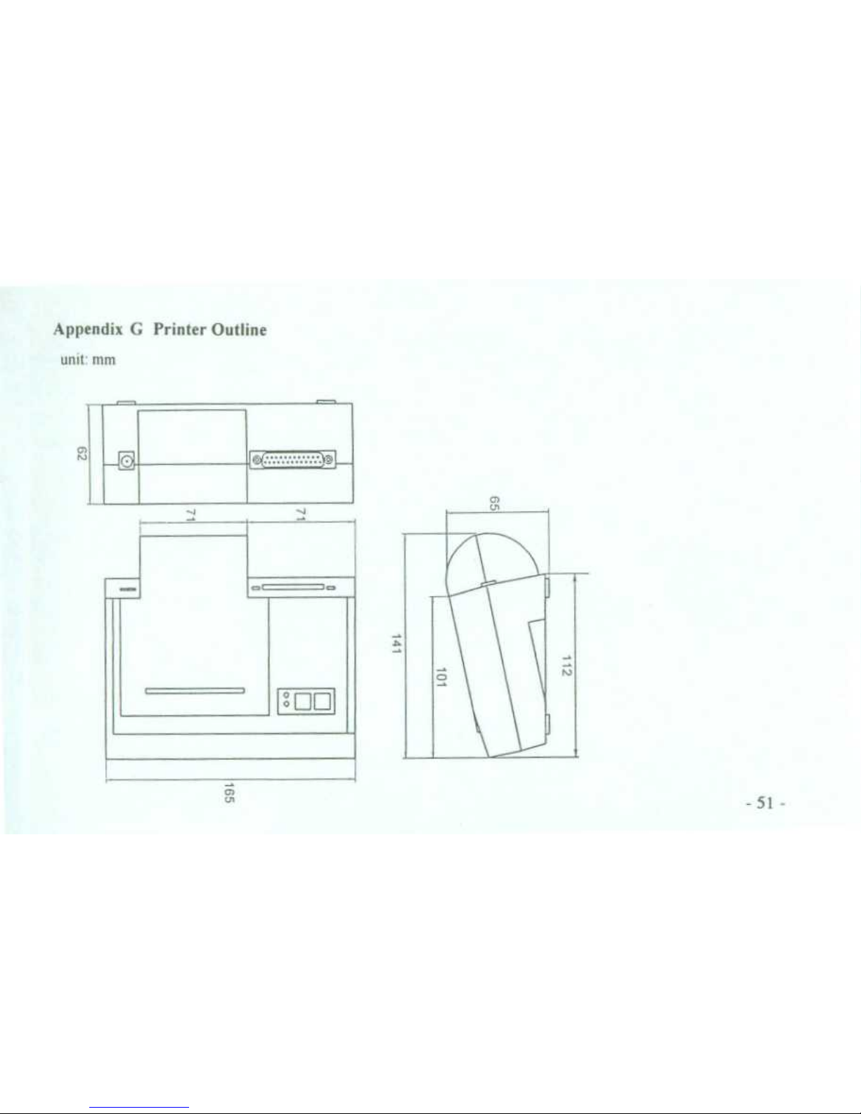
Appendix G Printer Outline
unit
: mm
N
1
0
[In
Page 60

Page 61

,,
Page 62

es
∎
∎
mmr
~
ti∎
∎ Z '
Z
~
9p
1
~
r i '
∎ ∎
∎
~
- - ∎∎
Page 63

Page 64

 Loading...