

Page 1
Operation
Manual
Model #’s
525, 550, 600,
700 and
900et
This manual will familiarize you with the features and operation of
your new WatchDog Weather Station. Please read this manual
thoroughly before using your instrument. For customer support, or to
place an order, call Spectrum Technologies, Inc. at (800)248-8873 or
(815) 436-4440 between 7:30 am and 5:30 p.m. CST, FAX at (815)
436-4460, or E-Mail at info@specmeters.com.
Spectrum Technologies, Inc
23839 W Andrew Rd.
Plainfield, IL 60544
CONTENTS
General Overview 2
Internal Sensors 2
External Sensors 3
Anemometer Setup 3-4
LCD Display Panel 4-5
Connecting to Computer 5-6
Weather Bulletin 6
Mounting the Weather Station 7
SpecWare Software 7
Battery Replacement 8
Trouble Shooting 8
Service and Support 9
Warranty 9
Page 2

2
General Overview
This manual describes how to use your WatchDog Weather Station
and how to keep it working accurately for many years. Read this
manual thoroughly in order to make effective use of your weather
station.
The WatchDog Weather Station will allow you to record and monitor
real-time local weather information at remote sites. Your weather
station can also be connected to as many as 4 additional sensors via
the external sensor ports. Through the software, simply configure the
weather station to record the appropriate sensors.
Download the accumulated data at your convenience using the
powerful SpecWare software. SpecWare will present the data in
graphical and tabular form. Use the software to calculate growing
degree days and chill hours, leaf wetness, temperature and RH hours,
or view daily, monthly, and yearly reports. Optional disease and
insect models aid the user with Integrated Pest Management decisions.
Evapotranspiration calculations to aid in irrigation scheduling are also
available with the 900ET station.
Sensor Measurement Range Accuracy
Wind Speed 0-175 mph ±5%
Wind Direction 2o increments ±7o
Temperature
(Wind Chill)
-30° to 100°C
-22° to 212° F
-40° to 104°C
-40° to 40° F
±0.7°C
±1°F
±4
o
F
±2
o
C
Relative Humidity*
(Dew Point)
20% to 100%
@5° to 50° C
-99
o
F to 140oF
-73
o
FC to 60oC
±3%
±4
o
F
±2
o
C
Rainfall 0.01” (0.25cm)
resolution
±2%
Solar Radiation
**
1-1250 W/m2 ±5%
•
RH and Dew point available on model 550, 700 and
900ET stations only.
**
Included with 900ET station. An option on model
525, 550, 600 and 700 stations
Each channel has a data capacity of 3100 measurements. Therefore, a
30 minute measurement interval will allow the datalogger to record
for 64 days.
internal Sensors
Page 3
3
WatchDog Weather Stations have external ports available for external
sensor input (Models 525, 550, 600 and 700 have 4, Model 900ET has 3).
The following table lists the available optional sensors. All sensors include
a 6-foot cable with pin-type connector.
To connect an external sensor to the logger, plug the sensor cable into the
logger port that has been programmed for that particular sensor. If the
sensor is not connected, the message “sensor error” will appear on the LCD
display for the respective logger port until the sensor is connected.
External Sensors
Item #
Sensor
Description
Measurement
Range
Max #
per
station
Accuracy
3666 Leaf Wetness 0(Dry) - 15(Wet) 2 N/A
3667 (6ft)
3667-20 (20ft)
External (Soil)
Temperature
-30° to 100°C
-22° to 212° F
3 ±0.7°C
±1°F
3670 Silicon
Pyranometer
1-1250 W/m2 1 ±5%
3668 Quantum Light 0-2500 µmol/m2/s 2 ±5%
3669,
3669LT
Soil Moisture
Transducer
0-100 kPa (R-type)
0-40 kPa (LT-type)
2 ±2%
6450WD (6ft)
6450WD20
Watermark Soil
Moisture Sensor
0-200 kPa (WM-type)
3 N/A
3664 20 ft. Extension
Sensor Cable
N/A N/A N/A
6451 Irrigation Sensor Switches at 5 psi 1 ±1 psi
6471 Barometric
Pressure Sensor
26 - 32 in Hg
660 - 810 mm Hg
1 ±0.05”
±1.3 mm
3673
3674
Input Cable for
User Supplied
Sensor
0 - 2.5V
4 - 20mA
3 N/A
Program each port to a specific sensor through the Launch Options Screen in
SpecWare software.
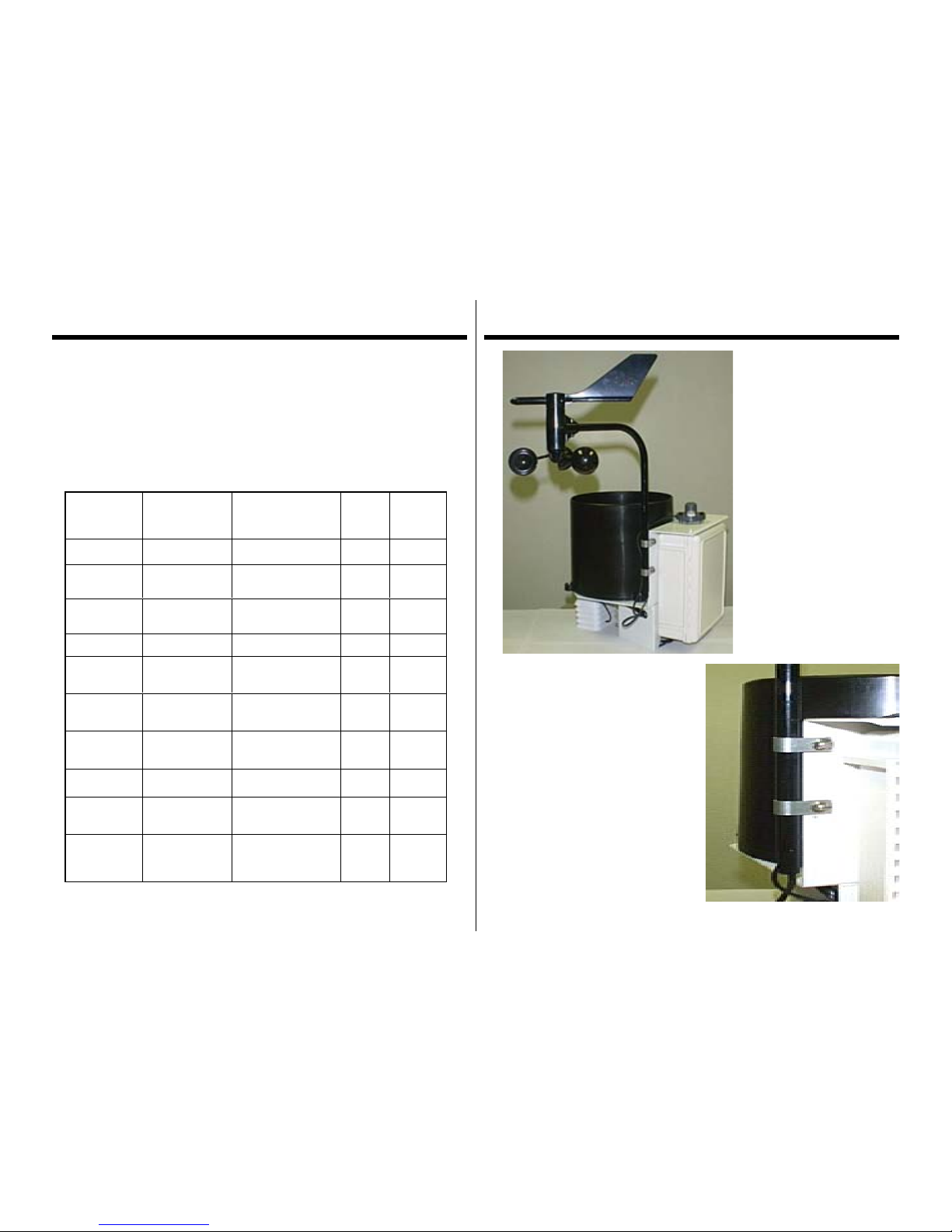
Anemometer setup
Apart from the
anemometer, the
WatchDog Weather Station
comes fully assembled and
ready to mount. The
anemometer arm is
attached to the enclosure
back plate with two
clamps. After positioning
the arm, the screws should
be tightened to secure it in
place.
Push the wind cups onto the bottom
of the shaft flush with the bottom of
the assembly and tighten the set
screw. When released, the cups
should drop slightly. If the cups do
not spin freely, loosen the set screw
and lower the cups slightly. The gap
between cup hub and assembly
should be about 1/16 inch.
Push the wind vane onto the top of
the shaft and calibrate (see next page
for calibration procedure).
Anemometer clamped to back plate
Page 4

4
Calibrating the Wind Vane
When the weather station is initially placed in the field or moved, the
wind direction must be calibrated. The following procedure will
allow you to establish accurate wind direction readings.
1. Turn on the display by pressing the Display button and press the
arrow keys until the wind information is displayed.
2. Rotate the wind vane until it is pointing north.
3. Press and hold the reset button until you hear a steady stream of
beeps. The anemometer is now calibrated.
If you are using external sensors, the sensor wires should be run
through the bottom of the enclosure by slotting the wires inside the
notched plastic cap. Plug the sensor cables into the logger port that
has been programmed to read that sensor.
Refer to the SpecWare Software User’s Guide for more detailed
instructions on launching and sensor configuration.
Anemometer setup (cont.)
Important: Secure the external sensor wires to the mounting pole
with a plastic tie. This will ensure that the sensor wires do not
become disconnected while recording.
LCD Display Panel
The digital LCD screen displays on-site readings and calculated parameters such as evapotranspiration (900ET station), dewpoint
(900ET, 700 and 550 stations) and wind chill. The LCD display is
only active after the weather station is launched and is logging data.
View the LCD to confirm that the logger is working and to observe
current weather conditions. The screen will automatically go dormant
after 15 minutes. The display can then be turned on or off by pressing
the
Display
key.
Sensor readings are updated every 20 seconds. If “sensor error”
appears on the display, the external sensor is not connected properly
or is not functioning properly. Use the arrow keys to scroll forward or
backward through current readings. The scrolling function is temporarily suspended while readings are being updated.
When the station’s logger measurement capacity is reached, the LCD
will display “Memory full”. A full logger needs to be downloaded
and relaunched before it can collect more data.
Page 5

5
LCD Display Panel (cont.)
Sensor Information is displayed as follows:
Wind
Current speed and direction,
Maximum gust during last
interval
Rain
Total since logger was launched
and cumulative since reset
RH,
Air Temperature
Current value, Maximum and
minimum since midnight (time
stamp included with max and
min values)
Solar Radiation ,
WindChill, Dew Pt.
Current value
Evapotranspiration
(available on 900ET
station only)
Total from last 24 hour
period - updated every hour
External Sensors
(see pg. 5)
Current value
Hi-Lo/Reset Key
The
Hi-Lo/Reset
is used for viewing time-stamped maximum and minimum
values for air temperature and relative humidity, resetting the cumulative
rainfall and calibrating the wind direction. Before
using the Hi-Lo/Reset button , be sure the parameter of interest is displayed
on the console. Maximum and minimum values are automatically reset at
midnight
To reset the cumulative rainfall reading to zero, press and hold the Hi-Lo/
Reset
button until you hear a steady series of beeps.
To view maximum/minimum values for RH or air temperature, press and
release the Hi-Lo/Reset button.
Connecting to Computer
Remotely Located Stations
If you are using the WatchDog Data Shuttle (item # 3679) to interface
with your weather station, the weather station’s datalogger must be
launched by a PC before being installed in the field or if changes
(station name, measurement interval or external sensors) need to be
made in the logger configuration. Routine download/launch
operations can be carried out with a laptop computer or the Shuttle.
Refer to the SpecWare Software User’s Guide for complete
instructions on launching and downloading the WatchDog loggers.
When launching or downloading data, connect the station to a
computer using the data transmission cable. This cable is included
with the SpecWare software package. The data cable connects to an
available serial port on your personal computer and the port labeled
“computer” on the station.
For remotely located weather stations, the only time you must have
the WatchDog connected to the computer is during the launching and
downloading of the station.
If the computer will not connect with the station, you may need to
change the batteries or change the com port settings. Refer to the
Battery Replacement
section on page 15 for battery instructions.
Direct PC Connection
It is possible to connect you weather station directly to you computer.
A direct PC connection cable allows you to monitor the weather
station’s current weather conditions and perform launch and download
operations from an office PC.
With the 6 ft. cable, connect the serial pin to the port labeled
“computer” and the 9-pin female connector to the computer data port.
Page 6

6
Connecting to
Computer (cont.)
The 100 and 200 ft. cables have modular (telephone-type) connectors
on one end and a 9-pin female connector on the other. Plug the
modular connector into the port labeled “Aux” on the display console
and the 9-pin connector to the computer data port.
Short-Range Modem Pair
The weather station can be hardwired up to 4000 feet from a PC with
twisted-pair cable and a short-range modem pair. The cable is
connected to the weather station and computer in the same manner as
the 100 and 200 ft. direct PC connections.
Caution:
Extended lengths of electric cable such as the Direct PC
connection and cable connected to a short-range modem pair can
attract lightning. It is recommended that the cable be connected to a
surge protector (item # 3660SP). This provides upgraded protection
against voltage surges caused by nearby lightning strikes.
Weather Bulletin
Refer to the
SpecWare Software User’s Guide
for complete
instructions on accessing bulletin and launch/download functions.
When the station is hard-wired directly to the computer, it is
possible to see current weather conditions by clicking on the
Weather Station Monitor
icon on the SpecWare toolbar or
by clicking
Weather Station Real-Time Monitor
under the
Logger
menu. This will bring up a bulletin displaying the current weather
conditions. The weather station must be launched and running to send
weather data.
Refresh/Repeat Refresh
The user can view current weather conditions at the station by clicking
the
Refresh
button. The auto refresh feature is enabled and disabled
by clicking the Repeat Refresh button. If enabled, the weather
bulletin will be automatically refreshed every 5 minutes.
Reset Rain
Clicking this button resets the cumulative rainfall to zero.
Page 7

7
Mounting The station
The weather station should be located in an open, unobstructed, grassy
area to ensure accurate measurement of wind, rainfall, sunlight, and
evapotranspiration.
Mounting hardware is provided to attach the weather station to a 4” x
4” treated wooden post or to a mast/pole up to 1.25 inches in diameter.
The mounting pole should be securely anchored perpendicular to the
ground.
If you are using the mounting tripod (item # 3396TP), open it and
place it where the weather station is to be located. The tripod feet can
also serve as mounting brackets if the unit is located on a solid
surface. Slide the 3’ post through both center screw clamps, adjust the
height as desired and tighten the screws such that the post is
perpendicular to the ground. Finally, attach the weather station to the
post with the u-bolts.
Weather Station mounted
on tripod
SpecWare Software
To use the WatchDog Weather Station, SpecWare 6.0 software is
required. SpecWare software is an integral part of the WatchDog
logger family.
- Use SpecWare software to initially program or configure the
weather station for the specific external sensors being used.
- Use SpecWare software to launch the weather station to record
specified parameters at chosen measurement intervals. Interval
choices offered are 1, 10, 15, 30, 60, and 120 minutes.
- Use SpecWare software to read-out and save the logged data.
- Once the data has been downloaded to the computer, SpecWare
software offers a wide variety of Report options and Disease and
Insect Model options.
Refer to the SpecWare Software User’s Guide
for more detailed
instructions.
Page 8

8
Battery Replacement
Each WatchDog weather station is powered by four AA alkaline battery cells. The batteries have a life of 8 months continuous use. They
are user replaceable and can be purchased locally. The station must
be relaunched after the batteries are removed and/or replaced.
Note: The weather station parameters
can’t
be changed if the datalog-
ger is relaunched by the Data Shuttle.
To replace the battery:
1. Remove the thumbscrews on the upper cover of
the WatchDog (above the LCD).
2. Slide the batteries out of the battery holder.
3. Insert new AA cells.
4. Replace battery cover.
5. Tighten cover screw.
The weather station will beep when the last battery is inserted. This
confirms the datalogger is working. The LCD screen will not illuminate until the weather station has been launched.
Service and Support
The WatchDog Data Loggers are easy to use and reliable. Should you
have a problem, or have questions:
Who do I contact?
Contact the company you purchased the data logger from: Spectrum
Technologies, Inc. or an authorized Spectrum Dealer.
When Contacting Spectrum Technologies:
Please indicate that you need Technical Support.
Be prepared to:
1. Provide details on the hardware and software configuration of your
components including: manufacturer, model number, peripherals and
versions of the operating system.
2. Completely describe the problem. The more information you
provide, the faster and more accurately we will be able to respond.
Page 9

9
Commonly asked questions include:
Q. Why will station not connect with computer?
A. Station needs new batteries, or the com-port settings need to be
changed through SpecWare software. Refer to
SpecWare User’s
Guide for details.
Q. Why is logger displaying “sensor error”
A. The logger will display “sensor error” for the external sensors if i.)
another external sensor is connected to the port meant to record
rainfall or ii.) the sensor is not securely plugged into a channel
port.
Q. Why is logger displaying and/or logging bogus, or out-of-range,
readings?
A. External sensors may not be plugged into correct ports.
Q. LCD display will not function.
A. Station needs to be launched from a PC with
SpecWare 6.0 software
Q. My weather bulletin will not update.
A. Verify that the station has been launched and is
currently running.
Trouble Shooting
This product is warranted to be free from defects in material or
workmanship for 1 year from the date of purchase. During the
warranty period Spectrum will, at its option, either repair or replace
products that prove to be defective. This warranty is void if the
Spectrum products have been damaged by customer error or
negligence, or if there has been an unauthorized modification.
Returning Products to Spectrum
Before returning a failed unit, you must obtain a Returned Goods
Authorization (RGA) number from Spectrum. You must ship the
product(s), properly packaged against further damage, back to
Spectrum at your expense. Clearly mark the RGA number on the
outside of the package
. Spectrum is not responsible for any package
that is returned without a valid RGA number or for the loss of the
package by any shipping company.
Warranty
23839 W Andrew Rd
Plainfield, IL 60544
(800) 248-8873 or (815) 436-4440
FAX: (815) 436-4460
E-Mail: info@specmeters.com
www.specmeters.com
Technologies, Inc.
Spectrum
 Loading...