

Page 1
Retriever & Pup
Wireless Network
PRODUCT MANUAL
Items 3900, 3901, 3902, 3910, 3910S
3905, 3906, 3907, 3911, 3911S
1
Page 2

INTRODUCTION
Thank you for purchasing a WatchDog Retriever & Pups
Wireless Sensor Network.
The WatchDog Retriever & Pups Wireless Sensor Network is a
technologically advanced solution that provides growers the
ability to capture real-time, site-specific data in various
microclimates.
The Wireless Network consists of one Retriever and many
Pups. There are three types of Pups: Sensor Pups, Station
Pups, and Repeater Pups.
Each Sensor Pup within the network is compatible with a
diverse number of sensors and offers flexibility by allowing the
grower to monitor the sensor inputs they care about in the
locations they care about.
Station Pups are compatible with existing WatchDog 2000
Series Weather & Mini Stations and offer the ability to plug in
and transmit the full data set to the end receiver along with data
from other Sensor Pups across the growing environment.
Repeater Pups do not have sensor inputs. They can be used to
provide additional paths to extend the network.
All data acquired by the Pups is transmitted back to the
Retriever—the central point that collects, logs, and transmits the
data.
The communication options are cellular modem, Wi-Fi, direct
connection to PC, and USB flash drive. Communication options
allow for automatic upload of the data to a computer or the web
for further analysis.
Growers can monitor their crops on their computer or
smartphone and make real-time decisions that improve yield
and quality, conserve resources, and increase profits.
2
Page 3

TABLE OF CONTENTS
General Overview 4
External Ports 6
Getting Started
Setup 9
Configuration 10
Retriever/Pup Operation 18
Installation 20
Data Logging & Storage 24
Updating Firmware 25
Data Export 26
Accessories 30
Specifications 31
Power 32
My Network Library 33
Troubleshooting Guide 34
Regulatory Information 35
This manual will familiarize you with the features and operation
of your new WatchDog Retriever & Pups Wireless Network.
Please read this manual thoroughly before launching the units.
For customer support or to place an order, call Spectrum
Technologies, Inc. at 800-248-8873 or 815-436-4440,
FAX at 815-436-4460, or e-mail at info@specmeters.com.
8
www.specmeters.com
Spectrum Technologies, Inc.
3600 Thayer Court
Aurora, IL 60504
3
Page 4
GENERAL OVERVIEW
Wireless Mesh Network
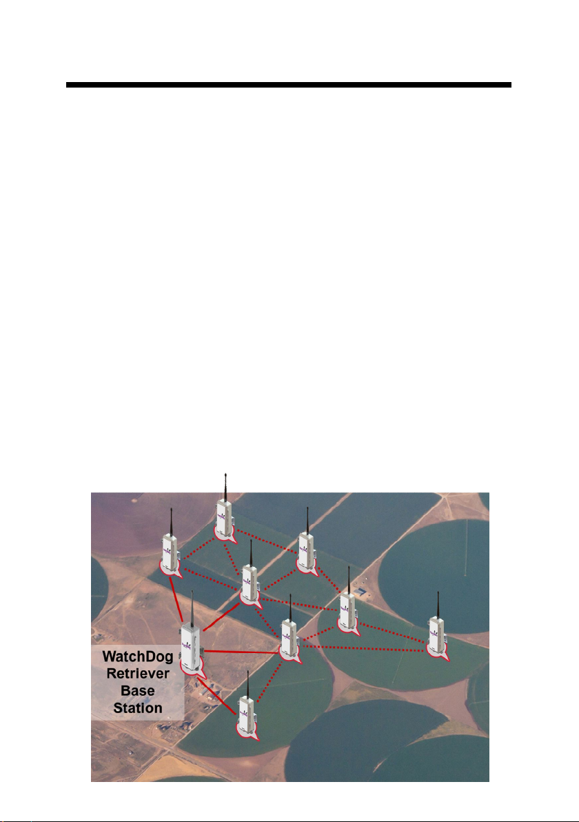
The Retriever & Pups wireless sensor network uses a mesh style
of communication, which allows any Pup within the network to
wirelessly route data from another Pup back to the Retriever.
The size of a network can vary by growing conditions,
topography, and user preference. The mesh network is
constrained to a maximum number of 16 Pups per network at a
distance of 2500 ft (about ½ mile or ¾ kilometer), or less
between Pups, with no more than four hops back to the Retriever
for the most remote Pups.
Pups have the ability to send their sensor data to the Retriever
within minutes of measurement. The data can be sent directly to
the Retriever, which logs the sensor data, or hopping via other
Pups within the mesh network. All Retriever and Pup units are
time synchronized. Because of this, the entire wireless network
can ‘go to sleep’ for periods of time to conserve battery life.
When the network ‘wakes up’, the Pups all communicate to the
Retriever and share any sensor data they have recorded while
the network was sleeping.
4
Page 5

Components
The mesh network is made up of one Retriever and a userdefined number of Pups. It may include Item #’s 3900, 3901,
3902, 3910, or 3910S using 900 MHz radios or 3905, 3906,
3907, 3911 or 3911S using 2.4 GHz radios.
Item Description
3910
Retriever
3910S
Retriever Solar
3900
Sensor Pup
3901
Station Pup
3902
Repeater
Pup
*Requires firmware: Weather Station ≥ v7.6 (2800 - v3.5), Mini Station ≥ v4.1
Receives all data from Pup network and
communicates the data via three options
-USB flash drive
-Direct to PC
-DataScout modem (sold separately)
Up to 4 sensor inputs, transmit data to Retriever
(direct or hopping via other Pups)
*Plug in a WatchDog 2000 Series Weather Station
or Mini Station and transmit all sensor data to Retriever (direct or hopping via other Pups)
No sensor inputs, serves as a hopping node to
help provide a path for the transmission signal
around obstacles
Your WatchDog Retriever & Pups package should contain the
following components:
Product Manual
Retriever and Pup units (labeled on enclosure & inside)
USB flash drive, preloaded with Retriever and Pup Launch
Utility software
USB to 3.5mm Stereo Plug Cable (item 3661U)
Each Retriever or Pup unit should also be accompanied by a
parts box containing the following:
Antenna & antenna stabilizer sleeve
6 AA batteries (OR rechargeable battery pack —
3910S/3911S only)
Mounting bracket
U-bolt, clamp, and nuts
Screws (2) for back of unit
Station connection cable (Station Pup only)
5
Page 6

EXTERNAL PORTS
Retriever
The Retriever ports are identified in figure 1
1. DC port for power cord (item 3926 or 3927) or DC adapter
to connect solar panel*
2. USB port for external USB flash drive (external memory &
configuration file transfer)
3. 3.5mm stereo port for PC interface cable (item 3661U or
3927)*
4. AUX port for wireless communication connection
(DataScout Cellular or WiFi) or data power cord (item
3927C75)
3 4
*To connect a solar panel or PC
direct connection cable, the cable
must pass through the gland before
inserting the bare wires into the DC
adapter terminals. Tighten the two
terminal screws using a small
screwdriver to secure the wires.
RED - positive (+)
BLACK - negative (-)
Figure 1. Retriever External Ports
1
2
6
Page 7
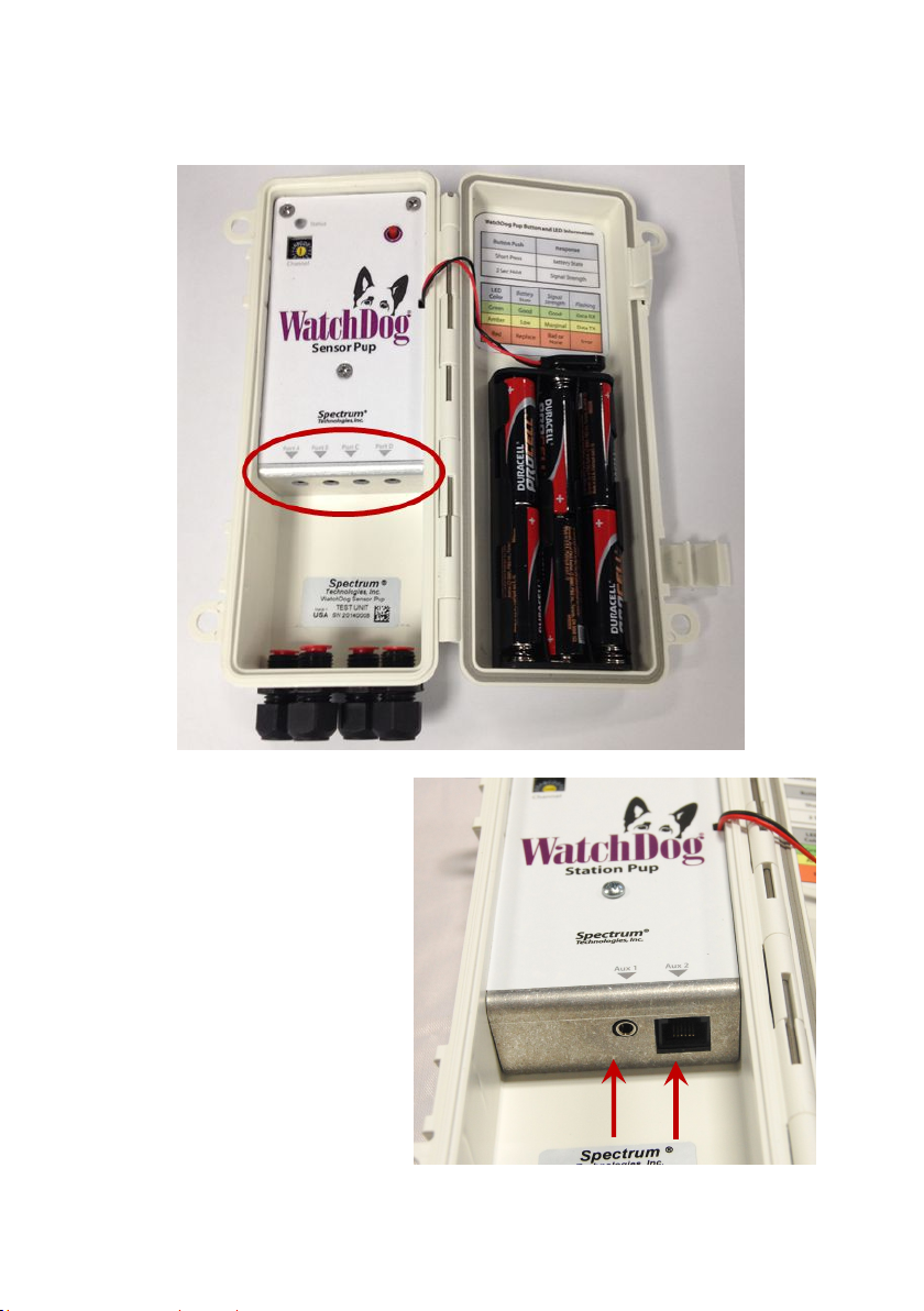
Sensor Pups
With the Sensor Pup, any WatchDog environmental sensor can
be connected to any port.
Station Pups
The Station Pup is shipped
with a cable with 2 modular
connectors. One end plugs
into the weather station’s
“AUX” port. The other end
plugs into the Station Pups
“Aux2” port. The Aux1 port
is not used.
Aux1
Aux2
7
Page 8
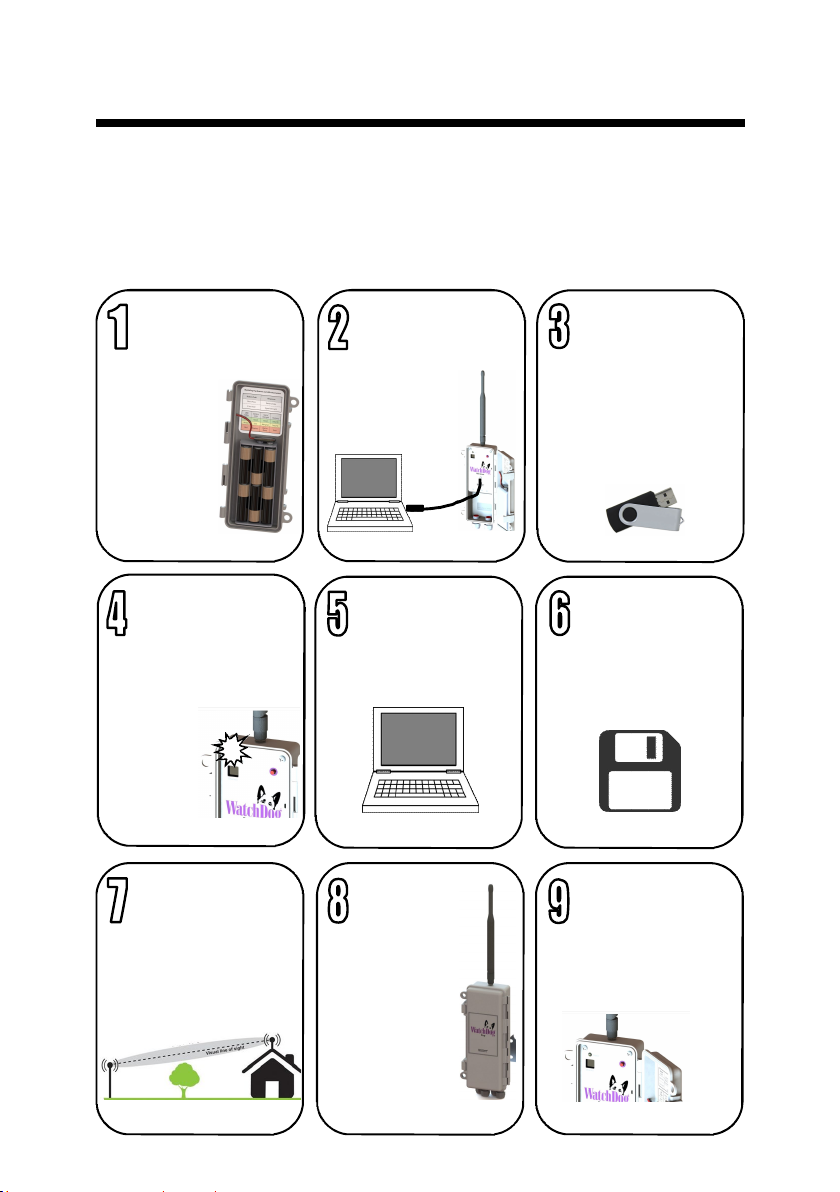
GETTING STARTED
Get your wireless network running in the following nine steps.
Use the My Network Library planning tool inside (p. 33) to
plan the configuration and layout of your Pups
(recommended)
Find a tutorial video online at www.specmeters.com/videos/
Power-up
Retriever
Retriever
should be in
Setup mode
(flashing
amber)
Connect its
antenna
pg. 9
Put batteries in
Pups
They will join the
Retriever’s network
(3 green flashes)
pg. 9
Deploy
Retriever
Place in a position to
achieve line-of-sight
communication to
nearest Pups
pg. 21 pg. 22
Connect to PC
or DataScout
Use USB cable
and PC port on
Retriever
Configure
units
Use RPLU or
SpecConnect
Deploy
Pups
Check signal
strength (2second press)
at their desired
locations.
Adjust as
necessary
pg. 21-22
pg. 10
Open launch
software or
power up
DataScout
RPLU program
loaded on USB flash
drive or on Spectrum
website
pg. 10
Save to
Retriever
Save settings from
RPLU or SpecConnect
pg. 10-17 pg. 10-17
Change to
Active mode
Return to Retriever
and switch mode (2second press)
8
Page 9
Setup
Installing the Retriever & Pup Launch Utility software (RPLU)
The installation program is available on the USB flash
drive that shipped with the Retriever and on the
Spectrum website. Run the RPLU setup.exe file to
install the launch utility. The RPLU desktop icon (right)
can then be used to open the program.
Powering Up and Syncing the Retriever and Pups
Follow these steps to set up the Retriever and Pups wireless
network.
1. Verify that all the Retriever and Pup units
are on the same channel by checking the
Network Channel Selection switch. If not,
use a screwdriver to change the channel
selection. If using multiple wireless
networks, each network should use a
unique channel.
2. Attach the antenna only to the Retriever.
3. Install batteries in the Retriever. The LED will flash green
while powering up. Following power-up, the Retriever should
be in Setup mode (flashing amber). If it isn’t, hold Retriever’s
button for 2 seconds.
4. Put the Pups within proximity of the Retriever and power
them up by installing the batteries. The LED will flash green
several times. They will automatically broadcast a request to
join the Retriever’s network following power-up. This is
indicated by several amber flashes (request to join) followed
by 3 quick, green flashes (successful reply). If the Pups don’t
automatically join within one minute, hold the Pup’s button for
8 seconds to manually join. The Retriever’s amber flash
sequence will accelerate. The Pup’s connection status can
also be seen in the RPLU software (p. 10)
5. See Configuration (pg. 10 - 17) for details on configuring
Retrievers, Sensor Pups, and Station Pups. Configuration
can be done with RPLU software. Retrievers connected to a
DataScout modem can also be configured with the
SpecConnect web utility.
9
Page 10
CONFIGURATION
A Pup can be configured by connecting directly to a PC, a USB
flash drive, or the SpecConnect web portal. The flash drive is
used when adding a Pup to a previously configured system that
is already in the field.
Configuration via Direct Connection to Retriever
If the Retriever is not in Setup mode (amber light flashing
continuously), hold the button for 2 seconds (see Retriever/Pup
Operation, pg. 18). Connect the Retriever to a Windows
computer using the USB to 3.5mm stereo plug cable (item
3661U, included). Open the RPLU program using the desktop
icon.
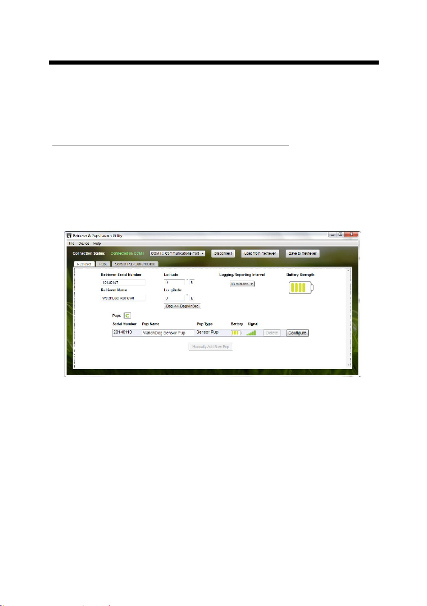
Figure 2. Retriever Settings Screen
1. Upon start-up, the RPLU will automatically recognize any
COM ports on your computer. If the Retriever doesn’t
automatically connect, select the COM port of the USB serial
cable and click the “Connect” button to establish communication
to the Retriever. If the list includes more than one COM port, you
can check in your computer’s Device Manager or simply go
through them one by one.
2. From the Retriever Settings screen (fig. 2), set the Retriever
parameters. The Retriever’s name is entered in the text box.
The logging interval is selected from the dropdown menu.
Entering latitude and longitude is optional. These can be entered
in decimal or Degree/Minute/Second format.
10
Page 11
3. A list of Pups will be visible on the Retriever settings screen.
Verify that the Pups are communicating with the Retriever. When
a Pup becomes active, the battery and signal icons will change
from gray to colored.
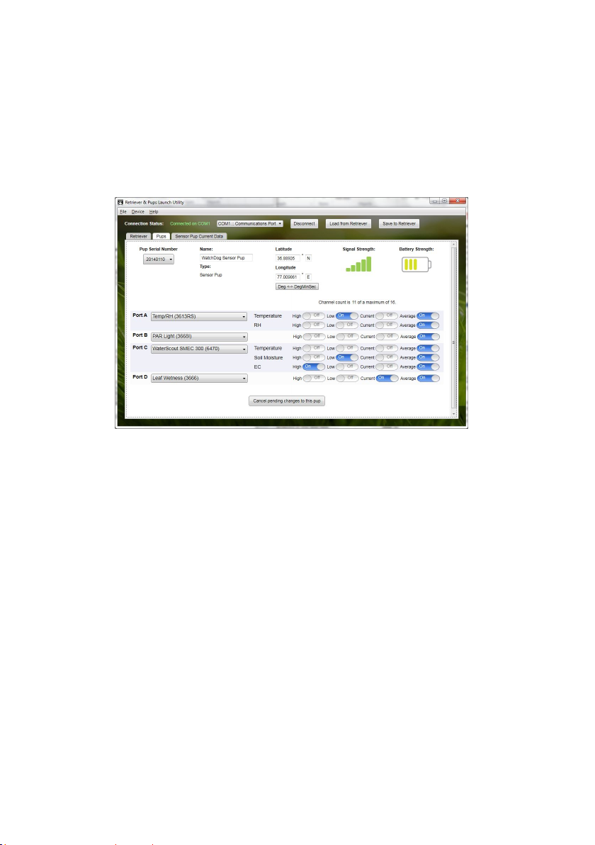
4. Clicking a Configure button will bring up Settings screen for
that specific Pup (fig. 3). The Pups settings screens can also be
brought up by clicking on the Pups tab.
Figure 3. Pup Settings Screen
5. Set the Pup’s parameters in the Pup Settings screen. The Pup’s
name is entered in the text box. The type is automatically
determined from the Pup’s serial number. Entering latitude and
longitude is optional. These can be entered in decimal or Degree/
Minute/Second format. Select the sensor type from the drop down
menu for each port. Select up to 4 channels per port using the
toggle buttons (see Data Logging & Storage, p. 24). Note that
most Pup stations have most sensors pre-defined.
6. To configure additional Pups, select each serial number in turn
from the “Pup Serial Number “dropdown menu on the Pup setting
screen. Alternately, you can select a Pup from the list on the
Retriever settings screen (see step 3).
7. Once the Retriever and all Pup units are set, click the “Save To
Retriever” button. The Retriever will wirelessly send the settings to
the Pups.
11
Page 12

8. Go to the Sensor Pup Current Data tab to verify the expected
data parameters are coming in from each pup. If a sensor is not
connected, a dash will be displayed in the Data Value column.
For Station Pups, the
current condition can
only be seen in the
Pups tab.
The Retriever can now be disconnected from computer.
Configuration via USB Flash Drive
The Retriever configuration can be stored to a flash drive and
transferred to a Retriever in the field. The configuration process is
similar to the one for the direct PC connection except the
Retriever and Pup information must be entered manually.
1. Insert the flash drive into the PC and
bring up the RPLU software. Open the
“File” menu (fig. 4).
2. If a configuration for the desired
Retriever is already stored on the flash
drive, click the “Open Configuration”
option to modify that configuration.
Skip to step 5.
3. For new setups, click the “New
Configuration” option to configure a new
Retriever. This will bring up the “Start a
New Configuration” screen. Enter the
serial number for the Retriever and click
“OK”.
4. In the Retriever Settings screen,
click the “Manually Add New Pup”
Button. This will bring up the “Add a
Pup to Retriever Configuration”
screen. Enter the serial number for
the Pup and click “Add”. Repeat this
process for all Pups.
Figure 4. RPLU File
menu
12
Page 13

5. The Pup(s) will appear in the Retriever Settings screen and as
an option in the Pup Settings screen. Begin the process as in
step 3 of the configuration for a directly connected Retriever (p.
10). When all Pups have been configured, click the “Save
Configuration As” option from the File menu (fig. 4). The program
will bring up a browser screen. Save the configuration to the root
directory of the flash drive. The configuration file will have the
name setup.txt.
Eject the flash drive from computer. In the field, put the Retriever
in Setup mode by pressing the button for 2 seconds (LED will
flash amber). Plug the flash drive into the Retriever. Initiate the
transfer of configuration settings with a short press of the button
(see Retriever/Pup Operation, pg. 18).
13
Page 14

Configuration via the SpecConnect Web Portal
1. Log in to your account at www.SpecConnect.net.
2. Open the Retriever configuration page by
clicking the “Equipment” option in the upper left
corner. Click on the “Configure” button for the
Retriever to bring up the Configure WatchDog
screen.
3. In the “Configure Retriever” screen (fig. 5), set the Retriever
parameters. The latitude, longitude & altitude (optional) can be
keyed in. Alternately, if the pindrop icon is clicked, a map image
will be displayed that allows you to locate the device. The logging
interval is how often a Pup sends data to the Retriever. The
Upload interval is how often the DataScout reports records to
SpecConnect. In most installations, it is recommended for the
logging interval to match the upload interval. See Data Logging
& Storage (p. 24) for details on the logging and web upload
intervals. Click “Save” to store any changes.
Figure 5. SpecConnect Retriever Configuration Screen
4. Return to the equipment list and open the first Pup
configuration page.
14
Page 15

5. In the “Configure Sensor Pup” screen (fig. 6), set the Pup
parameters. The latitude, longitude & altitude (optional) can be
keyed in. Alternately, if the pindrop icon is clicked, a map image
will be displayed that allows you to locate the device. See Data
Logging & Storage (p. 24) for details on setting the data
channels. Click “Save” to store any changes. Repeat for all Pups.
Figure 6. SpecConnect Pup Configuration Screen
6. The configuration will be sent to the DataScout modem which
communicates the settings to the Retriever.
15
Page 16

Configuring Weather Station Connected to a Station Pup
WatchDog 2000-series stations used with a Station Pup must be
configured* with SpecWare Pro software or with the WatchDog
Configuration Utility.
Requires SpecWare Pro v9.6 or later, update online at
www.specmeters.com/updates/
Minimum firmware requirements
Weather station (except model 2800) v 7.6
2800 Weather Station v 3.5
Mini Station v 4.1
Configure the WatchDog mini or full weather station using Spec9
Pro by following the steps below:
1. Connect the WatchDog mini or weather station to a PC.
2. In Specware 9 Pro, open the WatchDog Properties using the
WatchDog Manager or the ‘Launch/Set Properties for 1000 or
2000 Series’ button. In the WatchDog Configuration Utility, click
the “Configure” button.
3. Enter the name, logging interval, and sensor configuration
4. Set Repeat-Transmit Interval to Send Log Data at Log
Interval.
5. For mini stations set Format to 4 Text (RP/SC).
6. For full weather stations set Format to 5 Text (RP/SC).
7. Save the settings by clicking ‘OK’.
* No configuration is necessary if only the internal sensors are
used.
16
Page 17

8. Connect the 2000-series station to the Station Pup using the
provided cable.
9. The 2000-series station will send its logged data to the Station
Pup at the selected interval and the Station Pup will send this log
to the Retriever as part of the wireless network. This can be
confirmed by connecting the Retriever to the Retriever & Pup
Launch Utility. The latest data record will appear in the Pups tab
under the Station Pup’s serial number. These values are
updated every time the station logs a new data record.
17
Page 18

Retriever/Pup Operation
The LED on the Retriever or Pup is used to convey information
about the status and functioning of each device. The small red
button can be used to request most of this information. For
Retrievers, the button can also be used to prompt the device to
perform certain actions. A label summarizing these features is
affixed to the inside door of the device. These are explained in
greater detail below.
Retriever
The Retriever operates in one of two modes; Setup and Active. In
Setup mode, the Retriever interacts every 20 seconds with the
Pups. Therefore, information will be sent to, and received from,
the Pups more quickly. This mode is used when configuring the
system or when troubleshooting. This mode is indicated by a
flashing amber LED. While in Active mode, the Retriever and
Pups communicate every 5 minutes. This longer communication
interval is used to conserve battery life. To switch between Active
mode and Setup mode, press and hold the button for two
seconds. The LED will initially blink slowly but transition to rapid
amber flashing when the unit is in the new mode.
Retriever configuration and data transfer can be done with the
Retriever & Pup Launch Utility (p. 10), the SpecConnect Web
Portal (p. 14), or a USB flash drive (p. 12). If the Retriever is in
Setup mode, a short button press will instruct the Retriever to
read a USB flash drive for new configuration settings. If the
Retriever is in Active mode, a short button press will initiate two
actions; 1.) The LED will briefly indicate the battery strength and
2.) Any new data will be offloaded to the flash drive (see Data
Export - USB Flash Drive, pg. 26).
The Retriever will periodically flash green when it communicates
with the network of Pups. These green flashes will occasionally
overlap with other LED indications. The explanation of the
different LED colors is shown in figure 7.
18
Page 19

Pup
The red button on the Pup is used for in-field diagnostics. A short
press requests the battery strength. Pressing and holding for 2
seconds, until the LED turns on, prompts the Pup to indicate if it
has optimal communication with network. If the Pup does not
have desirable signal strength, find another location to deploy the
Pup or follow the recommendations in Installation (pg. 20). The
requested status is indicated by the LED. The explanation of the
different LED colors is shown in figure 8. Additionally, the LED on
the Pup will flash green when it is receiving data from the
Retriever and amber when it is transmitting data to the Retriever.
These green flashes will occasionally overlap with other LED
indications.
Figure 7. Retriever button and
LED information label.
Factory Reset
To issue a factory reset to either the Retriever or Pup units,
disconnect power and power-up the unit while holding the button
for 8 seconds, until the LED flashes red & green. Pups must
rejoin the network after disconnecting power, see instructions
above. If a Retriever is factory reset, the configuration of the unit
must be re-sent using the RPLU or SpecConnect (see Setup,
pg. 9)
Figure 8. Pup button and LED
information label.
19
Page 20

INSTALLATION
The Retriever and Pups will function optimally when the units are
placed in a condition that allows direct line-of-sight. The optimum
signal will occur when the football-shaped Fresnel Zone is clear
of obstructions such as hilly terrain, foliage, and structures.
The recommended clearance above crop height is at least 3
feet (1 meter). Higher installations give better performance.
The maximum range between Pups is 2500 ft (about ½ mile
or ¾ kilometer) for 900 MHz and 300 m for 2.4 GHz. The
most remote Pup should not exceed 4 hops back to the
Retriever.
To achieve line-of-sight communication when obstructions are
present, we recommend using:
Repeater Pups (item 3902/3907, see Components, pg. 5)
Route communication around obstructions
Antenna extensions (Item 3925 see Accessories, pg. 30)
Route communication above obstructions and allow
unit to be lower to ground, giving better access to
sensor ports and batteries.
20
Page 21

The Retriever and Pups should be configured before
deployment. Configuration should be done while communicating
in Setup mode (see Configuration, pp. 10 - 17).
Tools recommended for installation
7/16-inch (11-mm) wrench
Phillips screwdriver for tightening the mounting bracket
screws on back of units
Antenna stabilizer (included) prevents antenna from bending
when mounted vertically but can be removed to allow a bent
antenna for horizontal mounting
(see fig. 9).
Deploy the Retriever
1. It is important that the Retriever
antenna be placed as high and clear
of obstructions as possible, since all
Pup data is routed to the Retriever.
2. Mount using provided hardware
(bracket, u-bolt, nuts, screws).
3. Mount solar panel (if being used).
Connect to Retriever with DC
adapter (see p. 6).
Deploy the Pups
1. It is recommended to start with the
Pup that will be nearest to the
Retriever and move outwards to
create the mesh network.
2. Upon arrival at each desired
location, attach an antenna to the
Pup.
3. Check the signal strength of the
Pup at the location by holding the
Pup’s button for 2 seconds until the
LED turns on (see Retriever/Pup
Operation, pg. 18).
4. If signal strength is poor, move
closer to either the Retriever or
Figure 9. Retriever and
DataScout setup with
solar panel. Stabilizer
shown in inset photo
nearest Pup, use an antenna
extension, or add a Repeater.
21
Page 22

5. Mount using provided hardware and tighten screws using a
Phillips screwdriver (see fig. 10). Although the antenna should be
vertical, the housing can be oriented horizontally or vertically.
Figure 10. Attaching the mounting bracket.
6. Attach sensors - make sure the cable glands are tightened
around the sensor cables
Final Steps
1. After the last Pup is deployed, return to the Retriever and hold
the button for 2 seconds to enter Active mode (the LED’s will
stop flashing amber) which saves battery life. Otherwise, the
Retriever will automatically transition to Active mode after 4
hours.
2. After at least one logging interval, check that all the Pups are
communicating with the Retriever.
If using SpecConnect, check for current data on the
web portal.
If using a direct connection from the Retriever to a
PC, use the RPLU to check for current data.
If using the USB flash drive for data transfer, check it
in a PC to confirm Pup data files are being logged on
the flash drive (see Data Export, p. 26). Re-insert
flash drive in the Retriever.
22
Page 23

Adding a Sensor or Station Pup to an established network
Be sure the Retriever is in Setup mode (flashing amber). If it
isn't, press the button for 2 seconds. It may take up to 5 minutes
for the Retriever to transition to Setup mode.
Install batteries in the new Pup. The Pup will flash amber
while it tries to join. When successful, it will flash green 3
times. If it doesn't join, hold the red button on the Pup for 810 seconds. This will re-start the meshing sequence. The
Pup may or may not flash amber but will flash green 3 times
when it has meshed.
Once meshed, the Pup will periodically flash green and
amber to indicate communication to the Retriever.
23
Page 24

DATA LOGGING & STORAGE
Data Logging
The Retriever logs sensor data from its network of Pups
(maximum of 16 Pups per network).
The Pup logging intervals are: 5, 10, 15, 30, or 60 minutes.
Pups read the sensors every 15 seconds. So, for example,
the logged value for a Pup on a 5 minute interval will be
composed of 20 measurements.
A single logging interval is selected in the Retriever Settings
screen because all Pups have the same interval.
If communication to a Pup is lost for a period of time, all other
Pups will continue functioning normally. When noncommunicating Pups are reconnected, they will send all their
missing data to the Retriever.
Shorter intervals allow for more frequent updates to
SpecConnect, but also consume more modem battery power.
For installations with many Pups (10 or more), it may be
beneficial to set the upload interval to be shorter than the
logging interval.
Data Channels
Up to four data types, can be recorded for each sensor
measurement. These data channels are defined as follows:
Average: The average of all measurements taken during
the logging interval
Current: The most recent measurement
High & Low: The maximum and minimum values
measured during the logging interval
Each Sensor Pup can log a maximum of 16 data channels.
When using multi-sensors, a different configuration of data
channels can be chosen for each parameter.
Rain and wind sensors have pre-selected data channels.
Data Storage
The flash memory on the Retriever will hold approximately 6
months of data for a 10 Pup network using 15 minute logging
intervals. When the logging capacity is reached, older data
on the Retriever will be overwritten. To avoid loss of data if
the internal memory fills, it is recommended that the Retriever
always be connected to a USB flash drive.
24
Page 25

If communication to the Retriever is interrupted, the internal
memory on the Pups buffers sensor data for at least 21 hours
until a connection to the Retriever is re-established.
Non-volatile memory on the Retriever preserves the logged
data, even when power is lost.
Updating Firmware
A summary of the firmware update procedures are given below.
Full details on updating are available at
http://www.specmeters.com/assets/1/22/
Technical_Bulletin_20141204_Update_Retriever_Pups_Firmware.pdf
Retriever
Load the latest version of the Retriever firmware (retFw.bin)
onto the flash drive.
Remove all power from the Retriever and insert flash drive.
While holding the button, re-attach the battery.
Release the button when LED glows amber.
Update is complete when LED flashes green.
Retriever will return to Setup mode (flashing amber)
Pup
Load the latest version of the Pup firmware (sPupFw.bin for
the Sensor Pups and wsPupFw.bin for the Station Pups and
Repeater Pups ) onto the flash drive.
Pups must be paired with Retriever and the Retriever must
be in Setup mode (flashing amber).
Plug USB flash drive with firmware file into USB port on the
Retriever.
Press and quickly release button on Retriever to initiate file
transfer to the Pup. Retriever LED will flash red/green.
When the Pup's firmware is updated, its LED will briefly flash
red/green then return to normal operation.
Delete the Pup firmware from the flash drive.
25
Page 26

DATA EXPORT
Gathering Data on a USB Flash Drive
The USB flash drive can be left in the Retriever or temporarily
inserted to offload data stored in the Retriever’s memory. While
the flash drive is inserted, data is automatically saved to it. If the
flash drive is inserted only at the time of data collection, a manual
dump of the data is necessary. This is also true for instances
when the drive is normally left in the Retriever, but must be taken
off site temporarily to transfer the data. In that case, a quick data
dump should be done at insertion to capture data recorded during
that interval and before automatic data collection begins.
The Retriever creates a single file with all the historical data on
the Retriever. The name for this file will be the serial number of
the Retriever. This is the only file available for a flash drive
inserted at the time of data collection.
A flash drive left in the Retriever will also contain a unique data
file for each day of data stored on the Pups since it was last
plugged into the Retriever. Data files are in semicolon-delimited
text format. These daily files will have the naming convention
“YYYYMMDD.txt” where Y is the year, M is the month and D is
the day.
To offload data to a newly inserted flash drive, the Retriever must
be in Active mode (no regular LED flashing) before initiating the
download. If the Retriever is in Setup mode (LED flashing amber),
press and hold the button for two seconds to put it into Active
mode. While in Active mode, initiate the download by quickly
pressing and releasing the button. The LED will show the battery
state, then glow amber until the data transfer is complete.
It is recommended that data be cleared from the USB stick once it
is saved in a safe location.
26
Page 27

Importing Data with SpecWare Pro Software
(requires v. 9.6 or greater)
Pup data can be imported into Specware Pro. From the
main Specware screen, click the Retriever & Pups icon
from the toolbar. This will bring up the Retriever & Pups
screen (fig. 11).
There are 3 possible data sources
1. PC connected directly to Retriever
Connect the PC direct-connection cable to the “PC” port on the
Retriever. The COM port is selected in the File - Preferences Communication tab - Direct Connection field (fig. 12).
Figure 11. Specware Retriever & Pups screen
Click the Retriever button (fig. 11) to download the data
received from the Pups. The Erase records from Retriever
option is recommended to speed up download times
2. Transferring data from USB flash drive
Click the Log Files button (fig. 11) to browse for the data files
saved to a flash drive (see p. 26). You must browse to the
directory to pull data from. The default is the Specware
directory, not the flash drive.
Figure 12. Specware port selection screen
27
Page 28

3. SpecConnect Exports
In SpecWare, click File - Import Files - Import SpecConnect
Data Files to import a SpecConnect export file (fig. 13). See
SpecConnect Web Portal (below) for information on exporting
data from the web portal.
Exporting Reports From the SpecConnect Web Portal
Data exports from SpecConnect are done from
the Reports feature. Select the desired report
type from the Reports screen (fig. 14). Select
the Pup date range and any other necessary parameters
(equipment, sensors, ...) for the exported data file (fig. 15). Use
the export button to download the data. The data is stored in .csv
format.
Figure 13. Import SpecConnect Data Files button
28
Figure 14. Reports screen
Page 29

Figure 15. Sample report options screen
29
Page 30

ACCESSORIES
Optional Accessories
Tripod, item 3396TP
Antenna extension 10-ft cable and mounting hardware (item
3925)
AC-DC power cord (item 3926)
PC Direct-connection 50-ft cable kit (item 3297)
USB flash drive (item 3388USB)
75’ Powered Direct Connect 75 ft Retriever Extension Cable
Kit (3927C75)
DataScout Cellular or WiFi modem (multilple item numbers)
Tripod (item 3396TP)
AC-DC power cord
(item 3926)
30
10-ft antenna extension cable and
mounting kit (item 3925)
Page 31

Specifications
Mounting Hardware
Enclosure
Weight
Power Options
(non solar)
Power Options
(solar)
Battery Life
Operating
Temperature
PC/Aux Port
Baud Rate
Frequency bands 902-928 MHz ISM band:
1¼ inch u-bolt, aluminum bracket
3.75 x 2 x 8 in (9.5 x 5.2 x 20.2 cm)
IP65, UV resistant ABS plastic
Non Solar: 1.6 lb (0.7 kg)
Solar: 5.5 lb (2.5 kg)
6 x AA batteries,
DC power port (maximum 17 VDC)
5W solar panel with Rechargeable
battery pack
(2200 mAh, 7.2 NiMH)
8 months (typical)
-22 to 130 °F (-30 to 55 °C)
(with non-rechargeable AA batteries)
14 to 130 °F (-10 to 55 °C)
(with rechargeable NiMH battery pack)
9600 bps (default, adjustable)
(3900, 3901, 3902, 3910, 3910S
2.4 GHz ISM band:
(3905, 3906, 3907, 3911, 3911S
Antenna
Range 900 MHz: 2500 ft (~750 m), line of sight
Output Power 900 MHz: 2500 27dBm (500mW) with
Reverse polarity SMA
2.4 GHz: 300 m
omni-directional antenna (included)
2.4 GHz: 10 dBm (10 mW)
31
Page 32

Power
Pups
Standard Pups are powered by 6 AA batteries. The battery status
can be checked by quickly pressing and releasing the button.
Any time the batteries are changed on a Pup, it must rejoin the
network. This is done when the unit powers on or by holding the
button for 8 seconds. The LED will rapidly flash green 3 times
when it has joined.
Retrievers
Standard non-solar retrievers are powered by 6 AA batteries. A
solar retriever uses a 6-cell NiMH battery pack. When connected
to a DataScout, the units will share power. If using an AC-DC
adapter or PC direct-connection cable to power the Retriever, it
is recommended that the 6 AA batteries be removed after the
DataScout (or other constant power source) is connected. The
solar panel or AC-DC adapter will keep the attached unit
powered without need of additional batteries. While no immediate
damage will occur if the alkaline batteries are left in, unused
alkaline batteries tend to corrode over time and can damage the
device.
A solar Retriever (3910S) can also be connected to an AC-DC
adapter or PC direct-connection cable. However, the
rechargeable battery pack must remain connected at all times.
Changing batteries in a Pup in the field
The procedure is the same as for adding a new Pup (p. 23).
Changing batteries in Retriever or restarting a system if
Retriever powers off
Simply replace the batteries in the Retriever. The Retriever will
start up in Setup mode (flashing amber) and begin looking for all
the Pups it has previously communicated with. If a new Pup is
being added to the system, it is recommended that the new Pup
be powered up after powering up the Retriever so it meshes
faster. Otherwise, the Pup can be put into setup mode by
pressing the button for 8-10 seconds. In that case, it may take up
to 5 minutes for the Retriever to transition to Setup mode.
32
Page 33

MY NETWORK LIBRARY
Use this table to keep track of information about your Retriever &
Pups Wireless Sensor Network.
Plan out your sensor network before deploying
Take notes while deploying the network
Keep an equipment library for future reference
Serial Number Name / Location Sensors
A: C:
B: D:
A: C:
B: D:
A: C:
B: D:
A: C:
B: D:
A: C:
B: D:
A: C:
B: D:
A: C:
B: D:
A: C:
B: D:
A: C:
B: D:
A: C:
B: D:
A: C:
B: D:
A: C:
B: D:
33
Page 34

Troubleshooting Guide
1. The RPLU will not communicate with the Retriever.
Check your PC’s Device Manager to see if the computer
recognizes the USB cable. The driver should automatically
download if the PC is connected to the internet. Also available at
www.specmeters.com/updates/
Only one program can communicate with the USB cable at a time
(SpecWare and RPLU can interfere with each other. In this case,
close both programs then reopen the one to be used
2. The LED doesn’t flash at all.
Check that the snap connector is securely connected to the
battery holder and that all the AA batteries are inserted in the
correct orientation.
3. Single Pup not being updated in SpecConnect
- Confirm that the Pup is on the same channel as the rest of the
network.
- The batteries may be dead. Check last reported value for
battery strength in SpecConnect and/or visit the site and perform
a quick press.
- Check to see if the Pup is knocked to the ground or damaged.
This includes water damage or corrosion inside the housing.
- Check the signal strength of the Pup at location.
See Setup (p. 9) for instructions on how to sync the Pup with the
Retriever. After successfully meshing the Pup, perform a 2second press on the Retriever button to return it to Active mode
(flashing amber).
4. Single Pup being updated intermittently in SpecConnect
Check that the antenna is firmly attached in an upright
orientation, is not blocked by foliage, and is sufficiently above the
crop canopy.
34
Page 35

5. No Pups are being updated in SpecConnect
This is most likely the result of a problem with the modem or the
Retriever.
- Check for damage or water in the Retriever and modem
enclosures.
- Check that the Retriever is getting power (batteries or solar
panel).
- Check that the modem has power (quick push of button) and
good signal strength (2-second button push).
- Check that the modem and Retriever antennas are firmly
attached in an upright orientation.
6. Not seeing data from an individual Pup sensor
- Check that sensors are fully seated in port connectors.
- Check sensor wires for damage.
- Swap sensors (and reconfigure through SpecConnect or
RPLU) to check for potential port failure.
Regulatory Information
900 MHz:
USA: FCC ID – MCQ-XB900HP
Canada: IC – 1846A-XB900HP
2.4 GHz:
Europe: CE, ETSI approval
Japan: Telec R201WWog215111
Australia: C-Tick approval
35
Page 36

WARRANTY
This product is warranted to be free from defects in material or
workmanship for one year from the date of purchase. During the
warranty period Spectrum will, at its option, either repair or replace
products that prove to be defective. This warranty does not cover
damage due to improper installation or use, lightning, negligence,
accident, or unauthorized modifications, or to incidental or
consequential damages beyond the Spectrum product. Before
returning a failed unit, you must obtain a Returned Materials
Authorization (RMA) from Spectrum. Spectrum is not responsible for
any package that is returned without a valid RMA number or for the loss
of the package by any shipping company.
DECLARATION OF CONFORMITY
Spectrum Technologies, Inc.
3600 Thayer Court
Aurora, IL 60504 USA
Model Numbers: 3900, 3901, 3902, 3910, 3910S, 3905, 3906, 3907, 3911, 3911S
Description: WatchDog Retriever & Pup Mesh Network
Type: Electrical equipment for measurement, control, and laboratory use
Directive: 2014/30/EU EMC
Standards: EN 61000-6-1: 2007
EN 61000-6-3: 2007
IEC 61000-4-2: 2008
IEC 61000-4-3:2006, +A1:2007 +A2:2010
EN 55022:2010
Paul Martis, Project Manager—Weather March 11, 2015
USA and Canada Conformity Standards:
FCC Part 15 CFR Title 47: 2014
ICES-003: 2012 Digital Apparatus (Industry Canada)
Spectrum Technologies, Inc
3600 Thayer Court
Aurora, IL 60504
(800) 248-8873 or (815) 436-4440
Fax (815) 436-4460
E-Mail: info@specmeters.com
www.specmeters.com
36
Rev. 8/2016
 Loading...