

WATANABE ELECTRIC INDUSTRY CO., LTD AP-244A-11 series, AP-244A-12 series, AP-244A-13 series, AP-244A-14 series Instruction Manual
(1)The application of voltage or current exceeding its maximum
allowable value to the input terminals may result in instrument
damage.
(2)The supply of power out of its allowable range may cause fire,
electric shock or instrument failure.
(3)The content of this manual may subject to change without prior
notice for product improvement.
(4)This manual is carefully prepared. However, if any question
arises, or any mistake, omission or suggestion is found in the
content of this manual, contact your nearest our sales agent.
1.Before operation
1-1 Checking Model No.
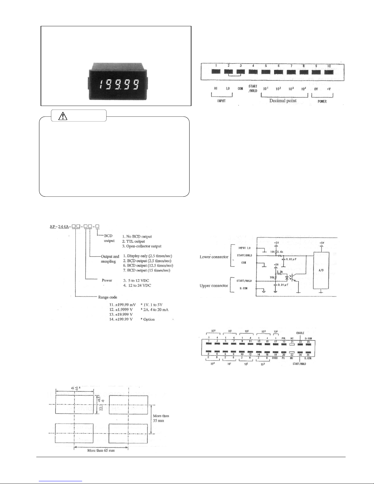
Each of AP-244A Model Nos. is configured as shown in the following,
check that the Model No. ordered matches that delivered.
1.2 Checking accessories
The following accessories will come with the AP-244A.
Lower 10-pin connector・・・・・1 pc.
Instruction manual・・・・・・・1 copy
Upper 26-pin connector・・・・・1 pc.
(Only with BCD output)
If you have any query, please contact our sales agent or Watanabe
directly.
1.3 Mounting
1.3.1 Panel cutout dimensions
Make the panel cutout for mounting the AP-244A according to the
following Fig.
1.3.2 Mounting the AP-244A
When mounting the AP-244A in the panel, push the meter in the panel
from the panel front while pressing down the snaps located at the
sides of the case.
1.4 Terminal connection diagram
*Do not gradually apply the power supply voltage to the meter but
from 0V quickly to the rated voltage. (If the voltage is gradually
increased, the meter may not start.)
2. Various functions
2.1 Setting the position of decimal point
The position of the decimal point of this meter can be externally
controlled from the lower connector terminals. Short the terminal
corresponding to the digit to be lit with the COM terminal.
2.2 Start/hold function
The start/hold function is used to control display hold
(measurement stop) and start (measurement start) from the external
control terminals.
Measurement is held with the START/HOLD terminal shorted with the
COM terminal (or level 0) or started with the START/HOLD terminal
opened from the COM terminal (or level 1).
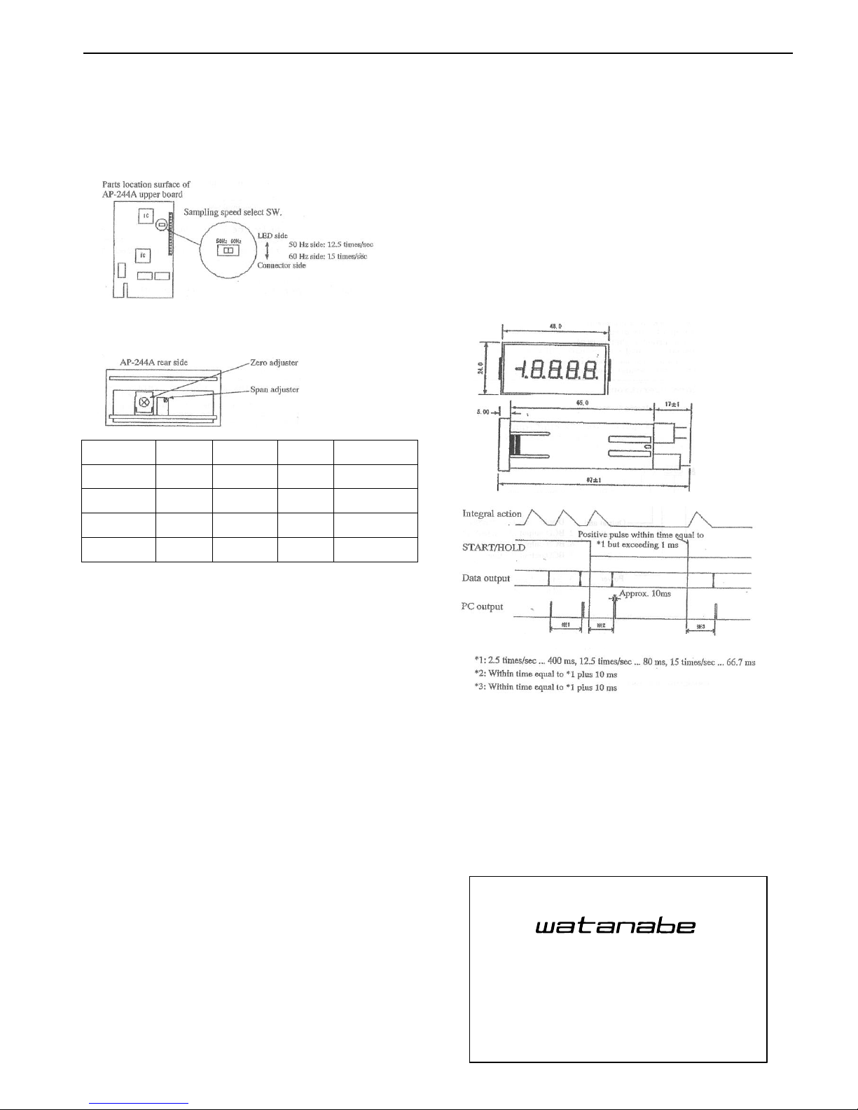
In addition, a positive pulse within one-sampling time exceeding
1 ms enables one-shot measurement.
The function of the START/HOLD terminal wired on the upper side
when the BCD output is optionally provided is the same as that
described above.
However in this case, the control line is isolated from the input
signal line.
2.3 BCD output
This meter can provide the parallel BCD output as option. In
addition, for the BCD output of this meter, the input circuit is
isolated from the power circuit.
2.3.1 Terminal connection diagram
2.3.2 Output status[( );For TTL]
Measured data;
Negative logic (Positive logic)
Polarity signal;
Transistor turned on at plus (Logic 1)
OVER signal;
Transistor turned on at OVER (Logic 1)
Printing command output (PC);
Transistor turned on (Logic 1) for about 10 ms every time
measurement is complete.
Output capacity;
Max. voltage 30V
Max. current 15 mA (Fanout 2)
INSTRUCTION MANUAL
DIGITAL PANEL METER
MODEL AP-244A SERIES
Caution
WATANABE ELECTRIC INDUSTRY CO., LTD.
2.3.3 ENABLE
All of the transistors are turned off for the open -collector output
or they are set to the high impendance state for the TTL output
with the ENABLE terminal shorted with the D.COM terminal or set
to level 0.
2.4 Selecting sampling speed
Select a sampling speed of 12.5 times/sec (50Hz) or 15 times/sec
(60Hz) depending on the commercial power frequency used. (If the
incorrect frequency is selected, the meter operates as usual but
its display may widely fluctuate.)
3. Calibration
In order to calibrate this meter, a standard voltage generator with
an accuracy of ±0.01% or higher is required. In addition, for
calibration, see the following Fig.
4.Specifications
Model No./
range codes
Measurement range
Max.
resolution
Input
impedance
Max.allowable
Input Voltage
AP-244A-11-
XX-X
±
199.99mV
10μV
100MΩ
±100V
AP-244A-12-
XX-X
±
1.9999V
100μV
100MΩ
±100V
AP-242A-13-
XX-X
±
19.999V
1mV
1MΩ
±250V
AP-242A-14-
XX-X
±
199.99V
10mV
1MΩ
±250V
Accuracy: ±(0.03% of rdg. +1 digit) at 23℃±5℃
■General specifications
Measurement
function
:DC voltage measurement
Operation method
:Double integral
Input circuit
:Single-ended type
Max. display
: 19999
Sampling speed
:2.5 times/sec.
12.5 times/sec(50Hz) or
15 times/sec(60Hz)
Noise rejection
ratio
:NMR, More than 50dB(50/60Hz)
Overrange warning
:”0000” or “-0000”flashes for an
input signal of more than 19999.
Display
:7-segment LED
(Red light emitting diode numeric
element) character height, 8mm
Polarity display
:”-“is automatically displayed when
the computation result is minus.
External control
:HOLD・・・
Shorting START/HOLD terminal with
COM terminal(or level 0)
START・・・
Opening START/HOLD terminal from COM
terminal (or level 1)
Operating temp/
humidity range
: 0 to 50℃/
35 to 85%RH
Power supply
: 5 to 12V DC ±5%
12 to 24V DC ±10%
Consuming current
:At 5V DC・・・
Approx.100mA(BCD not provided)
Approx. 220mA(BCD provided)
At 12V DC・・・
Approx.50mA(BCD not provided)
Approx. 100mA(BCD provided)
At 24V DC・・・
Approx.30mA(BCD not provided)
Approx. 60mA(BCD provided)
Dielectric
strength
:Between LO input and 0V power
terminals・・・
For 1 min. at 500V DC
Between LO input and D.COM output
terminals・・・
For 1 min. at 500V DC
Between 0V power and D.COM output
terminals・・・
For 1 min. at 500V DC
Between LO input terminal and
case・・・
For 1 min. at 1500V AC
Insulation
resistance
:Between each terminal described
above・・・
More than 100 MΩ at 500V DC
Dimensions
:48(W)×24(H)×87(D)mm
Weight
:Approx. 50g
Accessories
: Lower 10-pin connector・・・1pc.
Instruction manual・・・・・ 1 copy
Upper 26-pin connector・・・1pc.
(Only for BCD output)
5. Dimensions
6. Timing chart
7. Warranty and after-sale service
1) Warranty
This meter is warranted for a period of one year form date of
delivery. Any defect which occurs in this period and is
undoubtedly caused by Watanabe's faults will be remedied free of
charge. This warranty does not apply to the meter showing abuse
or damage which has been altered or repaired by others except as
authorized by Watanabe Co.,Ltd.
2) After-sale service
This meter is delivered after being manufactured, tested and
inspected under strict quality control. However, if any problem
does occur, contact your nearest Watanabe sales agent or Watanabe
directly giving as much information on problem as possibl e.
6-16-19, Jingumae, Shibuya-ku, Tokyo 150-0001, Japan
Phone: (81)3-3400-6140
Homepage http://en.watanabe-electric.co.jp/
WATANABE ELECTRIC INDUSTRY CO., LTD.
ASAHI KEIKI DIVISION
6-16-19, Jingumae, Shibuya-ku, Tokyo 150-0001, Japan
Phone: (81)3-3400-6141
Homepage http://www.watanabe-electric.co.jp/en/
WATANABE ELECTRIC INDUSTRY CO., LTD.
MODEL AP-244A Series ED-50092c (2/2)
 Loading...