

WATANABE ELECTRIC INDUSTRY CO., LTD AL-512 SERIES Instruction Manual
(1)The application of voltage or current exceeding its maximum
allowable value to the input terminals may result in instrument
damage.
(2)The supply of power out of its allowable range may cause fire,
electric shock or instrument failure.
(3)The content of this manual may subject to change without prior
notice for product improvement.
(4)This manual is carefully prepared. However, if any question
arises, or any mistake, omission or suggestion is found in the
content of this manual, contact your nearest our sales agent.
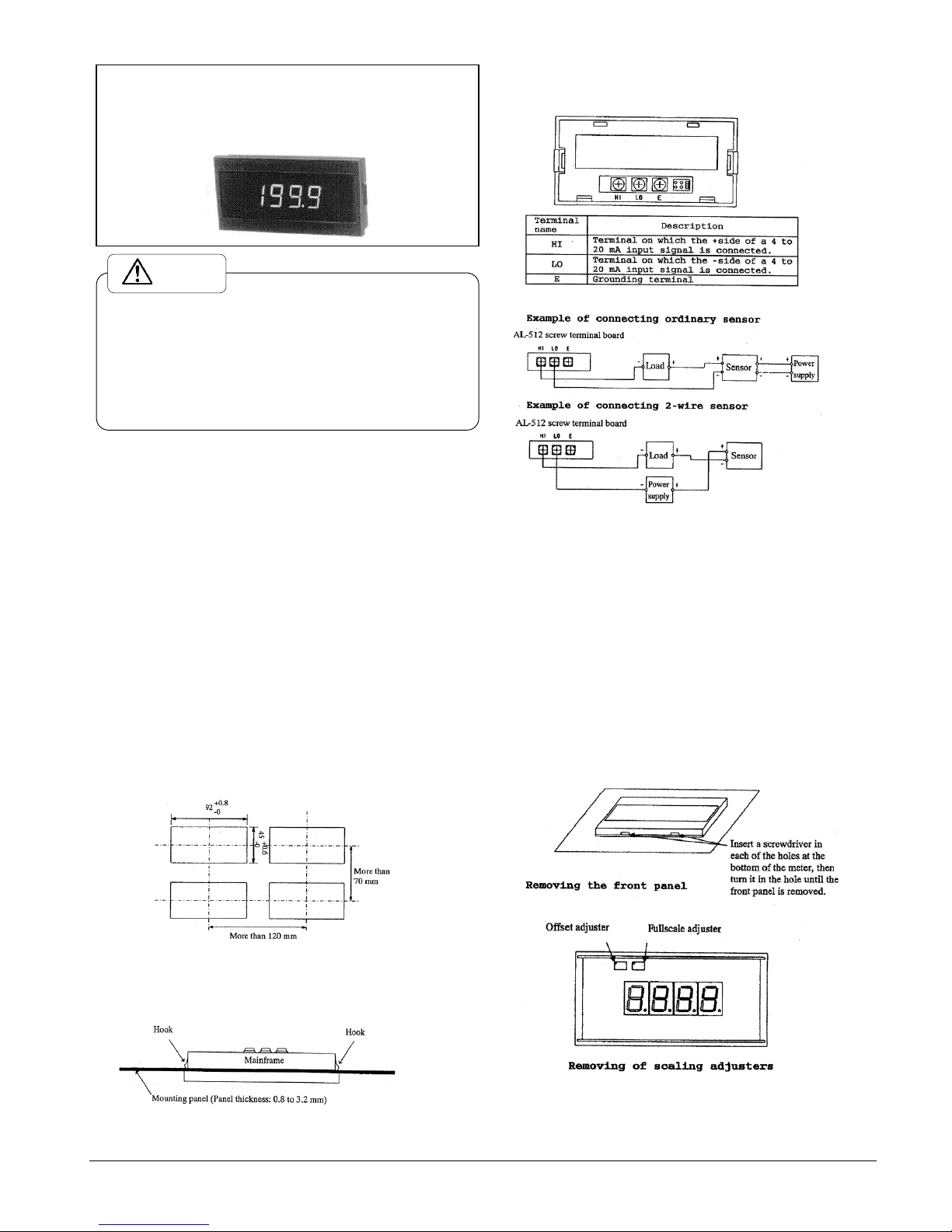
2.3. Terminals
2.4. Connection examples
1.Outline
The Model AL-512 digital panel meter is a process monitor which
has an extremely thin 3-1/2 digit LED display unit and also does
not require a power supply (driven by a 4 to 20mA signal).
It is provided with the display having a maximum of 1999 and the
scaling function by which the input signal can be converted to any
process variable for its display. In addition, wiring can be easily
conducted by the use of a screw terminal board.
2.Before operation
2.1. Accessory check
The following accessories are attached to one Model AL-512 digital
panel meter.
Instruction manual One copy
Screw terminal cover 1 pc.
If any question may arise on these accessories, please contact your
nearest Watanabe sales agent or Watanabe directly
2.2. Mounting
2.2.1. Panel cutout dimensions
Prior to mounting the meter, make the cutout through the panel as
shown in the following figure.
Panel cutout dimensions
2.2.2. Mounting
For mounting the meter, insert it in the panel cutout from the front
of the panel while pushing the hooks on both sides of the case in
the case. (See the following figure.)
Mounting diagram
*The Model AL-512 meter produces a voltage drop of about 5.3V
(at an input of 20mA).
For this reason, conduct wiring in consideration of the impedance
in the entire circuit.
*If this meter is used at a noisy location, ground the E (earth)
terminal.
3. Functions
3.1. Scaling adjustment
First, remove the front panel of this meter by referring to the
following figure. Then, turn the Offset adjuster (see the following
figure) until the desired value is displayed (setting range: ±
200) with an input signal of 4mA applied to the input terminals
on the meter.
Next, turn the Fullscale adjuster (see the following figure) until
the desired value is displayed (setting range: 100 to 1999) with an
input signal of 20mA applied to the input terminals.
*Prior to conducting scaling adjustment, allow more than 20 minutes
for the meter to warm up.
INSTRUCTION MANUAL
DIGITAL PANEL METER
Caution
MODEL AL-512 SERIES
WATANABE ELECTRIC INDUSTRY CO., LTD.

3.2 Decimal point setting
Prior to factory shipment, the decimal point of this meter is so
set that its position corresponding to the 101 digit is lit, change
the position of the decimal point by referring to the following
figure.
4. Calibration
In order to calibrate the meter, a current generator with an accuracy
of ±0.01% or more is required. This calibration is conducted in
the same manner as 3.1 Scaling adjustment.
5. Specifications
Model
Measuring
range
Display
Max. allowable
input current
AL-512
4 to 20mA DC
Offset;±200
Fullscale;
100 to 1999
±50mA
Accuracy: ±(0.1% of FS +1 digit)(23℃±5℃ and 35 to 85% RH)
Measurement function
: Measurement of instrumentation
signal(4 to 20mA DC)
Operation
:Double integral type
Maximum display
:1999
Sampling speed
:2.5 times/sec.(TYP)
Noise rejection ratio
:NMR 40dB (TYP)
Temperature
characteristics
:Offset displayed-value:
±0.3 digit/℃
Fullscale displayed-value:
±0.3 digit/℃
Overrange warning
:For an input of more than 1999, “1”
is displayed in the most
significant digit and the lower 3
digits go out.
Variable span of
fullscale
:100 to 1999
Variable span of
offset
:±200
Voltage drop
:5V at an input of 4mA(TYP)
5.3V at an input of 20mA(TYP)
Display
:7-segment LEDs (Red light emitting
diode numeric elements)
Character height, 14.2mm
Polarity display
:”-“ is automatically displayed
when the computation result is
minus.
External control
:None
Operating temperature
/humidity range
:0 to 50℃/ 35 to 85%RH
Power supply
:None (Driven by input signal)
Dielectric strength
:Between input terminal (LO) and E
terminal; For 1 min. at 500V DC
Dimensions
:96(W)×48(H)×22(D)mm
Weight
:Approx 55g
Accessory
:Screw terminal cover 1 pc.
Instruction manual 1 copy
Conformity standard
:EN61326-1: 2006
6. Dimensions
7. Warranty and After Sales Service
7.1 Warranty
The warranty lasts for one year from the date of delivery. If this
product fails during this period and the reason is considered to
be clearly.
The manufacturer warrants to the original retail customer its
indicator to be free of defects in material and workmanship for
use under normal care and will repair or replace any
7.2 After Sales Service
Under strict quality control measures, this product was
manufactured, tested, inspected and shipped. Should a defect in
manufacture or Workmanship be identified, please return the
product to our distributor or directly to us. It would be highly
appreciated if you could give a detailed account of the fault and
enclose it with the product.
Model AL-512 Series ED-49982c
WATANABE ELECTRIC INDUSTRY CO., LTD.
6-16-19, Jingumae, Shibuya-ku, Tokyo 150-0001, Japan
Phone: (81)3-3400-6140
Homepage http://en.watanabe-electric.co.jp/
ASAHI KEIKI DIVISION
WATANABE ELECTRIC INDUSTRY CO., LTD.
6-16-19, Jingumae, Shibuya-ku, Tokyo 150-0001, Japan
Phone: (81)3-3400-6141
Homepage http://www.watanabe-electric.co.jp/en/
 Loading...