

WATANABE ELECTRIC INDUSTRY CO., LTD AI-406 SERIES, AI-406-12, AI-406-11, AI-406-22 Instruction Manual
(1)The application of voltage or current exceeding its maximum
allowable value to the input terminals may result in instrument
damage.
(2)The supply of power out of its allowable range may cause fire,
electric shock or instrument failure.
(3)The content of this manual may subject to change without prior
notice for product improvement.
(4)This manual is carefully prepared. However, if any question
arises, or any mistake, omission or suggestion is found in the
content of this manual, contact your nearest our sales agent.
(5)After read this manual, please keep it as anytime can see.
1.OUTLINE
The AI-406 BCD input panel indicator is a highly reliable 6 digits
parallel BCD input indicator based on a one chip LSI. It conforms
to DIN external standards dimensions of 96mm(W)×24mm(H).
This meter is powered by 5V DC and 12V DC and has large 14.2mm LEDS.
Decimal point selection, data latching and leading zero
suppression are all externally access able at the carded age
connector.
2.SPECIFICATIONS
Model&Code
Input Level
Input pull up
Resistance
Power
Supply
AI-406-11
3.5V≦H≦5.0V
0.0V≦L≦1.5V
4.7kΩ
DC5V
AI-406-12
100kΩ
DC5V
AI-406-22
10.0V≦H≦12.0V
0.0V≦L≦2.0V
100kΩ
DC12V
●Model No. configuration ※AI-406-21 is Impropriety
3.COMMON SPECIFICATIONS
Maximum Display
:999999
Display
:LED numeric element height, 14 .2mm
Zero Display
:Leading zero on the upper display are
not shown
External control
:Data Latch;
Latch terminal and 0V terminal
(short)
BCD Data Latch Display
Decimal Points
:Can be set at desired position
Operating
Temperature
:0 to 50℃
Power Supply
:5V DC±10% MAX.35mA/digit
12V DC±10% MAX.33mA/digit
Dimensions
:96mm(W)×24mm(H)×96.5mm(D)
Weight(Unit only)
:Approx. 0.2 Ibs
Accessories
:Instruction Manual and Connector
4.HANDLING
4-1 General Caution and Preparation Prior to Operation
1)This instrument should be used at an ambient temperature between
0 and 50℃ and humidity of 85% or less, paying special attention
to dew condensation.
2)It must be used in an environment free of dust, dirt, gases and
chemicals harmful to electronic components.
3)Care should be taken to prevent vibration and shock.
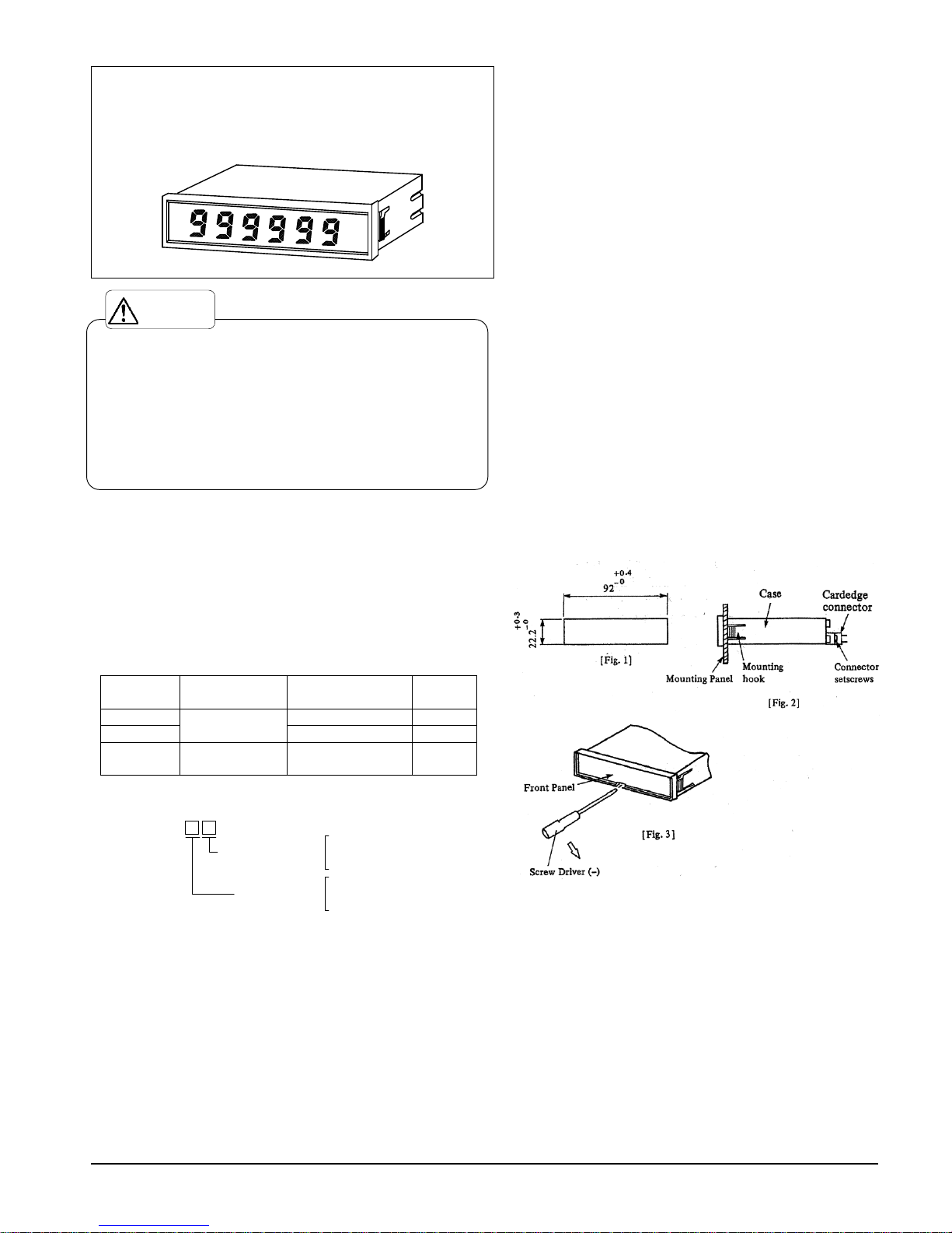
4-2 Mounting
1)Panel mounting
Make a rectangular cutout as shown in Fig.1, insert the
instrument in the panel as shown in Fig.2, and then fully push
the instrument into the panel (It’s recommended that panel
thickness be from 1 to 4mm.)
2)Removal of the PC board
Insert a screwdriver into the center on bottom of the meter and
twist so that the front panel comes. Then, push the printed
circuit board from the back and pull it out from the front.
(Fig.3)
(2)Removal of the PC board
Insert a screwdriver into the center on bottom of the meter and
twist so that the front panel comes off. Then, push the printed
circuit board from the back and pull it out from the front.
(fig.3)
4-3 Connector Connection
Insert the attached cardedage connector at the rear of the
indicator. The connector is provided with an insertion key to make
sure that it is not connected upside down. After insertion,
tighten both sides with the attached screws.
1)Power connection
Connect power to connector terminals Nos. 17 or U and 18 or V(+).
Use a DC voltage of 5V±10% (AI-406-11, AI-406-12) and 12V±10%
(AI-406-22)
(Note that because this instrument is not provided with a power
supply switch, it starts operating when power is supplied.)
INSTRUCTION MANUAL
BCD INPUT PANEL INDICATOR
MODEL AI-406 SERIES
Caution
WATANABE ELECTRIC INDUSTRY CO., LTD.
AI-406-
Pull-up Resistors
1:4.7kΩ (TTL level)
2:100kΩ
1:DC5V
2:DC12V
Power supply
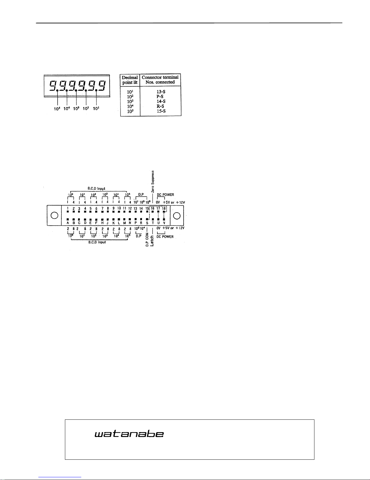
2)Decimal point setting
The decimal point can be set to any position when the following
connector terminals are shorted. However, because the decimal is
not set prior to shipment, it must be set at the appropriate
position by the customer. Leading zero suppression must also be
set if required.
3)Input connection
Connect an input signal (BCD parallel signal) as the following
connector diagram shows. Use a short connection cable and 2-core
shielded cable near a signal source.
■Connector Connection Diagram
(-----connected inside)
4)latch
Latch terminal (T) Open or Connect to +VDO (18,V), BCD Input data
display.
Latch terminal (T) and 0V terminal (17,V)short, BCD Input data
display.
5)Decimal point common terminal(S)
This terminal used for decimal point selection only.
5.MAINTENANCE AND INSPECTION
5-1 Caution for maintenance
The storage temperature of this instrument should be within the
range -10℃ to +70℃ with relative humidity not higher than 60%.
If the instrument is used at a dusty location, withdraw the meter
assembly from the case at certain intervals and brush off any dust.
(The combination of dust and high temperature will shorten the
life of the meter parts.) The instrument case and bezel are
molded plastic, do not use a volatile-liquid such as thinner to
clean them.
6.WARRANTY
The warranty lasts for one year from the date of delivery. If this
product fails during this period and the reason is considered to
be clearly.
The manufacturer warrants to the original retail customer its
indicator to be free of defects in material and workmanship for
use under normal care and will repair or replace any.
7.AFTER SALES SERVICE
Under strict quality control measures, this product was
manufactured, tested, inspected and shipped. Should a defect in
manufacture or Workmanship be identified, please return the
product to our distributor or directly to us. It would be highly
appreciated if you could give a detailed account of the fault and
enclose it with the product.
MODEL AI-406 SERIES ED-49981c
WATANABE ELECTRIC INDUSTRY CO., LTD.
6-16-19, Jingumae, Shibuya-ku, Tokyo 150-0001, Japan
Phone: (81)3-3400-6140
Homepage http://en.watanabe-electric.co.jp/
ASAHI KEIKI DIVISION
WATANABE ELECTRIC INDUSTRY CO., LTD.
6-16-19, Jingumae, Shibuya-ku, Tokyo 150-0001, Japan
Phone: (81)3-3400-6141
Homepage http://www.watanabe-electric.co.jp/en/
 Loading...