

WATANABE WPMZ-3 Series Instruction Manual

Graphical Digital Panel Meter WPMZ-3 INSTRUCTION MANUAL
IM-0883-01
Graphical Digital Panel Meter
[Straingauge/ Process]
Instruction manual
WPMZ-3-□□□-□□-□□□
Watanabe Electric Industry Co., Ltd.

Graphical Digital Panel Meter WPMZ-3 INSTRUCTION MANUAL
1
IM-0883-01
INTRODUCTION
Thank you for purchasing our graphical digital panel meter the WPMZ series.
This manual describes the functions, instructions on installing and wiring, operations etc.
Before using this product, please read this manual carefully and use the product correctly.
The latest manual can be downloaded as a file from our web site (http://watanabe-electric.co..jp/en/).
The file is in the PDF format and has the bookmark function for your convenience.
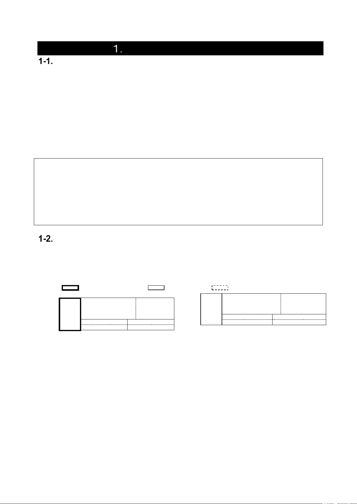
SUPPLIED ITEMS
Check that all the following items have been included in the delivered package.
item name
Quantity
Graphical panel meter WPMZ (body)
1
Case fixing attachment
2
Terminal block cover
1 (For supply power terminal)
Attached
connectors
1 input / no output
model
2(7P×1, 13P×1)
1 input / with output
model
3(7P×2, 13P×1)* Not BCD output
3(7P×1, 13P×1, 34P×1)*BCD output
2 inputs / no output
model
3(7P×2, 13P×1)
2 inputs / with output
model
4(7P×3, 13P×1)* Not BCD output
4(7P×2, 13P×1, 34P×1)* BCD output
Quick instruction manual
1
NOTES
・This manual covers WPMZ-3-***-**-*** of version V1.00 or later.
・This manual is subject to change without notice for improvements of the product.
・Keep this manual with close reach of persons who use this product to provide for future use.
Graphical Digital Panel Meter WPMZ-3 INSTRUCTION MANUAL
2
IM-0883-01
Table of contents
If you read this manual on a pc, you can jump to linked destination by clicking characters in blue.
PRECAUTIONS FOR USE ................................................................... 8
ENVIRONMENTS AND CONDITIONS OF USE ............................................................................... 8
INSTALLATION AND CONNECTION ................................................................................................ 8
CHECKING BEFORE USE .................................................................................................................. 9
CHECKING FOR ABNORMALITIES .................................................................................................. 9
MAINTENANCE AND INSPECTION ................................................................................................. 9
DISPOSAL OF THIS PRODUCT .......................................................................................................... 9
2. WARRANTY ......................................................................................... 10
TERM OF WARRANTY ....................................................................................................................... 10
WARRANTY RANGE .......................................................................................................................... 10
LIMITATION OF LIABILITY ............................................................................................................. 10
3. BEFORE USING THE PRODUCT ....................................................... 11
MODEL CODES ................................................................................................................................... 11
4. MOUNTING METHOD ........................................................................ 12
EXTERNAL FORM DIMENSIONS .................................................................................................... 12
PANEL MOUNTING METHOD ......................................................................................................... 12
5. CONNECTING TERMINALS .............................................................. 13
WIRING TO TERMINALS .................................................................................................................. 13
CONNECTING TERMINALS................................................................................................................... 13
WIRING TO SCREWLESS TERMINALS .................................................................................................. 13
THE LOCATION OF EACH TERMINAL STAND ...................................................................................... 13
CONNECTION FOR LOWER ROW TERMINALS ........................................................................... 14
COMPARETIVE OUTPUT(O.C.)/EXTERNAL CONTROL INPUT .............................................................. 14
COMPARETIVE OUTPUT(relay)/EXTERNAL CONTROL INPUT Screwless terminals ....................... 15
SUPPLY POWER .................................................................................................................................. 15
CONNECTION FOR UPPER ROW TERMINALS ............................................................................ 16
STRAINGAUGE INPUTS ....................................................................................................................... 16
PROCESS INPUTS ............................................................................................................................... 17
CONNECTION FOR MIDDLE ROW TERMINALS .......................................................................... 18
ANALOG OUTPUT ................................................................................................................................ 18
BCD OUTPUT ...................................................................................................................................... 19
RS-232C .............................................................................................................................................. 20
RS-485 MODBUS RTU ........................................................................................................................ 20
6. NAMES OF EACH PART ..................................................................... 21
NAMES OF EACH PART .................................................................................................................... 21
EXPLANATION OF ICONS ................................................................................................................ 22
DISPLAY ICONS ON THE MEASUREMENT DISPLAY ............................................................................ 22
KEY OPERATION ICONS ON THE SETTING DISPLAY .......................................................................... 22
7. MODES OF OPERATION .................................................................... 23
OPERATION ON MEASUREMENT DISPLAY ................................................................................. 23
OPERATION ON SETTING ............................................................................................................... 24
MEASUREMENT MODE SWITCHING ............................................................................................ 25
INPUT SETTING DISPLAYS ON EACH MEASUREMENT MODE ........................................................... 25
CORRESPONDENCE OF EACH MODE AND FUNCTION ............................................................... 26
8. BESIC SETTINGS ................................................................................ 27

Graphical Digital Panel Meter WPMZ-3 INSTRUCTION MANUAL
3
IM-0883-01
CALIBRATION OF STRAINGAUGE INPUT .................................................................................... 27
PatternSelect ....................................................................................................................................... 28
BridgeExcitation .................................................................................................................................... 28
DecPoint .............................................................................................................................................. 28
DispUnit ................................................................................................................................................ 28
AutoAdjust ........................................................................................................................................... 29
ManuAdjust ........................................................................................................................................... 29
CALIBRATION OF PROCESS INPUT .............................................................................................. 30
PatternSelect ....................................................................................................................................... 31
SensorPower ........................................................................................................................................ 31
InputRange ........................................................................................................................................... 31
DecPoint .............................................................................................................................................. 31
DispUnit ................................................................................................................................................ 32
Offset ................................................................................................................................................... 32
Fullscale ............................................................................................................................................... 33
2 INPUT CALCULATION ................................................................................................................... 33
PatternSelect ....................................................................................................................................... 34
Expression ............................................................................................................................................ 34
ExpressionCoef ..................................................................................................................................... 35
DecPoint .............................................................................................................................................. 35
DispUnit ................................................................................................................................................ 35
ANALOG OUTPUT ............................................................................................................................. 35
PatternSelect ....................................................................................................................................... 36
OutputRange ........................................................................................................................................ 36
OutputDispValue ................................................................................................................................... 36
OutputScale ......................................................................................................................................... 36
COMPARISON OUTPUT FUNCTION .............................................................................................. 37
PatternSelect ....................................................................................................................................... 38
OutputDispValue ................................................................................................................................... 38
CompareMode ....................................................................................................................................... 38
OnConditions ........................................................................................................................................ 39
Threshold ............................................................................................................................................. 39
OutputMode .......................................................................................................................................... 40
OutputLogic .......................................................................................................................................... 40
OnBgColors .......................................................................................................................................... 41
9. INPUT ADVANCED SETTING ............................................................ 42
STRAININPUTA, STRAININPUTB, PROCESSINPUTA, PROCESSINPUTB ................................................. 42
AnalogFilter(Only StrainInputA and StrainInputB) ........................................................................................ 42
SamplingRate ........................................................................................................................................ 42
MoveAve .............................................................................................................................................. 42
InputCorrect ......................................................................................................................................... 42
LinearizePoint ....................................................................................................................................... 43
DispShift ............................................................................................................................................... 43
TrackingZero ........................................................................................................................................ 43
DispLimit .............................................................................................................................................. 44
DispLoCut ............................................................................................................................................ 44
InsDispStep .......................................................................................................................................... 44
ZeroArea .............................................................................................................................................. 44
StableArea ............................................................................................................................................ 45
StableTime ........................................................................................................................................... 45
2INPUTCALC.......................................................................................................................................... 45
InsDispStep .......................................................................................................................................... 45
DispLimit .............................................................................................................................................. 45
10. OUTPUT ADVANCED SETTING ....................................................... 46
COMPAREAL1~4 ................................................................................................................................ 46
ActCondition ......................................................................................................................................... 46

Graphical Digital Panel Meter WPMZ-3 INSTRUCTION MANUAL
4
IM-0883-01
OnDelay ................................................................................................................................................ 46
OffDelay ............................................................................................................................................... 46
BCD OUTPUT ....................................................................................................................................... 47
PatternSelect ....................................................................................................................................... 47
OutputDispValue ................................................................................................................................... 47
DataSignalLogic .................................................................................................................................... 47
SynSignalLogic ...................................................................................................................................... 47
MODBUS COMMUNICATION ................................................................................................................. 48
SlaveAddress ........................................................................................................................................ 48
Baudrate ............................................................................................................................................... 48
Parity ................................................................................................................................................... 48
RS-232C COMMUNICATION ................................................................................................................. 48
Protocol ............................................................................................................................................... 48
Baudrate ............................................................................................................................................... 48
DataLength ........................................................................................................................................... 49
Parity ................................................................................................................................................... 49
Stopbit ................................................................................................................................................. 49
Delimiter ............................................................................................................................................... 49
11. EXTERNAL CONTROL FUNCTION ................................................. 50
OVERVIEW ........................................................................................................................................ 50
External control function list ................................................................................................................. 50
Terminal control ................................................................................................................................... 51
DETAILS OF FUNCTIONS ....................................................................................................................... 51
CompareReset ...................................................................................................................................... 51
DispHold ............................................................................................................................................... 52
MaxHold ............................................................................................................................................... 52
MinHold ................................................................................................................................................ 53
AmpHold (Peak to peak) ........................................................................................................................ 53
DevHold ................................................................................................................................................ 53
AveHold ................................................................................................................................................ 54
HoldReset ............................................................................................................................................. 54
DigitalZero ............................................................................................................................................ 54
DispChange .......................................................................................................................................... 55
TrendLog .............................................................................................................................................. 55
PatternChange ...................................................................................................................................... 55
WaveCompare ....................................................................................................................................... 56
MultiHold .............................................................................................................................................. 56
SETTING ITEMS .................................................................................................................................... 56
DispMode .............................................................................................................................................. 56
DispDelay ............................................................................................................................................. 56
HoldMode ............................................................................................................................................. 56
DevBaseValue ...................................................................................................................................... 57
AveHoldCount ....................................................................................................................................... 57
12. SHORTCUT ........................................................................................ 58
OVERVIEW........................................................................................................................................ 58
HOW TO REGIST ................................................................................................................................... 58
HOW TO EXECUTE ................................................................................................................................ 58
CONTROL FUNCTION LIST .................................................................................................................... 59
13. DISPLAY SETTINGS ......................................................................... 60
DISPLAY SELECT .................................................................................................................................. 60
Measurement display select .................................................................................................................. 60
Level display select ............................................................................................................................... 61
Trend display select .............................................................................................................................. 61
LEVEL DISPLAY .................................................................................................................................... 62
PatternSelect ....................................................................................................................................... 62

Graphical Digital Panel Meter WPMZ-3 INSTRUCTION MANUAL
5
IM-0883-01
Ach Scale ............................................................................................................................................. 63
Bch Scale ............................................................................................................................................. 63
CalcScale ............................................................................................................................................. 63
ALSelect .............................................................................................................................................. 63
TRENDDISP ......................................................................................................................................... 64
PatternSelect ....................................................................................................................................... 64
Ach Scale ............................................................................................................................................. 65
Bch Scale ............................................................................................................................................. 65
CalcScale ............................................................................................................................................. 65
ALSelect .............................................................................................................................................. 65
TimeAxis............................................................................................................................................... 65
14. SYSTEM SETTINGS .......................................................................... 66
GENERAL ............................................................................................................................................. 66
Brightness ............................................................................................................................................ 66
PowerOnDelay ...................................................................................................................................... 66
PowerSavingTime .................................................................................................................................. 66
MeasureMode ....................................................................................................................................... 66
D-ZeroRetention................................................................................................................................... 66
Language .............................................................................................................................................. 66
DisplayDirection .................................................................................................................................... 67
SettingProtect ...................................................................................................................................... 67
AdjustProtect ....................................................................................................................................... 67
■ DisplayUpdateCycle .............................................................................................................................. 67
PatternCopy ......................................................................................................................................... 68
INITIALIZE ........................................................................................................................................... 68
UserDefaultSave ................................................................................................................................... 68
UserDefaultLoad ................................................................................................................................... 68
FactoryDefaultLoad............................................................................................................................... 68
15. DIAGNOSIS ....................................................................................... 69
INPUTDIAG .......................................................................................................................................... 69
ProcessInputA/B .................................................................................................................................. 69
StraingaugeInputA/B ............................................................................................................................. 69
ExternalCtrl .......................................................................................................................................... 69
OUTPUTTEST ....................................................................................................................................... 69
CompareAL1~AL4 ............................................................................................................................... 69
GoOutputA/B ....................................................................................................................................... 70
AnalogOutput ........................................................................................................................................ 70
BCD Output(DATA) .............................................................................................................................. 70
BCD Output (PC) .................................................................................................................................. 70
ModbusCom .......................................................................................................................................... 71
RS-232C Com ...................................................................................................................................... 71
16. ALARMLOG ....................................................................................... 72
ORVERVIEW ......................................................................................................................................... 72
SPECIFICATION OF LOGGED DATA ........................................................................................................ 72
ALARMLOGVIEW/CLEAR...................................................................................................................... 73
SETTING ITEMS ................................................................................................................................... 74
SyncedAlarm ........................................................................................................................................ 74
RecordPos ............................................................................................................................................ 74
Overwrite ............................................................................................................................................. 75
17. WAVE COMPARE MODE ................................................................... 76
OVERVIEW ........................................................................................................................................... 76
Screen description ................................................................................................................................ 77
CREATECOMPWAVE ............................................................................................................................. 78

Graphical Digital Panel Meter WPMZ-3 INSTRUCTION MANUAL
6
IM-0883-01
HOW TO MEASURE OF WAVE COMPARISON ........................................................................................... 80
WAVELOG ............................................................................................................................................ 81
SETTINGS ............................................................................................................................................ 81
PatternSelect ....................................................................................................................................... 81
StartCondition ...................................................................................................................................... 82
Threshold ............................................................................................................................................. 82
ThresholdOnDir ..................................................................................................................................... 82
ThresholdTimeout ................................................................................................................................. 82
StartPosition ........................................................................................................................................ 82
RefWaveCapture ................................................................................................................................... 83
CompWavePos ...................................................................................................................................... 83
CreateCompWave ................................................................................................................................. 83
AutoScale ............................................................................................................................................. 83
Scale .................................................................................................................................................... 83
CompleteOutput ................................................................................................................................... 84
WaveSelect ........................................................................................................................................... 84
Overwrite ............................................................................................................................................. 84
OK/NG Wave A/B View ........................................................................................................................ 84
OK/NG Wave A/B Erase ....................................................................................................................... 84
18. MULTI HOLD MODE ......................................................................... 85
OVERVIEW ........................................................................................................................................... 85
Screen description ................................................................................................................................ 86
Multi hold icon ...................................................................................................................................... 87
SECTION SWITCH ................................................................................................................................. 88
Level method ........................................................................................................................................ 88
Edge method ......................................................................................................................................... 88
EdgeTimer ............................................................................................................................................ 89
AutoTimer ............................................................................................................................................ 89
HoldReset ............................................................................................................................................. 90
Change number of section ..................................................................................................................... 90
HOLDSTARTCOND. .............................................................................................................................. 90
Normal .................................................................................................................................................. 91
Threshold ............................................................................................................................................. 91
DelayTimer ........................................................................................................................................... 92
COMPARISON JUDGEMENT ................................................................................................................... 92
CompTiming .......................................................................................................................................... 92
CompJudgementValue ........................................................................................................................... 92
CompAlarmCond. .................................................................................................................................. 92
CompOutput ......................................................................................................................................... 92
HOLD TYPE .......................................................................................................................................... 93
Peak hold.............................................................................................................................................. 93
Bottom hold .......................................................................................................................................... 93
Amplitude hold ...................................................................................................................................... 94
Deviation hold ....................................................................................................................................... 94
Maximal hold ......................................................................................................................................... 95
Minimal hold .......................................................................................................................................... 96
Difference hold ..................................................................................................................................... 97
Infrection hold ....................................................................................................................................... 98
HOW TO MEASURE OF MULTI HOLD FUNCTION .................................................................................. 100
SETTING ITEMS .................................................................................................................................. 101
PatternSelect ..................................................................................................................................... 102
SectionSwitch ..................................................................................................................................... 102
SectionTimerS1/S2/S3/S4 ................................................................................................................. 102
CompletionSignalOutput ...................................................................................................................... 102
AlarmColorS1~S4 .............................................................................................................................. 102
Scale .................................................................................................................................................. 103
TimeAxis............................................................................................................................................. 103
Graphical Digital Panel Meter WPMZ-3 INSTRUCTION MANUAL
7
IM-0883-01
PatternSelect ..................................................................................................................................... 103
HoldStartCond. ................................................................................................................................... 103
Threshold ........................................................................................................................................... 103
ThresholdOnDir ................................................................................................................................... 103
ThresholdTimeout ............................................................................................................................... 104
ThresholdTimeoutOutput ..................................................................................................................... 104
DelayTimer ......................................................................................................................................... 104
HoldType ............................................................................................................................................ 104
DevBaseValue .................................................................................................................................... 104
DifValue .............................................................................................................................................. 104
DifMag ................................................................................................................................................ 105
InfTimeA ............................................................................................................................................. 105
InfTimeB ............................................................................................................................................. 105
InfValueZ ............................................................................................................................................ 105
CompOutput ....................................................................................................................................... 105
CompAlarmCond. ................................................................................................................................ 105
CompJudgeValue ................................................................................................................................ 106
CompTiming ........................................................................................................................................ 106
NotDetected ....................................................................................................................................... 106
MultiSelect ......................................................................................................................................... 106
19. SPECIFICATIONS ........................................................................... 107
BASIC SPECIFICATIONS .............................................................................................................. 107
INPUT SPECIFICATIONS ............................................................................................................. 109
OUTPUT SPECIFICATIONS .......................................................................................................... 111
20. TROUBLESHOOTING ..................................................................... 114
ERROR MODE .................................................................................................................................. 114
Display on occurrence of an error ........................................................................................................ 114
List of error codes and recovery procedures ........................................................................................ 114
PHENOMENA AND MEASURES ............................................................................................................. 115
21. APPENDIX ....................................................................................... 118
KEY OPERATION REFERENCE CHART ..................................................................................... 118
SETTING VARIABLES ............................................................................................................................. 119
BEHAVIOR OF COMPARISON JUDGEMENT ............................................................................ 123
LevelJudge ......................................................................................................................................... 123
ZoneJudge .......................................................................................................................................... 127
DiffJudge ............................................................................................................................................ 129
DATA FORMAT OF JUDGEMENT WAVEFORM AND WAVE LOG ............................................ 130
Graphical Digital Panel Meter WPMZ-3 INSTRUCTION MANUAL
8
IM-0883-01
PRECAUTIONS FOR USE
ENVIRONMENTS AND CONDITIONS OF USE
Please do not use the product under the following circumstances. It might cause malfunctions and
shortening the life.
1) Ambient temperature of out of -5 to 50°C
2) Ambient humidity of out of 35 to 85%, or freezing condensing
3) High dust or metallic powder level
(Storing in a dust-proof chassis and a countermeasure against heat dissipation are required.)
4) Environment of corrosive gas, salty air or oily smoke
5) Environment of much vibration or impact
6) Environment of rain or water drops (except the front panel)
7) Environment of strong electromagnetical field or much exogenous noise
RESTRICTION FOR USE
● Do not use this product as a part of equipment which aimed at life maintenance of human
bodies.
● Please avoid usages of this product which bring physical accident or property damage when
it breaks down.
We do not take any responsibility about the special damage, the indirect damage and the passivity
damage that occurred due to this product under any circumstance.
INSTALLATION AND CONNECTION
1) Please read this manual carefully before setting and connecting, be performed by a person
having a specialized technique.
2) The insulation class of this product is as shown by the figure below. Please confirm that the
insulation class satisfies a use condition prior to setting.
Reinforced Insulation Basic Insulation Operational Insulation
AC
power
Comparative outputs,
External control inputs,
Analog output, BCD
output,RS-232C
RS-485
Modbus RTU
Input Ach
Input Bch
GO output
GO output
3) Do not wire the power supply line, input signal lines and output signal lines near noise sources
or relay drive lines.
4) Bundling or containing in a same duct with lines including noises might cause malfunctions.
5) This product works functionally normally right after power activation, but requires 30 minutes'
warming to satisfy all performance requirements.
DC
power
Comparative outputs,
External control inputs,
Analog output, BCD
output,RS-232C
RS-485
Modbus RTU
Input Ach
Input Bch
GO output
GO output

Graphical Digital Panel Meter WPMZ-3 INSTRUCTION MANUAL
9
IM-0883-01
CAUTION
1) This product is a precision measuring instrument. Please be careful not to add the strong shock to
this product by falls and so on.
2) Paying attention to the circuit diagram, connect wires to this product carefully. An inappropriate
connection may cause troubles of the product, a fire or an electric shock.
3) Please avoid live line works. It may cause an electric shock, troubles or a burnout of the product
by the short circuit or a fire.
4) The FG terminal must be connected to ground. The grounding should be Class D grounding
(previous class 3 grounding). An inappropriate grounding may cause malfunctions of the product.
5) Please use wire which has appropriate specifications. Inappropriate wire may cause a fire because
of heat generation.
6) Please use crimp terminals which meet specifications of wire. Otherwise, it may cause breaking of
wire, poor contact and may bring into a malfunction of the product, a breakdown, a burnout, or a
fire.
7) After tightening screws, confirm that the screws do not loosen. A looseness of screws may cause a
malfunction of the product, a fire or an electric shock.
8) An excessive tightening of screws may damage terminals or screws. A poor tightening of screws
may cause a malfunction of the product, a fire or an electric shock.
9) Attach a terminal block cover to the product. Otherwise it may cause an electric shock.
10) Never attempt to disassemble or modify this product. It may cause a breakdown, an electric shock
or a fire.
CHECKING BEFORE USE
Please install this product under the environments and conditions of use which meet requirements.
If you find any damage to the product by the transportation or any problem, please contact to your
dealer or our company directly.
CHECKING FOR ABNORMALITIES
If you find strange sound, smell, smoke, heat from this product, shut down the power immediately.
And check followings before considering a breakdown of the product.
1) Power is supplied correctly.
2) Wires are connected correctly.
3) Wires have no breaking.
4) Settings are configured correctly.
MAINTENANCE AND INSPECTION
For the stain on the surface of the product, wipe it off using soft cloth. For heavy stein, turning off
the power, wipe off it using cloth wrung out of water. Do not use organic solvents such as benzene
and thinner.
For a trouble-free and long use of this product, give inspections of followings periodically.
1) Whether the product has damage.
2) Whether the display has abnormality.
3) Whether the product give out strange sound, smell, heat.
4) Mounting and connections of terminals have no looseness, check under power off condition.
DISPOSAL OF THIS PRODUCT
When you dispose this product, treat as a general industrial waste.

Graphical Digital Panel Meter WPMZ-3 INSTRUCTION MANUAL
10
IM-0883-01
2. WARRANTY
TERM OF WARRANTY
The term of a warranty of this product is one year after delivery.
WARRANTY RANGE
If any failures found to be the responsibility of our company occurs within the term of warranty, the
product shall be offered a replacement or repaired by retuning to us at no cost.
However, in the case that the cause of the failure corresponds to the followings, it is excluded from
the warranty range.
1) Failure caused by being used under inappropriate conditions, circumstances and handlings
which are written in this manual.
2) Failure caused by unapproved modifications or repair of structure, performance and
specifications etc. which are performed not by our company.
3) Failure caused not by this product.
4) Failure caused by reasons unpredictable by standards of science and technology at time of the
shipment from our company.
5) Failure caused by any other reasons that are found not to be the responsibility of our company
including natural disasters, human disasters and accidental forces.
In addition, this warranty is limited to this product as a component; any other damages provoked by
failure or defect of this product are out of this warranty range.
LIMITATION OF LIABILITY
Our company is not responsible for any consequential damage caused by this product.
Graphical Digital Panel Meter WPMZ-3 INSTRUCTION MANUAL
11
IM-0883-01
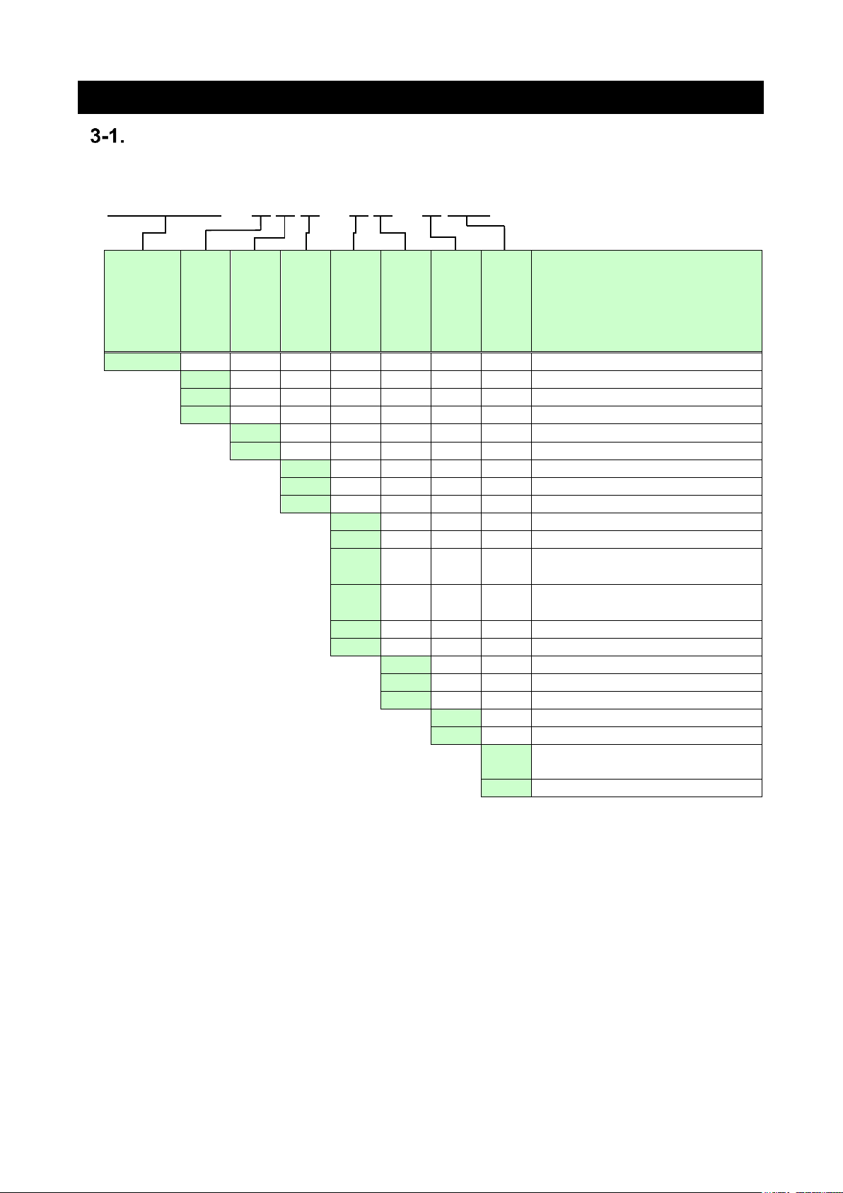
3. BEFORE USING THE PRODUCT
MODEL CODES
The model code of this product is shown as below. Check the product which has been delivered has a
same model code you ordered.
WPMZ-3-□□□-□□-□□□
Series name
Supply
power
Input A
Input B
Output
Comparative
output
Test report
Additional
code
Description
WPMZ-3
Straingauge meter
1 Supply power : AC100 to 240V
3 Supply power : DC12V
4 Supply power : DC24 to 48V
S Straingauge input
B Process input
X
No Bch input
S
Straingauge input
B
Process input
X Display only (No output)
1 Analog output
2
BCD output
(open collector NPN)
3
BCD output
(open collector PNP)
4 RS-232C
5 RS-485 Modbus RTU
E Open collector NPN
F Open collector PNP
R Relay output (Normally open)
X Without test report
T With test report
00
Standard
(Initial language:Japanese)
E0
Initial language setting: English
Graphical Digital Panel Meter WPMZ-3 INSTRUCTION MANUAL
12
IM-0883-01
4. MOUNTING METHOD
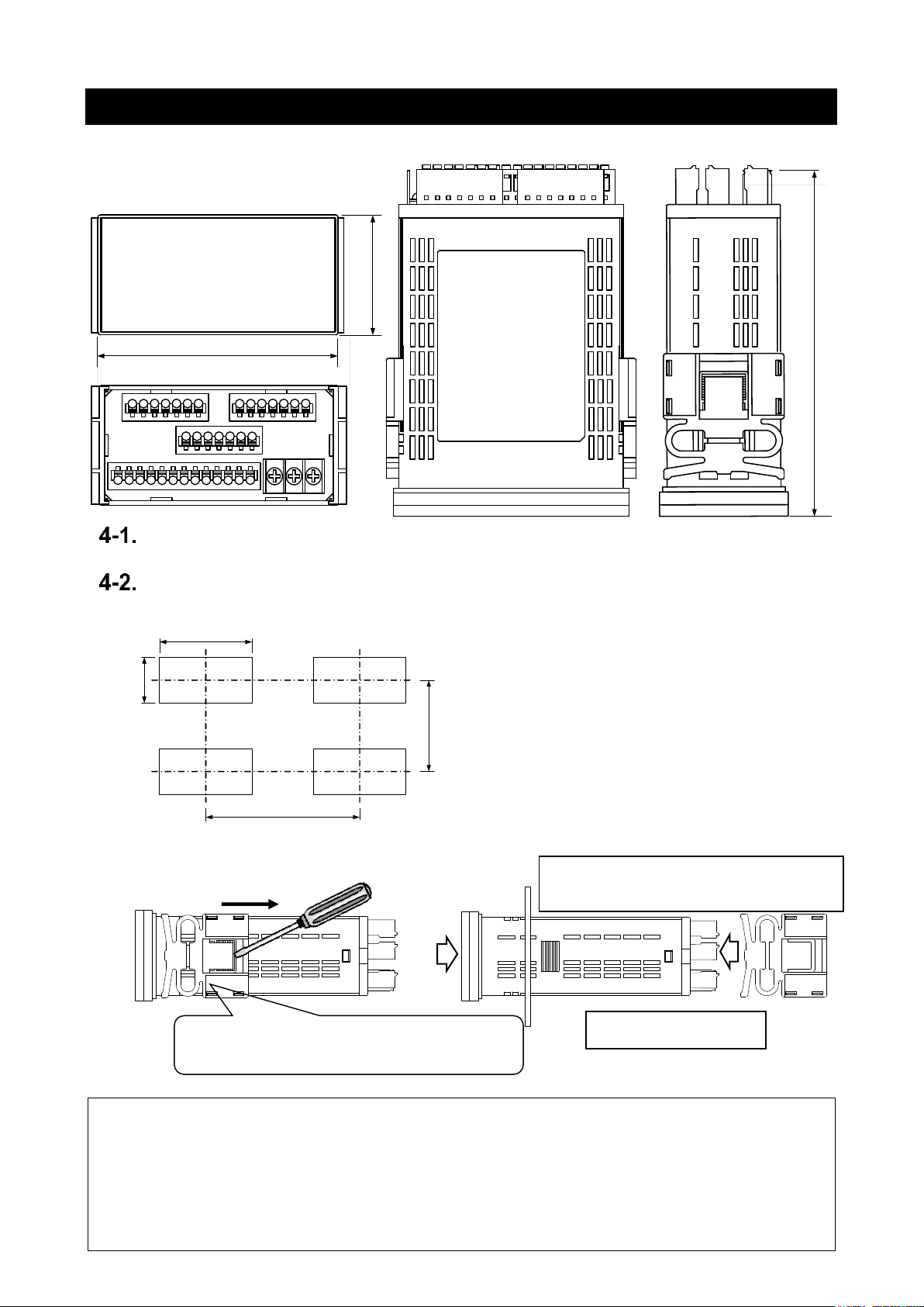
EXTERNAL FORM DIMENSIONS
PANEL MOUNTING METHOD
Panel cut dimensions are as shown by the figure below.
1) Removal of case fixing attachments 2) Installment of case fixing attachments
CAUTION
○ Prior to the installation of this product please read “1-1. ENVIRONMENTS AND CONDITIONS
OF USE” (page8)
○ In the case of installation or replacing of this product, please pay attention to the damage and
accident by dropping.
○ In the case of some wires are connected, do not install or replacing this product. It may cause shock,
damage fire etc.
Slide the attachment to the direction of arrow with
lifting the clicks of the lock lever by a flat-blade
screwdriver etc and remove it.
① Insert the body into the
panel from the front side.
②Insert the case fixing attachments from back
side at both left and right sides and hold the
panel between the body and them.
96
52
145
Recommended panel thickness : 0.8 to 5mm
+0.8
92
+0.6
-0
MIN 120
MIN 70
45
-0
Graphical Digital Panel Meter WPMZ-3 INSTRUCTION MANUAL
13
IM-0883-01
5. CONNECTING TERMINALS
WIRING TO TERMINALS
The connections to this product are done by connecting wires to the screw terminal block (power
supply) and screwless terminal blocks on the back side of the body. Show below for the method and
precautions.
CONNECTING TERMINALS
Use crimp-type terminal lugs for M3 screws to connect the terminals.
① Loosen the screws of the terminal block.
In the case of R-type terminal lugs, remove the screw terminals
from the terminal block.
②Insert lugs under the washers of loosened screws and fasten the screws.
(Recommended torque:0.6 [N・m])
WIRING TO SCREWLESS TERMINALS
① Pushing the wire release button with a flat-blade screwdriver, open the wire insert hole.
(Flat-blade screwdriver : The point of a blade width 2.5mm)
② Wire is inserted in an expanded wire insertion hole and a flat-blade screwdriver is removed.
(Suitable wire:AWG24 to 16)
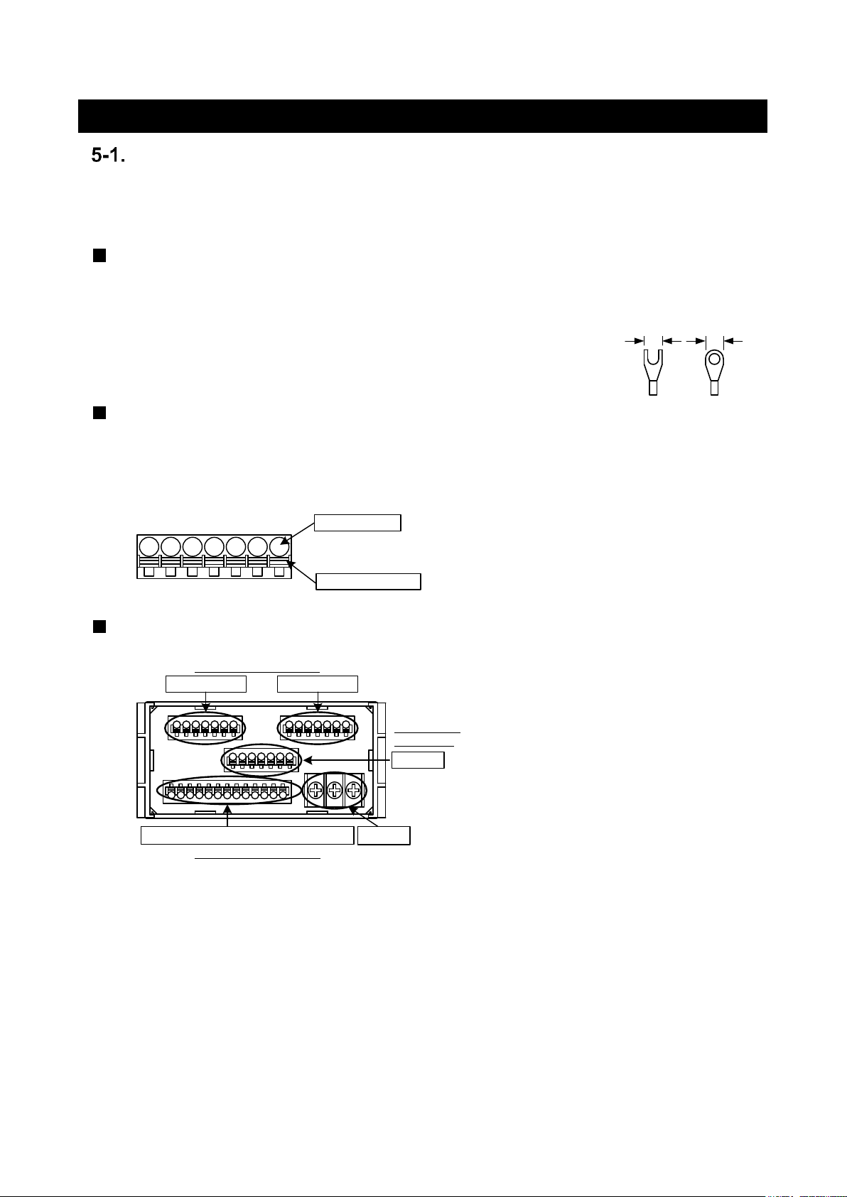
THE LOCATION OF EACH TERMINAL STAND
Note: In this manual, “channel A”, “channel B” may be abbreviated to “chA”,”chB” (or “Ach”,”Bch”).
5.8max.
Suitable crimping
terminal
5.8max.
Wire insert hole
Wire release button
Ach inputs Bch inputs
Power
Comparetive output/External control input
outputs
UPPER ROW TERMINALS
MIDDLE ROW
TERMINALS
LOWER ROW TERMINALS

Graphical Digital Panel Meter WPMZ-3 INSTRUCTION MANUAL
14
IM-0883-01
CONNECTION FOR LOWER ROW TERMINALS
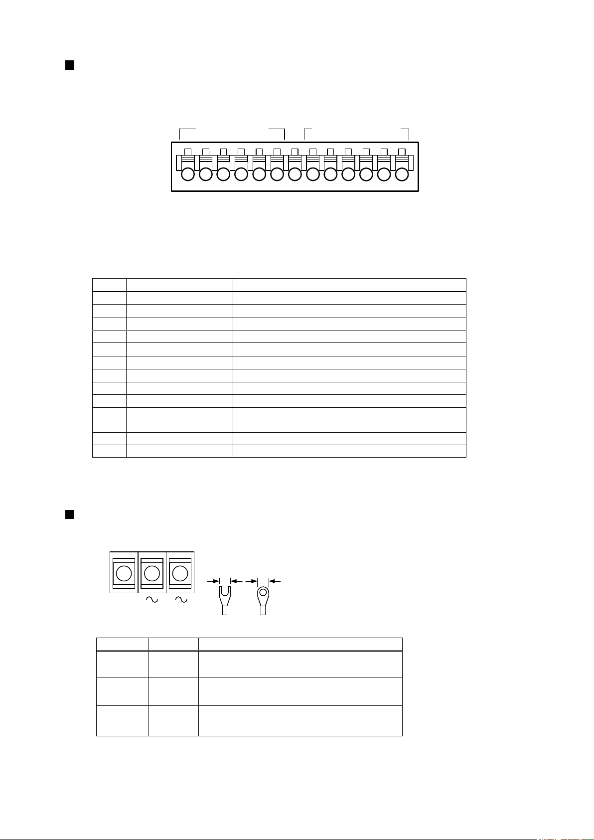
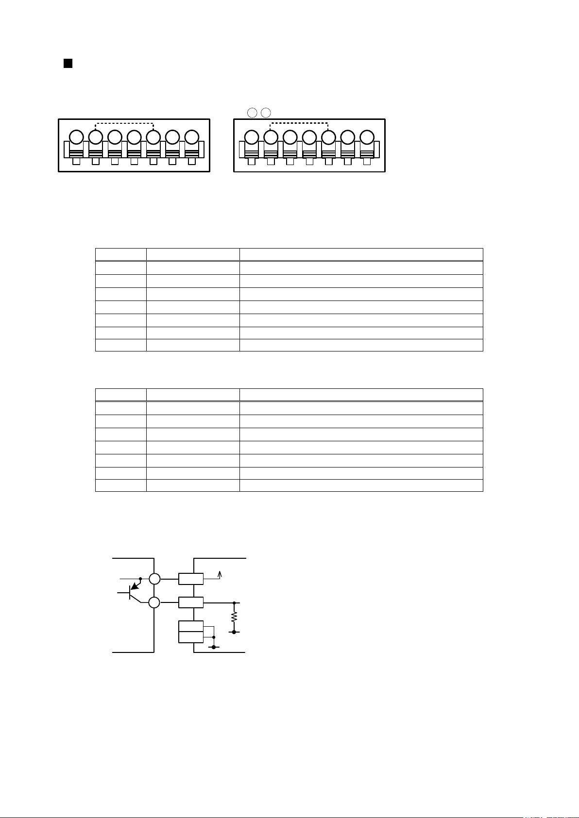
COMPARETIVE OUTPUT(O.C.)/EXTERNAL CONTROL INPUT
Screwless terminals
No.
Name
Description
1
AL1 c
AL1 open-collector output (collector)
2
AL2 c
AL2 open-collector output (collector)
3
AL3 c
AL3 open-collector output (collector)
4
AL4 c
AL4 open-collector output (collector)
5
AL+COM e
Common terminal for PNP output (emitter)
(NPN output : no connection)
6
AL-COM e
Common terminal for NPN output (emitter)
(PNP output : GND for PNP)
7,8
COM
Common terminal for external control inputs
9
EXT CONTROL 1
External control input No.1
10
EXT CONTROL 2
External control input No.2
11
EXT CONTROL 3
External control input No.3
12
EXT CONTROL 4
External control input No.4
13
EXT CONTROL 5
External control input No.5
*1 “AL-COM e terminal” and “COM terminal” is connected internally and same voltage level.
AL2
COM
AL1
Suitable wire:AWG 24 to16
AL4
AL3
COM
AL +COM
AL -COM
1 2 3 4 5 6 7 8 9
10
11 12 13
※⑥、⑦、⑧ : connected internally
EXT 1
EXT 2
EXT 3
EXT 4
EXT 5
External control inputsOpen collector outputs
Graphical Digital Panel Meter WPMZ-3 INSTRUCTION MANUAL
15
IM-0883-01
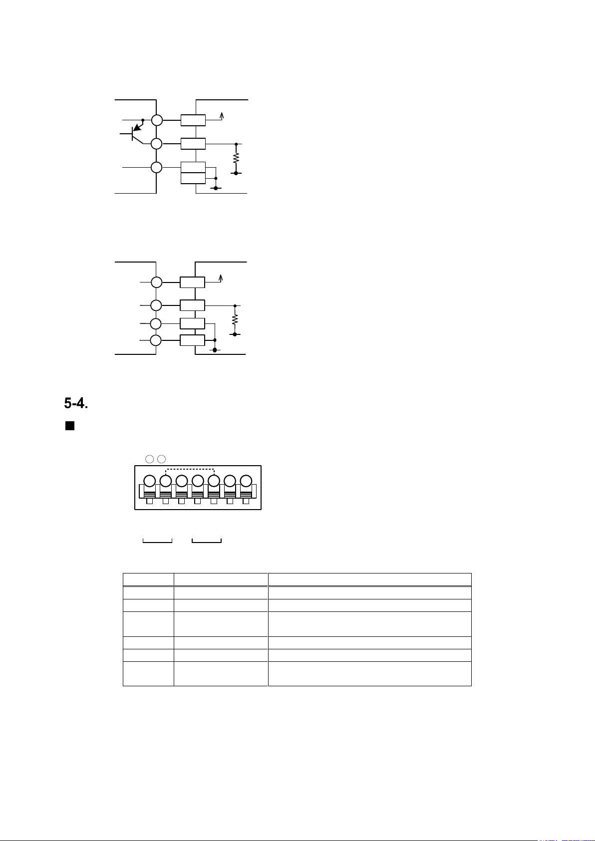
COMPARETIVE OUTPUT(relay)/EXTERNAL CONTROL INPUT
Screwless terminals
No.
Name
Description
1
AL1
AL1 relay output
2
AL1・2 COM
Common terminal for outputs of AL1 and AL2
3
AL2
AL2 relay output
4
AL3
AL3 relay output
5
AL3・4 COM
Common terminal for outputs of AL3 and AL4
6
AL4
AL4 relay output
7 × N.C. *1
8
COM
Common terminal for external control inputs
9
EXT CONTROL 1
External control input No.1
10
EXT CONTROL 2
External control input No.2
11
EXT CONTROL 3
External control input No.3
12
EXT CONTROL 4
External control input No.4
13
EXT CONTROL 5
External control input No.5
*1 Please do not wire to N.C. terminal.
SUPPLY POWER
Screw terminals
Terminal
Name
Description
P1
POWER
(+)
Power source terminal
(In case of DC power, +V)
P2
POWER
(-)
Power source terminal
(In case of DC Power, 0V)
P3
FG
(NC)
FG terminal
(DC power option: no connection
( *Non-usable for a relay terminal))
(Recommended torque: 0.6 [N・m])
AL1・2 COM
COM
AL1
Suitable wire:AWG 24 to 16
AL3
AL2
×
AL3・4 COM
AL4
1 2 3 4 5 6 7 8 9
10
11 12 13
EXT 1
EXT 2
EXT 3
EXT 4
EXT 5
External control inputsRelay outputs
POWER
FG
(-) (+)
P2 P1
5.8max.
Suitable crimping
terminal
5.8max.
P3
(NC)
( ):DC POWER
Graphical Digital Panel Meter WPMZ-3 INSTRUCTION MANUAL
16
IM-0883-01
CONNECTION FOR UPPER ROW TERMINALS
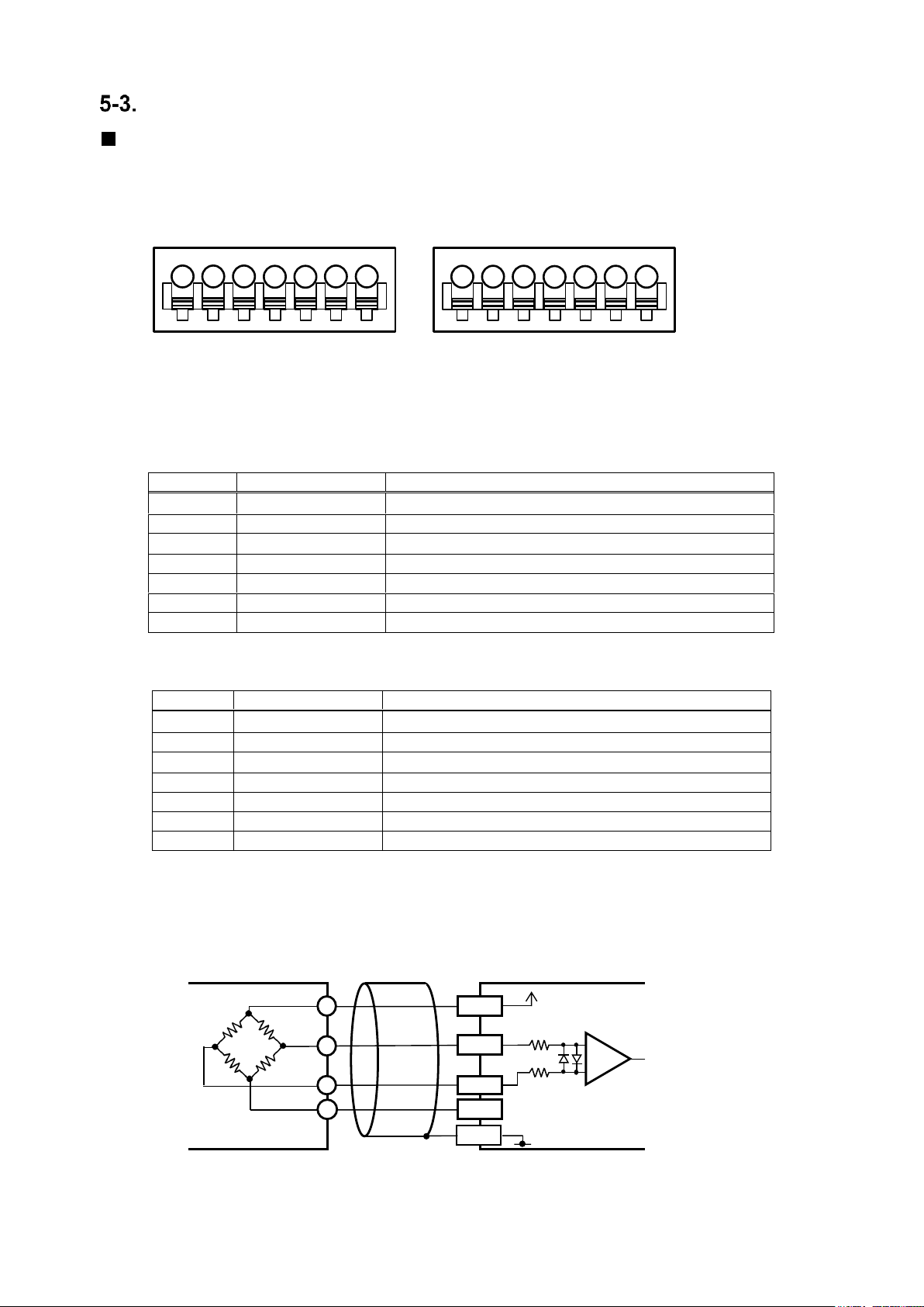
STRAINGAUGE INPUTS
Screwless terminals
●Ach Straingauge input/GO output
No.
Name
Description
14
+EXC
Ach bridge power output terminal(+)
15
-SIG
Ach input (-) terminal
16
-EXC
Ach bridge power output terminal(-)
17
+SIG
Ach input (+) terminal
18
GND
Ach ground terminal
19
GO.OUT
Ach GO output terminal(collector)
20
GO.GND
Ach GO output terminal(emitter)
* When bridge power supply is 5V or 2.5V, -EXC and GND are connected internally.
●Bch Straingauge input/GO output
No.
Name
Description
21
+EXC
Bch bridge power output terminal(+)
22
-SIG
Bch input (-) terminal
23
-EXC
Bch bridge power output terminal(-)
24
+SIG
Bch input (+) terminal
25
GND
Bch ground terminal
26
GO.OUT
Bch GO output terminal(collector)
27
GO.GND
Bch GO output terminal(emitter)
* When bridge power supply is 5V or 2.5V, -EXC and GND are connected internally.
●Example for input connections
+EXC
-SIG
+SIG
GND
Ach Straingauge input
Suitable wire:AWG 24 to 16
-EXC
+EXC
-SIG
+SIG
GND
Bch Straingauge input
Suitable wire:AWG 24 to 16
-EXC
20
14 15 16
17
18
19
27
21 22 23
24
25
26
GO.OUT
GO.GND
GO.OUT
GO.GND
+EXC
-EXC
+SIG
-SIG
GND
+IN
-IN
+OUT
-OUT
Bridge circuit
WPMZ-3
Straingauge input
10V
(5V)
(2.5V)
Graphical Digital Panel Meter WPMZ-3 INSTRUCTION MANUAL
17
IM-0883-01
PROCESS INPUTS
Screwless terminals
●Ach Process input/GO output
No.
Name
Description
14
V HI
Ach voltage input terminal(+)
15
LO
Ach common input terminal(-)
16
A HI
Ach current input terminal(+)
17
+EXC
Ach sensor power output terminal(+)
18
-EXC
Ach sensor power output terminal(-)
19
GO.OUT
Ach GO output terminal(collector)
20
GO.GND
Ach GO output terminal(emitter)
*1 “LO terminal” and “-EXC terminal” is connected internally and same voltage level.
●Bch Process input/GO output
No.
Name
Description
21
V HI
Bch voltage input terminal(+)
22
LO
Bch common input terminal(-)
23
A HI
Bch current input terminal(+)
24
+EXC
Bch sensor power output terminal(+)
25
-EXC
Bch sensor power output terminal(-)
26
GO.OUT
Bch GO output terminal(collector)
27
GO.GND
Bch GO output terminal(emitter)
*1 “LO terminal” and “-EXC terminal” is connected internally and same voltage level.
●Example of connecting to sensor(2 wire type sensor)
+12V (+24V)
LO
-EXC
+EXC
HI
VCC
2 wire type sensor
WPMZ-3
Input: Process
* Use [V HI] terminal as HI terminal if the sensor
is voltage output type, use [A HI] terminal if
the sensor is current output type.
+
-
Ach Process input
Suitable wire:AWG 24 to 16
GO.OUT
GO.GND
V HI
LO
+EXC
-EXC
A HI
Bch Process input
Suitable wire:AWG 24 to 16
GO.OUT
GO.GND
V HI
LO
+EXC
-EXC
A HI
20
14 15 16
17
18
19
27
21 22 23
24
25
26
※⑮、⑱ : connected internally ※ 、 : connected internally
22 25
Graphical Digital Panel Meter WPMZ-3 INSTRUCTION MANUAL
18
IM-0883-01
●Example of connecting to sensor(3 wire type sensor)
+12V (+24V)
LO
-EXC
+EXC
HI
VCC
GND
3 wire type sensor
WPMZ-3
Input: Process
* Use [V HI] terminal as HI terminal if the sensor
is voltage output type, use [A HI] terminal if
the sensor is current output type.
●Example of connecting to sensor(4 wire type sensor)
+12V (+24V)
LO
-EXC
+EXC
HI
VCC
GND
4 wire type sensor
WPMZ-3
Input: Process
* Use [V HI] terminal as HI terminal if the sensor
is voltage output type, use [A HI] terminal if
the sensor is current output type.
+OUT
-OUT
CONNECTION FOR MIDDLE ROW TERMINALS
ANALOG OUTPUT
Screwless terminals
No.
Name
Description
28
V.OUT
Analog voltage output terminal (+)
29
V.COM
Analog voltage output terminal (-)
30
NC
No connection
*Non-usable for a relay terminal
31
A.OUT
Analog current output terminal (+)
32
A.COM
Analog current output terminal (-)
33,34
NC
No connection
*Non-usable for a relay terminal
*1 “V.COM terminal” and “A.COM terminal” is connected internally and same voltage level.
V.OUT
V.COM
NC
A.OUT
A.COM
NC
NC
34
28 29
30
31
32
33
* 、 :connected internally
29 32
Voltage output Current output
Suitable wire:AWG24 to 16
Graphical Digital Panel Meter WPMZ-3 INSTRUCTION MANUAL
19
IM-0883-01
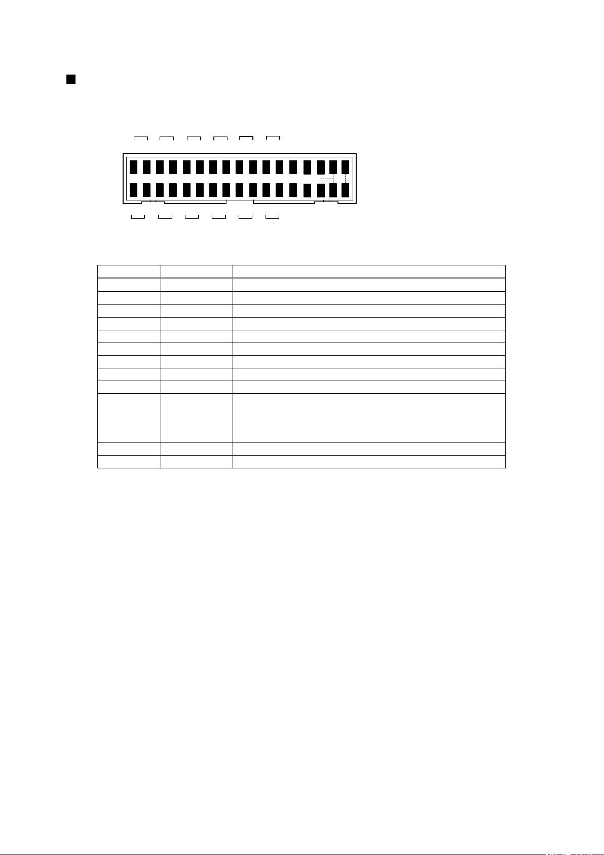
BCD OUTPUT
Crimp connector
No.
Name
Description
1 to 4
1001-8
Bit 1-8 of BCD 100 digit output terminals
5 to 8
1011-8
Bit 1-8 of BCD 101 digit output terminals
9 to 12
1021-8
Bit 1-8 of BCD 102 digit output terminals
13 to 16
1031-8
Bit 1-8 of BCD 103 digit output terminals
17 to 20
1041-8
Bit 1-8 of BCD 104 digit output terminals
21 to 24
1051-8
Bit 1-8 of BCD 105 digit output terminals
25
POL
BCD polarity output terminal
26
OVER
BCD over output terminal
27
PC
BCD synchronous signal output terminal
28
ENABLE
BCD enable terminal
By bringing to same voltage level of -D.COM or
connecting to –D.COM, transistors of BCD outputs
become OFF.
29 to 32
-D.COM
Common terminal for BCD open collector NPN
33,34
+D.COM
External power terminal for BCD open collector PNP
ENABLE
34
33
-D.COM
OVER
2
1
10
2 8 2 8
2 8 2 8
1 4 1 4 1 4 1 4
0
10110210
3
10010110210
3
-D.COM
PC
POL
1 4
10
4
2 8
10
4
-D.COM
+D.COM
(PNP)
-D.COM
+D.COM
(PNP)
Suitable wire:AWG#28 flat cable(7/0.127mm)
2 8
10
5
1 4
10
5

Graphical Digital Panel Meter WPMZ-3 INSTRUCTION MANUAL
20
IM-0883-01
RS-232C
Screwless terminals
No.
Name
Description
28
RXD
Receive data terminal
29
TXD
Transmit data terminal
30
SG
Common terminal for communication function
31 to 34
NC
No connection
*Non-usable for a relay terminal
RS-485 MODBUS RTU
Screwless terminals
No.
Name
Description
28
+
Non-inverting signal
29
-
Inverting signal
30
SG
Signal ground
31
+
Non-inverting signal
32
-
Inverting signal
33,34
TERM
Terminal resistance (120Ω)terminals
* Short 33 and 34 to be enable the resistance.
* “28 terminal” and “31 terminal” is connected internally and same voltage level.
* “29 terminal” and “32 terminal” is connected internally and same voltage level.
RXD
TXD
SG
NC
NC
NC
NC
34
28 29 30
31
32
33
Suitable wire:AWG24 to 16
+
RS-485
TERM
TERM
SG
-
+
RS-485
-
34
28 29
30
31
32
33
* 、 & 、 :connected internally
28 31
29 32
Suitable wire:AWG24 to 16
Graphical Digital Panel Meter WPMZ-3 INSTRUCTION MANUAL
21
IM-0883-01
6. NAMES OF EACH PART
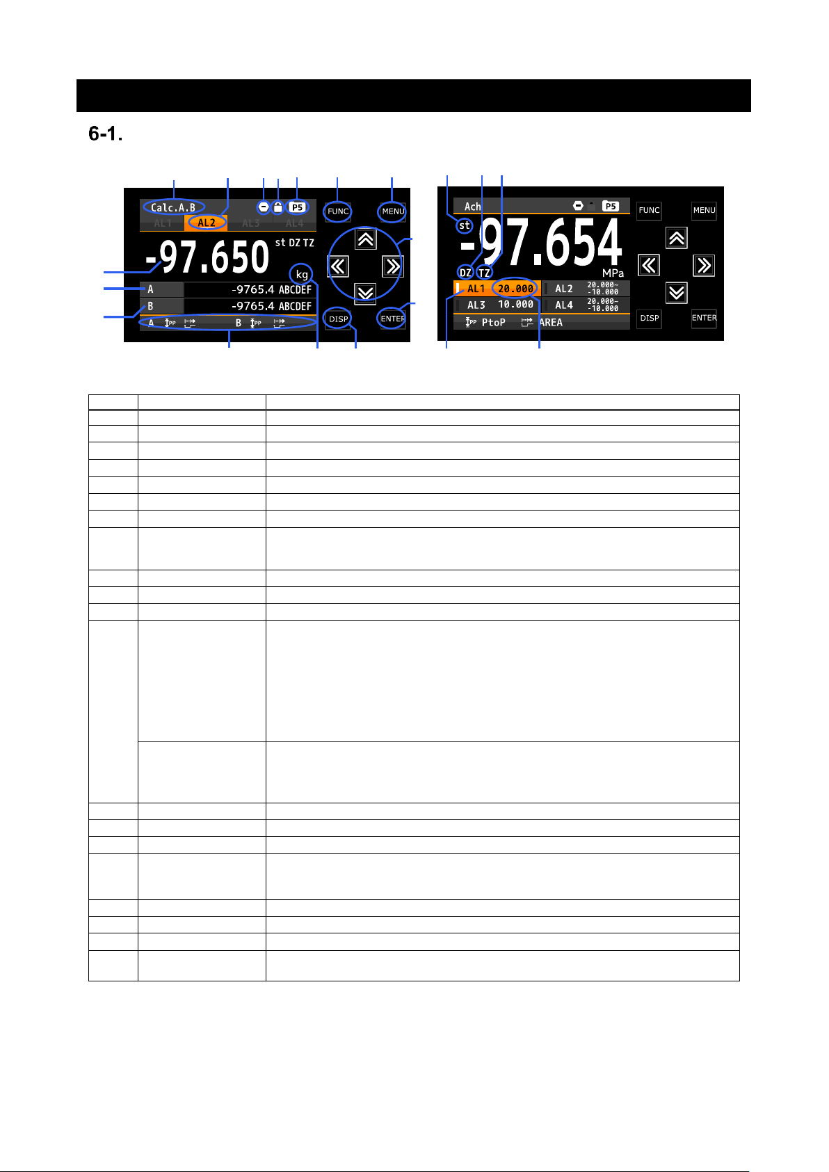
NAMES OF EACH PART
No.
Name
Function
①
Display title
Indicates contents of display
②
Comparison result
Lights when the result of comparative output is ON.
③
Compare reset
Lights when the “CompareReset”function is ON.
④
Key lock
Lights when the key lock is effective.
⑤
Pattern
Indicates pattern No. in use.
⑥
FUNC key
Used for registering external control shortcut function.
⑦
MENU key
Used for moving to setting display and returning measurement display.
⑧
Arrow keys
Used to move the cursor while setting and move other displays.
*When the shortcut function is registered, the assigned function will be valid by
holding down the arrow key (over 1 second).
⑨
ENTER key
Used to validate setting value.
⑩
DISP key
Used to switch measurement displays.
⑪
Display unit
Unit for 1st item display
⑫
Hold type
Indecate hold type by an icon.
* For 1ch input products, the following abbreviations will be added.
HOLD: DispHold
MAX: MaxHold
MIN: MinHold
PtoP: AmpHold
DIFF: DevHold
AVE: AveHold
Hold mode
Indecate hold mode with icon.
* For 1ch input products, the following abbreviations will be added.
NORM: NormalHold
AREA: AreaHold
⑬
3rd item display
Displays measured value of 3rd item
⑭
2nd item display
Displays measured value of 2nd item
⑮
1st item display
Displays measured value of 1st item
⑯
st icon
Lights up during display value is stable.
(Only when the “ActCondition” function is OnStable or
OnStableExceptNearZero)
⑰
DZ icon
Lights up during digital zero operation.
⑱
TZ icon
Lights up during tracking zero operation.
⑲
Comparison result
Lights when the result of comparative output is ON.
⑳
Comparison
judgement value
Displays comparison judgement value.
⑲
⑳
①
②
③④
⑤ ⑥
⑦
⑧
⑨
⑩
⑪
⑫
⑮
⑭
⑬
⑯
⑰ ⑱

Graphical Digital Panel Meter WPMZ-3 INSTRUCTION MANUAL
22
IM-0883-01
EXPLANATION OF ICONS
DISPLAY ICONS ON THE MEASUREMENT DISPLAY
Icon
Meanings
Icon
Meanings
Indicates comparative output reset
function is effective.
HoldMode/DispHoldMode is
NormalHold/Normal.
Indicates DispHold function is
effective.
HoldMode/DispHoldMode is
AreaHold/Normal.
Indicates MaxHold function is
effective.
DispHoldMode is OneShot.
Indicates MinHold function is
effective.
Indicates digital zero operation is
effective.
Indicates AmpHold function is
effective.
Indicates pattern No. in use.
Indicates DevHold function is
effective.
Indicates key lock function is
effective.
Indicates AveHold function is
effective.
* There are specific icons for multi hold mode, but they are not mentioned above. Please see the chapter
on multi hold mode.
KEY OPERATION ICONS ON THE SETTING DISPLAY
Icon
Meanings
Icon
Meanings
MENU
key
Arrow key
(LEFT)
FUNC
key
Arrow key
(RIGHT)
ENTER
key
Arrow key
(UP&DOWN)
DISP key
Arrow key
(LEFT&RIGHT)
Arrow
key (UP)
Arrow key
(ALL)
Arrow
key
(DOWN)
Pattern No.
under setting
Graphical Digital Panel Meter WPMZ-3 INSTRUCTION MANUAL
IM-0883-01
7. MODES OF OPERATION
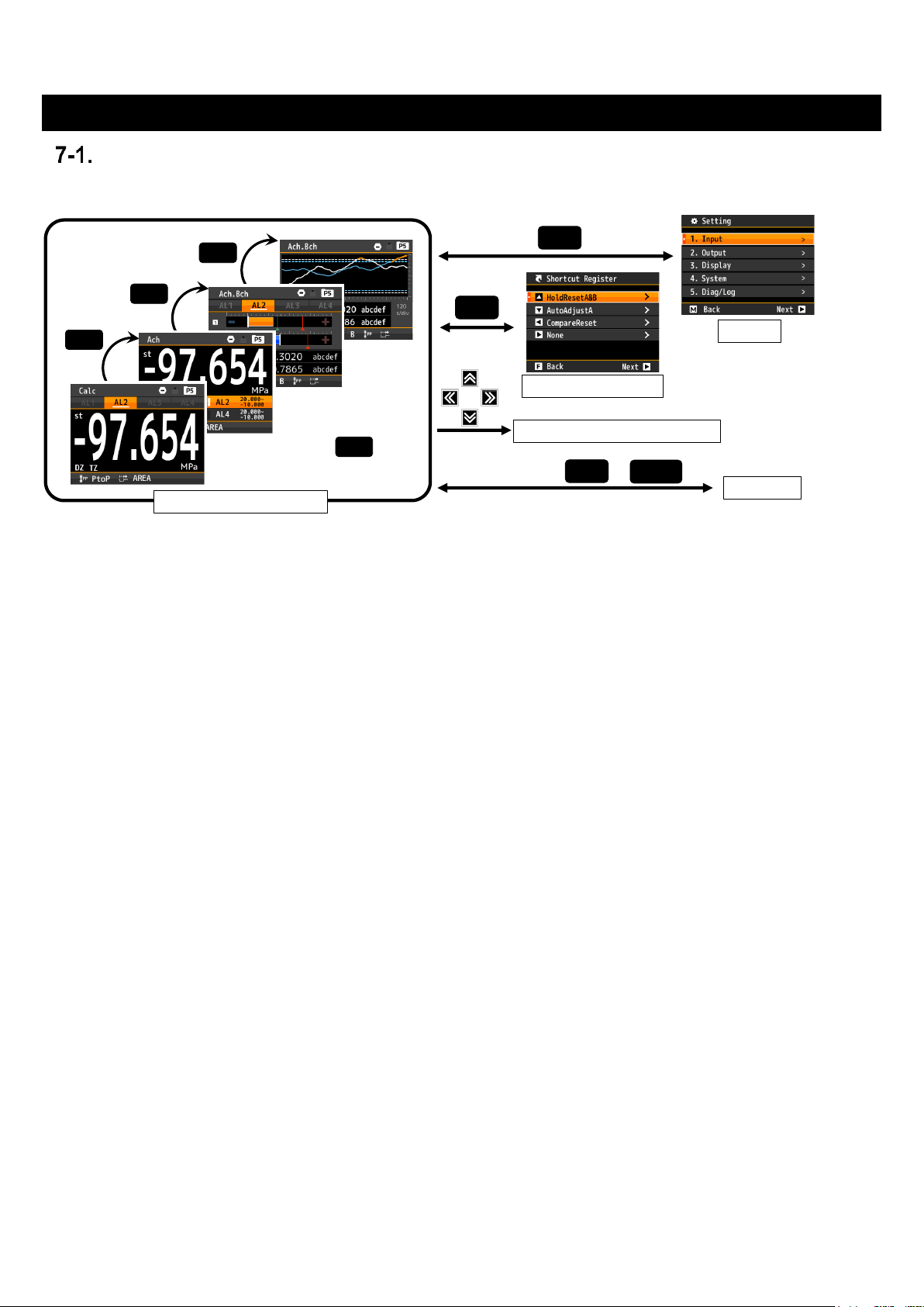
OPERATION ON MEASUREMENT DISPLAY
The system starts up after power on, and works as shown below.
【Measurement Display】
By pressing the DISP key, each measurement display including level display, and trend display is displayed
in order.
The measurement displays to be displayed can be selected by "screen setting".
【Setting】
You can make various settings.
Press the "MENU" key to open the setting screen and press the "MENU" key again to return to the
measurement display.
【Shortcut Register】
Register the shortcut function.
Press the "FUNC" key to open the Shortcut Register screen and press the "FUNC" key again to
return to the measurement display.
You can register up to 4 from external control functions, “ManuAdjust”, and “AutoAdjust”.
【Perform Shortcut Register】
By holding down any of the four-way controller keys for 1sec, the shortcut function will be done.
* Shortcuts will not work if the same function is done via communication control or external control.
【Key Lock】
By holding down both “DISP” and “ENTER” keys for 1sec, the key lock function will be done.
If the key lock function is doing, the system will not accept any key operations except key lock.
* Since the measurement screen will change if the "DISP" key is pressed first,
you should first press the "ENTER" key and then press the "DISP" key.
DISP
DISP
MENU
FUNC
Setting
DISP
Shortcut Register
Measurement Display
Perform Shortcut function
Key Lock
DISP
ENTER
Holding down for 1sec
+
DISP
Holding down
for 1sec
Graphical Digital Panel Meter WPMZ-3 INSTRUCTION MANUAL
24
IM-0883-01
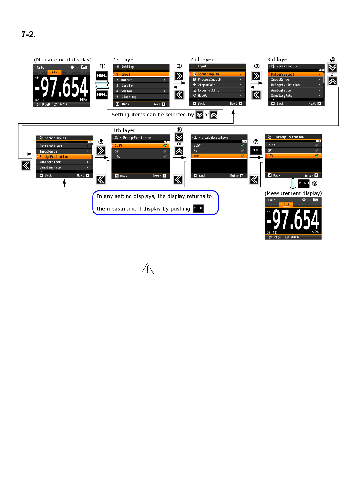
OPERATION ON SETTING
The setting procedure is shown below.
*Some setting value change numerical value or other value.
CAUTION
The timing at which the change of the set value is saved is the point when returning
to the measurement screen from the setting screen.
Please keep in mind that setting change will not be saved if you turn off the power
during setting screen.
Graphical Digital Panel Meter WPMZ-3 INSTRUCTION MANUAL
25
IM-0883-01
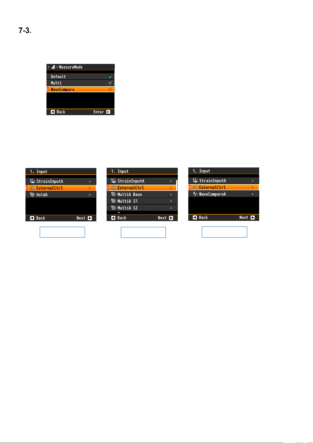
MEASUREMENT MODE SWITCHING
This system has “Multi Hold mode” and “Wave Compare mode” besides “Default mode”.
“Multi Hold mode” and “Wave Compare mode” are input signal judgment function.
These modes are switched in “MeasureMode”. ( [Setting]⇒[System]⇒[General]⇒[MeasureMode] )
The input setting changes to a dedicate one for each mode after switching measurement mode.
Please check a table on next page that shows correspondence of each mode and function.
INPUT SETTING DISPLAYS ON EACH MEASUREMENT MODE
【Multi Hold】
Hold the inflection point and maximum / minimum points in the caulking process etc. for each specified
section and make a judgment. Up to 4 sections can be specified for the section, and the judgment value can be
set for each hold value.
For details, see the chapter for “Multi Hold mode”.
【Wave Compare】
Input signal such as press fitting process is taken in as a waveform, and comparison judgment is carried out
using judgment waveform. Unlike comparative judgment with a single value, good / bad judgment can be
made for the whole process.
For details, see the chapter for “Wave Compare mode”.
*Please set “DispSelect” again after switching measurement mode. ( [Setting]⇒[Display]⇒[DispSelect] )
* The factory setting is "Default mode”.
* Only one can be activated.
Default
Wave Compare
Muluti Hold

Graphical Digital Panel Meter WPMZ-3 INSTRUCTION MANUAL
26
IM-0883-01
CORRESPONDENCE OF EACH MODE AND FUNCTION
If you change measurement mode, settings of enable/disable of each functions switch automatically and disabled
functions are disappeared. Correspondence table of each mode and function is below.
* You cannot change settings of disabled function by communication. (RS-485 and RS-232C)
Functions
Default
mode
Wave
Compare
mode
Multi
Hold
mode
Input
Straingauge input
〇 〇 〇
Processs input
〇 〇 〇
2 input calc
〇 × ×
External controls except controls
related to hold
〇 〇 〇
Hold functions
Normal hold function
〇 × ×
Multi hold function
× × 〇
Output
Analog output
〇 〇 〇
BCD output
〇 〇 〇
RS-485 communication
〇 〇 〇
RS232C communication
〇 〇 〇
Normal compare output
〇 × ×
Wave compare output
× 〇 ×
Section comparison function in
multi hold mode
× × 〇
Display
1 item dislpay/2 items display
〇 〇 〇
1 item display with comparison
judgement value
〇 × ×
3 items display
〇 × ×
Level display
〇 × ×
Trend display
〇 × ×
Wave compare display
×
〇
×
Multi hold display
× × 〇
Log
Alarm log functnion
〇 × ×
Wave log function
× 〇 ×
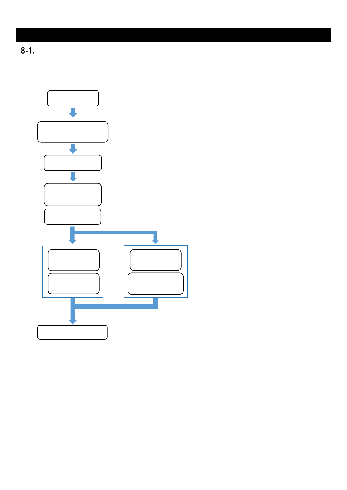
Graphical Digital Panel Meter WPMZ-3 INSTRUCTION MANUAL
27
IM-0883-01
8. BESIC SETTINGS
CALIBRATION OF STRAINGAUGE INPUT
Calibration of straingeage input is proceed as follow.
Each setting items are set up at [Setting]⇒[Input]⇒[StrainInputA] or [StrainInputB].
When registering calibration values of multiple sensors, change the pattern and continue setting and
calibration.
Descriptions of each setting item are described on the following pages after this section.
Moreover, please check "input detailed setting" for the setting not described in the above flow.
*1 Each setting and calibration value are saved and reflected at the timing when the menu is closed and
returned to the measurement screen.
Note that the contents will not be saved if the power is turned off before closing the menu.
Pattern select
Bridge power supply
voltage select
Zero point
adjustment
Actual load
calibration
Equivalent
load calibration
Zero point
adjustment
Decimal point
position select
Unit select
Measurement start
*If you changed the bridge power supply, please
close the menu once for reflecting the setting.
Connect a sensor
*When actual loading to the sensor is possible,
please perform "Actual load calibration", and is
inpossible, please perform "Equivalent load
calibration".
"Zero point adjustment" is performed within
each calibration setting item.
*For wiring, please confirm
"5. CONNECTING TERMINALS”.
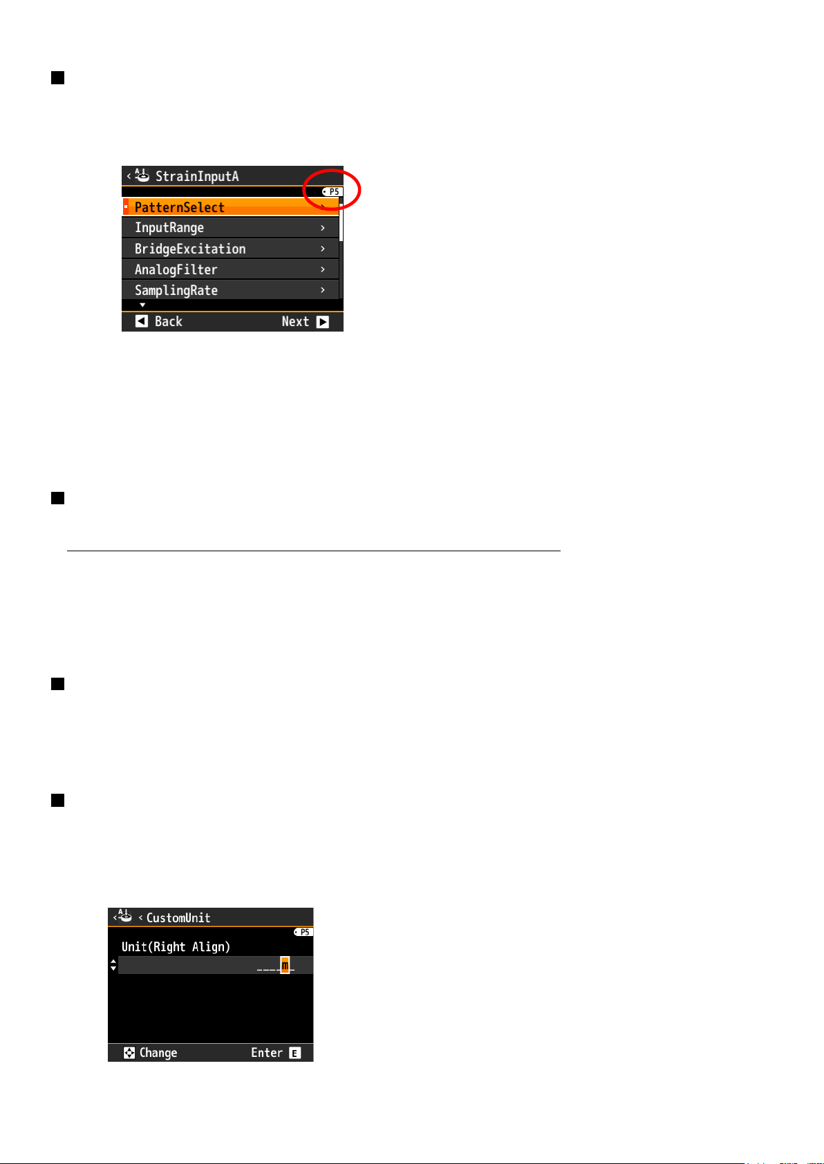
Graphical Digital Panel Meter WPMZ-3 INSTRUCTION MANUAL
28
IM-0883-01
PatternSelect
You can store and set up 8 patterns (8 kinds) of various settings such as input and output with this unit, you can
select the pattern to save the setting in "PatternSelect".
The pattern number being set is displayed as "P5" on the upper right of the setting screen as shown below.
Operation:[MENU]⇒[Input]⇒[StrainInputA][StrainInputB]⇒[PatternSelect]
Setting value:Pattern1,Pattern 2,・・・・・Pattern 8
*At the time of opening the menu, the setting pattern is the value selected as operating on the measurement
screen.
* Since the setting pattern is common in each setting, "PatternSelect" such as output setting is also changed
when "PatternSelect" is changed by "StrainInput A" or "StrainInput B".
BridgeExcitation
Select bridge power supply voltage for sensor.
Please close the menu once for reflecting the setting before connect a sensor.
Operation:[MENU]⇒[Input]⇒[StrainInputA][StrainInputB]⇒[BridgeExcitation]
Setting value:2.5V,5V(Default),10V
*The maximum supply current is 30mA@2.5V, 60mA@5V, 30mA@10V
DecPoint
Select decimal point position of display value.
Operation:[MENU]⇒[Input]⇒[StrainInputA][StrainInputB]⇒[DecPoint]
Setting value:##### (Default),####.#,###.##,##.###,#.####
DispUnit
Select a unit for display value.
Operation:[MENU]⇒[Input]⇒[StrainInputA][StrainInputB]⇒[DispUnit]
Setting value:μm,mm,cm,m,inch,g,kg,t,N,kN,MN,mN・m,N・m,kN・m,Pa,kPa,MPa,hPa,
kg/m2,N/m2,CustomUnit
*If you select “CustomUnit”, you can create an original
unit within 6 letters. You can use following letters to
create a unit. ([a]~[z], [A]~[Z],
[,],(,),1,2,3,1,2,3,-,μ,Ω,g,・,/,ℓ,%,%0,°,’,” )
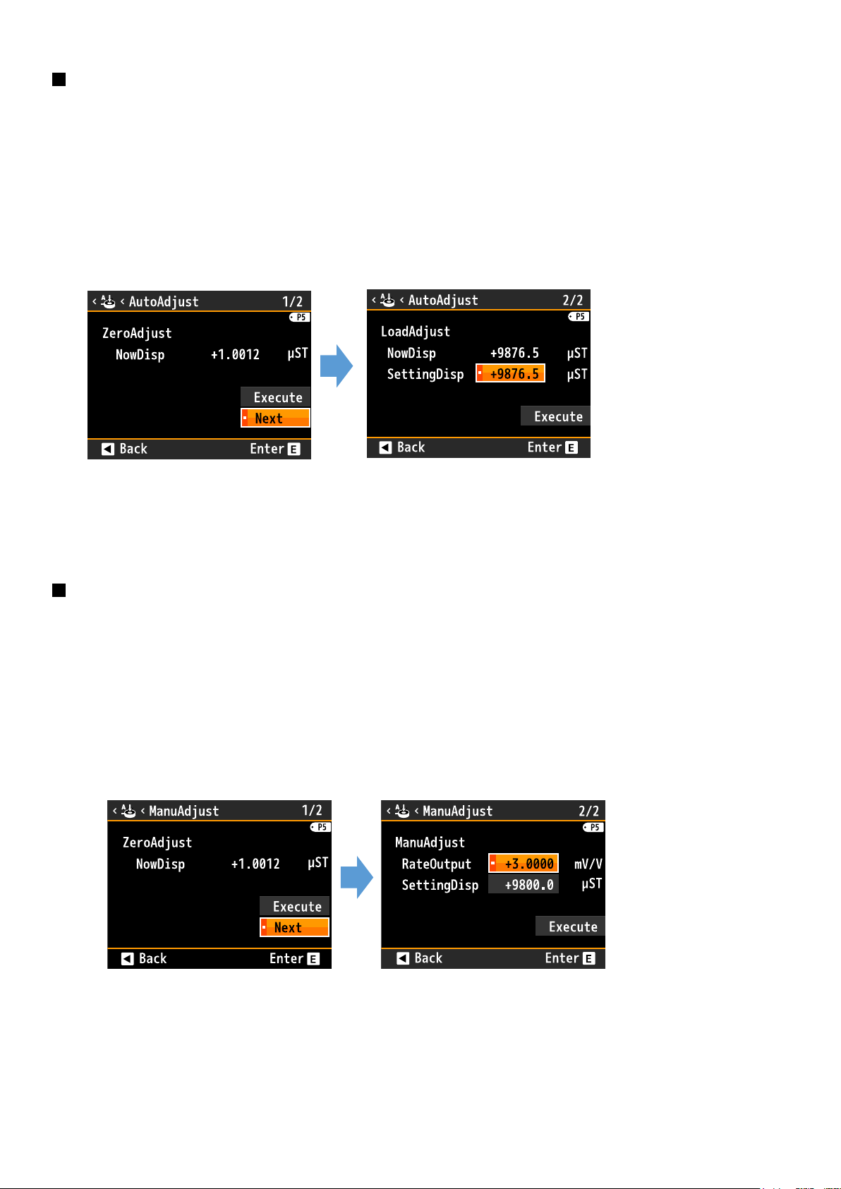
Graphical Digital Panel Meter WPMZ-3 INSTRUCTION MANUAL
29
IM-0883-01
AutoAdjust
Do actual load calibration.
As shown in the figure below, it has 2 screen configurations, and "Zero point calibration" "Actual load
calibration" is continued and executed.
●Operation for calibration
1. Connect the sensor and set it to no load condition.
2. Select "Execute" and press "ENTER" key.
3. Select "Next" and press "ENTER" key.
4. Apply actual load to the sensor.
5. Set the input load value to "SetValue".
6. Select "Execute" and press "ENTER" key.
Operation:[MENU]⇒[Input]⇒[StrainInputA][StrainInputB]⇒[AutoAdjust]
Setting value:-99999~99999 (SetValue)
*Setting values of “DecPoint” and “DispUnit” are reflected.
ManuAdjust
Do equivalent load calibration.
As shown in the figure below, it has 2 screen configurations, and "Zero point calibration" "Equivalent load
calibration" is continued and executed.
●Operation for calibration
1. Connect the sensor and set it to no load condition.
2. Select "Execute" and press "ENTER" key.
3. Select "Next" and press "ENTER" key.
4. Set rated output value of sensor to “Rating”.
5. Set rated capacity value of sensor to “SetValue”.
6. Select "Execute" and press "ENTER" key.
Operation:[MENU]⇒[Input]⇒[StrainInputA][StrainInputB]⇒[ManuAdjust]
Setting value:-99999~99999 (Rating), -99999~99999 (SetValue)
*Setting values of “DecPoint” and “DispUnit” are reflected.
 Loading...