

Page 1
6-16-19, JINGUMAE, SHIBUYA-KU, TOKYO 150-0001, JAPAN
TEL: +81-3-3400-6147 FAX: +81-3-3409-3156
1/4 IM0873-00
Operating Instructions
WSPA-F2AL
WSPA-F2ALW
FREE SPEC 2-INPUT ARITHMETIC
AND LOGIC UNIT
We thank you for purchasing the product manufactured by
Watanabe Electric Industry Co., Ltd. Please use the product in
accordance with this manual after confirming that the contents
on the rating label of the product conform to the specifications
you required.
This instruction manual explains how to handle, connect,
and adjust this product.
We are sure that you will be satisfied with this product
because this product has been manufactured and inspected in
accordance with the strict quality control standards. In case of
trouble such as damage during transportation, please contact
your dealer or us as soon as possible.
○Package Includes
● Arithmetic and logic unit 1 unit
● Socket 1 piece
1. Product Outline
This unit is a small type plug-in converter designed to
convert two direct current or voltage signals into a direct
current or voltage signal that depends on various arithmetic
processes provided to the inputs including addition and
subtraction.
This product is a digital type CPU-equipped arithmetic and
logic unit. The dedicated setting tool of the unit allows users
to change the primary input range, secondary input range,
output range, arithmetic item, arithmetic expression, and
parameters and perform monitoring as well as provide a
simulated input/output in the field.
* The WSPA-specific setting tool and dedicated USB cable
are separately required to change the settings of this
product. Refer to the instruction manual for the WSPA
setting tool for further information.
2. Functions and Features
● The primary input range, secondary input range, output
range, arithmetic item, arithmetic expression, and
parameters are changeable at your choice.
● Up to 5 arithmetic processes available by multi-computing
system.
● Realization of 5-year guarantee owing to long life design
● Universal power supply supported
● CE Marking compliance
● RoHS Directive compliance
3. Cautions
1) When this product is used as a CE Directive-compliant
item:
● This product complies with Installation Category II,
Pollution Degree 2, and Maximum Operating Voltage of
300 volts required by CE Directive. Basic insulation is
provided for insulation capability between power supply
terminal and input・output of signals. Make sure that the
insulation class of this product meets the required
specification before installation.
● Follow the definition that this product is designed to be
installed in a control panel.
● This product shall be used at an altitude equal to or
below 2000 meters.
● Appropriate space and creeping distance shall be
provided. Inappropriate wiring may revoke compliance
with CE Marking.
CE Directive: Electromagnetic Compatibility Directive
EMI EN61000-6-4
EMS EN61000-6-2
The wiring length should be not more than
30 m.
Low Voltage Directive EN61010-1
RoHS Directive EN50581
● Insulation resistance:
Among Input-primary output-secondary output-power
supply terminal
100 M ohms or more/500 V DC
● Withstand voltage:
Among Input-primary output-secondary output-power
supply terminal
2000 V AC for 1 minute
2) Power supply
● Check the rating label.
① For rating: 100-240 V AC
100-240 V AC±10% (50/60 Hz),
approx. 5.5 VA (F2AL), approx. 7 VA (F2ALW)
② For rating: 24 V DC
24 V DC±10%, approx. 100 mA (F2AL),
approx. 130 mA (F2ALW)
③ For rating: 100-120 V DC
100-120 V DC±10%, approx. 25 mA (F2AL),
approx. 30 mA (F2ALW)
3) When handling
● When this product is connected to or disconnected from
the socket, be sure to turn off the power and stop the
input signal for safety.
● When a screw on this product is touched or the
output control switch is operated, be sure to touch
any metal object to release static electricity
beforehand.
4) Installation
● Be sure to use this product indoors.
● If this product is installed in a place with a lot of dust or
metal particles, use a dust-proofing case with heat
releasing measures to keep this product clean.
● Avoid vibration or shock to this product as much as
possible. Failure to observe this may cause trouble.
● Install this product within the operating temperature
range of –5 to 55 degrees C.
● Install this product with the operating humidity of 90%
RH or less (no freezing, no condensation).
● Do not block the ventilation slot of this product.
5) Wiring
● Keep the power supply line, input line, and output line
away from the noise sources, relay drive line, and high
frequency line.
● Avoid bundling the line of this product together with the
line of superimposed noise and holding the line in the
same duct in which the line of superimposed noise is
held.
6) Setting change with use of the setting tool
● The setting tool of this product allows users to change
the settings of the parameters, and the settings are stored
in the internal memory.
(The same holds true for the output adjustment value.
Refer to Section 9 for further information.)
The write limit to the internal memory is 10,000 times at
minimum.
Page 2

6-16-19, JINGUMAE, SHIBUYA-KU, TOKYO 150-0001, JAPAN
TEL: +81-3-3400-6147 FAX: +81-3-3409-3156
2/4 IM0873-00
● Do not change settings during operation.
● The settings of this product can be stored in a DAT file.
The settings also can be loaded from a DAT file to this
product. However, do not load the settings from the
DAT file that was created or edited with use of other
than the setting tool to this product. Failure to
observe this may cause malfunction or trouble, and
then, we cannot guarantee proper operation of this
product.
* Refer to the instruction manual for the setting tool for
further information.
7) Caution other than the above
● It takes 30 minutes to assure full performance of this
product even this product can be operated immediately
after turning on the power.
4. Dimensional Drawing
5. Circuit Configuration
6. How to Mount
When mounting the product on a wall, refer to the installation
dimension diagram.
The diagram below shows the minimum mounting clearance
between adjacent units.
7. How to Connect to/Disconnect from
DIN Rail
1) How to secure the socket
Engage the hook on the rear upper
side of the socket with the rail with
the slider on the bottom side of the
socket downward, and press the
lower side of the socket in the arrow
direction as shown in the drawing to
secure the socket.
2) How to secure the main unit to
the socket
Position the main unit so that the
characters in the front label can be
read in the appropriate direction,
press the main unit into the socket,
and screw the main unit to secure it.
3) How to disconnect the main unit
from the socket
Loosen the screws that secure the
main unit, and pull the unit out in a
straight line.
4) How to disconnect the socket
Put a flat head screwdriver into
the slider slot of the socket and
pull the lower side of the socket
in the arrow direction ② while
pulling the screwdriver in the
arrow direction ①.
8. How to Connect
Terminal
No.
Sign
Description
1
INPUT1
+
These terminals receive the
specified
input signals.
3
COM
- 4
INPUT2
+ 2
No.2
OUTPUT
+
Signals are provided in accordance
with the input/output specifications.
(*1)
5
-
6
NC
No connection
7
No.1
OUTPUT
+
Signals are provided in accordance
with the input/output specifications.
9
-
8
NC
No connection
10
POWER
U(+)
Connect the rated voltage power
supply.
11
V(-)
*1 NC (no connection) for F2AL
* No line shall be connected to NC.
Page 3
6-16-19, JINGUMAE, SHIBUYA-KU, TOKYO 150-0001, JAPAN
TEL: +81-3-3400-6147 FAX: +81-3-3409-3156
3/4 IM0873-00
9. How to Adjust Output
We have already performed output adjustment in
accordance with your requests at your order. Therefore, no
output adjustment is required if you operate this product
within your requested specifications. If matching with devices
to be connected or regular calibration is required, follow the
steps below.
For calibration, use signal sources (including a standard
voltage/current generator) and measuring instruments
(including a voltmeter and an ammeter) the tolerances of both
of which are more than 10 times that of this product and wait
for 30 minutes or more after turning on the power.
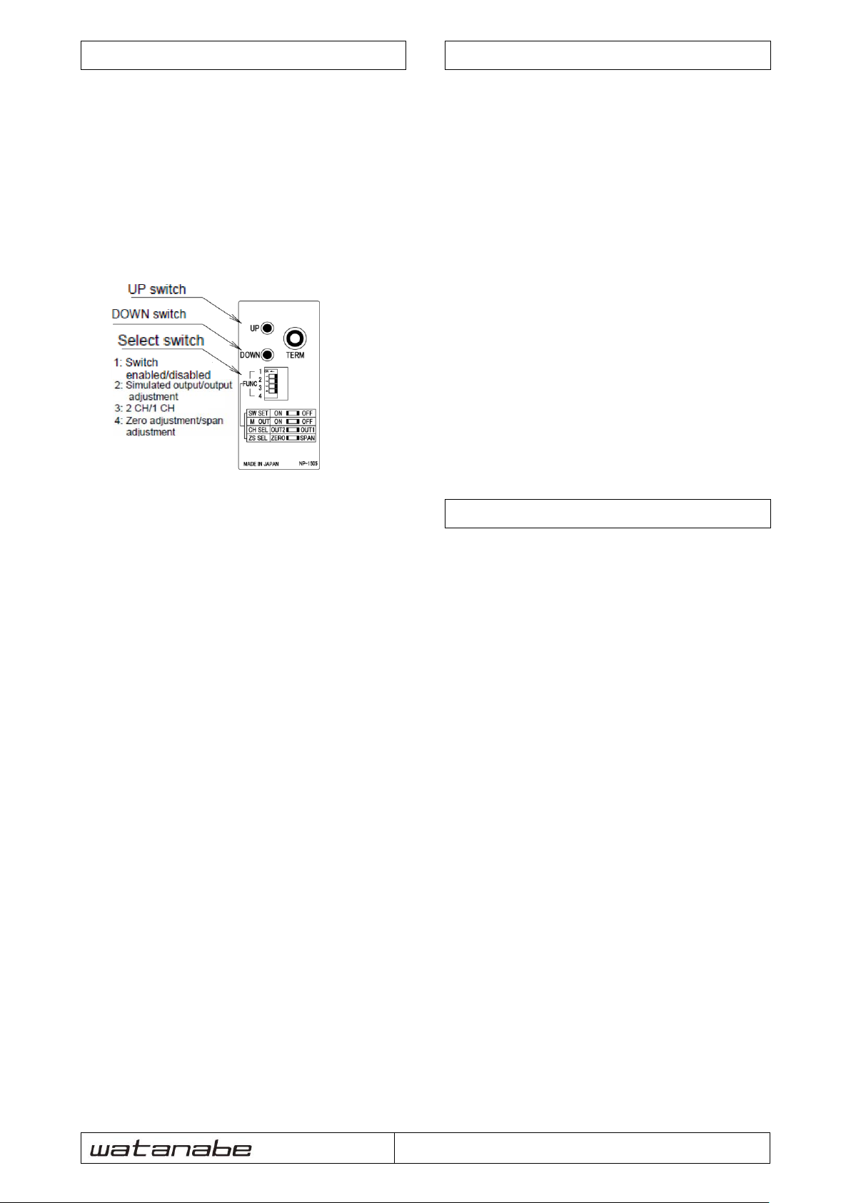
Output adjustment is performed with the setting switch on
the front side of this product.
○ How to adjust
① Set the selection switch 1 (SW SET) to ON.
This action enables switch operation.
If the setting tool is connected, communication is shut
off.
② Set the selection switch 2 (M OUT) to OFF.
③ Set the selection switch 4 (ZS SEL) to ZERO.
Use the UP or DOWN switch to adjust the output to 0%
when a 0%-equivalent input is provided and the select
switch 3 (CH SEL) is set to OUT1 or OUT2.
④ Set the selection switch 4 (ZS SEL) to SPAN.
Use the UP or DOWN switch to adjust the output to 100%
when a 100%-equivalent input is provided and the select
switch 3 (CH SEL) is set to OUT1 or OUT2.
⑤ Provide a 0%-equivalent input signal again to make sure
that the output is 0%.
If the output deviates, repeat the steps and .
⑥ Set the selection switch 1 to OFF after completion of
adjustment.
At this moment, the adjusted values are written into the
internal memory and switch operation becomes disabled.
* The adjusted values are written into the internal memory
and turning on or off the power does not clear the values.
To restore the settings to factory defaults, use the setting
tool to initialize the settings.
The write limit to the internal memory is 10,000 times at
minimum.
* If the power is turned off during adjustment, the adjusted
values are not written into the internal memory.
* approximately ±10% fs.
10. Simulated Output Function
This product is equipped with the simulated output function
to conduct tests including connection test.
The simulated output is performed with the setting switch
on the front side of this product. (Refer to the drawing in
Section 9 for the switch position.)
○Simulated output procedure
① Set the selection switch 1 (SW SET) to ON
This action enables switch operation.
If the setting tool is connected, communication is shut
off.
② Set the selection switch 2 (M OUT) to ON.
③ The simulated output is provided to the channel selected
with the selection switch 3 (CH SEL). (An output
according to an input is provided to the unselected
channel.)
The simulated output value varies with unipolar or bipolar
setting.
Use of the UP and DOWN switches provides users with 3
steps of outputs.
Unipolar: (DOWN) 0% ⇔ 50% ⇔ 100% (UP)
Bipolar: (DOWN) -100% ⇔ 0% ⇔ 100% (UP)
④ Set the selection switch 1 to OFF after completion of
adjustment.
11. Operation beyond Specifications
1) Excessive input
If an input signal beyond the upper limit is provided, the
output signal increases almost in proportion to the input
until approximately 120% fs of scaling setting. But even if
an excessive input signal is provided more, the output
signal does not increase any more.
2) Insufficient input
The output is described below when an input signal below
the lower limit is provided.
(a) For unipolar setting, the output signal decreases almost
in proportion to the input until approximately -20% fs
of scaling setting. But even if an insufficient input
signal is provided more, the output signal does not
decrease any more.
(b) For bipolar setting, the output signal decreases almost in
proportion to the input until approximately -120% fs of
scaling setting. But even if an insufficient input signal
is provided more, the output signal does not decrease
any more.
3) Load beyond specifications
(a) For current output, if the input exceeds the “range of
allowable load resistance”, the output is provided
almost in proportion to the input until the voltage
between the output terminals becomes approximately
15 volts. But if the output becomes larger, the output is
saturated resulting in larger error.
(b) For voltage output, if the input falls below the “range of
allowable load resistance”, the output is saturated
resulting in larger error.
Page 4
6-16-19, JINGUMAE, SHIBUYA-KU, TOKYO 150-0001, JAPAN
TEL: +81-3-3400-6147 FAX: +81-3-3409-3156
4/4 IM0873-00
12. PC Settings
The dedicated setting tool of this product allows users to
specify the input/output parameters listed below.
Refer to the instruction manual for the setting tool for
further information.
(Refer to the instruction manual for the setting tool also for
the settable arithmetic function.)
Password
4 one-byte characters
Comment
16 one-byte characters
(8 two-byte characters)
Computing range
Selection between unipolar (0 to 100%)
and bipolar (-100 to 100%) for
input/output signal processing
(Default: unipolar)
Input scaling
(Input % range
adjustment)
Any value within input range (±120%
fs)
Input filter
Use or nonuse of moving average
processing
(Default: use)
Input low level cut
Low level cut value of input signal in %
(None or 0.00 to 120.00%)
(Default: none)
*Disabled at bipolar setting
Ratio and bias
(Functions ①,②
default
arithmetic setting)
Output in alignment relative to input
Specifying ratio (-9.999 to 9.999) and
bias (-999.99 to 999.99)
(Default: ratio of 0.500 and bias of 0.00)
Addition and
subtraction
(Function ⑤ default
arithmetic setting)
Output resulting from adding to or
subtracting from input Specifying
coefficient (-1000.0 to 1000.0) for each
input
(Default: 100.0)
Output scaling
(Output % range
adjustment)
Any value within output range
Voltage: ±120% fs of output range
Current: -20 to +120% fs of output
range
Output low level cut
Low level cut value of output in %
(None or 0.00 to 120.00%)
(Default: none)
* Disabled at bipolar setting
Startup delay time
Period from power-on to output start (0
to 99 sec.)
(Default: 0)
Simulated input/output
Simulated input/output in % or real
quantity
Data monitor
Input/output monitoring in % and real
quantity (This operation also can be
performed at settings.)
Initialization
Restored to factory defaults
* The settings can be stored in the flash memory located in
the converter main unit. The write limit to the memory is
10,000 times at minimum.
(Retention period: 100 years at minimum)
* Do not write to the memory during operation.
(The product may unstably operate during writing.)
* The numbers within the parentheses such as function ①
and function ② indicate the setting position in
“Conversion/Arithmetic Setting” for the setting tool. Refer
to the instruction manual for the setting tool for arithmetic
items and operator.
13. Guarantee
This product is guaranteed for 5 years after delivery. If a
failure occurs under normal operation during the guaranteed
period, contact your dealer or us as soon as possible.
We will collect the product and repair it free of charge, or
replace the product with new one.
We shall not be liable for use of this product that was
disassembled or modified or under abnormal conditions.
 Loading...