

WATANABE WPMZ-5, WPMZ-6, MAX Induction SM-261R, MAX Induction SM-263R, MAX Induction SM-263RU Instruction Manual
...
WPMZ series
Modbus communication
instruction manual
Supported module type
WPMZ-5/6
Ver.1.30
Instruction manual number IM-0862-02

WPMZ Series Modbus communication instruction manual
IM-0862-02
Number of pages:109
1
Table of contents
INTRODUCTION ....................................................................................................................................... 2
1. OVERVIEW ............................................................................................................................................ 3
2. MODULE COMMUNICATION SPECIFICATION ................................................................................ 4
2-1. SUPPORTED MODULES ............................................................................................................................ 4
2-2. MODULE COMMUNICATION SPECIFICATION ............................................................................................. 4
2-3. MODULE WIRING (RS-485 COMMUNICATION OPTION) ............................................................................. 5
2-3-1. Wiring method ................................................................................................................................ 5
2-3-2. Connection terminal ....................................................................................................................... 5
2-3-3. Configuration diagram example .................................................................................................... 6
2-4. MODULE WIRING (RS-232C COMMUNICATION OPTION) .......................................................................... 8
2-4-1. Connection terminal ....................................................................................................................... 8
2-4-2. Configuration diagram example .................................................................................................... 8
3. MODBUS COMMUNICATION SPECIFICATION .................................................................................................... 9
3-1. COMMUNICATION PROCEDURE ................................................................................................................ 9
3-2. TRANSMISSION SWITCHING TIME ............................................................................................................ 9
3-3. MESSAGE ............................................................................................................................................... 10
3-3-1. Composition of messages ............................................................................................................. 10
3-3-2. Message Contents ......................................................................................................................... 10
3-3-3. Types of data ................................................................................................................................. 10
3-3-4. Slave ID ......................................................................................................................................... 10
3-3-5. Function code ................................................................................................................................. 11
3-3-6. Format Details ............................................................................................................................... 11
3-4. ERROR DETECTION ................................................................................................................................ 17
3-4-1. CRC-16 .......................................................................................................................................... 17
3-4-2. Calculation of CRC-16 .................................................................................................................. 17
3-5. ERROR MESSAGE ................................................................................................................................... 20
4. COMMUNICATION EXAMPLE .......................................................................................................... 21
4-1. WPMZ-5/6 ............................................................................................................................................ 21
4-1-1. Acquire measurement data .......................................................................................................... 21
4-1-2. Change control parameters .......................................................................................................... 22
4-1-3. Change setting parameters .......................................................................................................... 23
5. ADDRESS MAP .................................................................................................................................... 26
5-1. WPMZ-5/6 ............................................................................................................................................ 26
5-1-1. Setting and control parameters ................................................................................................... 26
5-1-2. Measurement data...................................................................................................................... 105
6. TROUBLESHOOTING........................................................................................................................ 108
6-1. ABOUT COMMUNICATION ..................................................................................................................... 108
6-1-1. Communication abnormal .......................................................................................................... 108
6-1-2. The acquired data is abnormal .................................................................................................. 108
Modbus is a registered trademark of Modicon Inc. (AEG Schneider Automation International S.A.S.).

WPMZ Series Modbus communication instruction manual
IM-0862-02
Number of pages:109
2
Introduction
This instruction manual explains notes, information and setting method when using Modbus communication of
WPMZ series.
Please observe the following in order to use the product correctly and safely.
○ Please read this instruction manual thoroughly before use and use it properly.
○ Before constructing the system, carefully read the Modbus compatible products and other equipment 's
instruction manuals to be used, and use them correctly.
○ After reading, carefully keep it and read it when you need it.
Usage restrictions
● Please note that the contents of this manual may be changed without notice.
We will not be held responsible in any case for special damages, indirect
damages, losses caused by this manual.
In this operation manual, hexadecimal data is indicated by appending "H" after the numerical value. Nothing is
appended to decimal data.
Example) Hexadecimal number: 123H, decimal number: 123

WPMZ Series Modbus communication instruction manual
IM-0862-02
Number of pages:109
3
1. Overview
We will explain the specification of Modbus communication of WPMZ series.
This manual is intended for engineers who connect from Modbus Master to Modbus compatible products and
create processing to collect settings and data.
As a Modbus master, it is assumed to be a PC or Programmable Logic Controller (PLC). Please
prepare equipment to be used for Modbus master in advance.
First, refer to "2. Module communication specification" and set the module (WPMZ - 5/6) connected to
the Modbus master so that it conforms to the communication specifications.
Then refer to "5. Address Map" of the corresponding module according to "3. Modbus communication
specification" and set and read the necessary items.

WPMZ Series Modbus communication instruction manual
IM-0862-02
Number of pages:109
4
2. Module communication specification
2-1. Supported Modules
The corresponding modules assumed in this manual are as follows.
WPMZ-5
WPMZ-6
2-2. Module communication specification
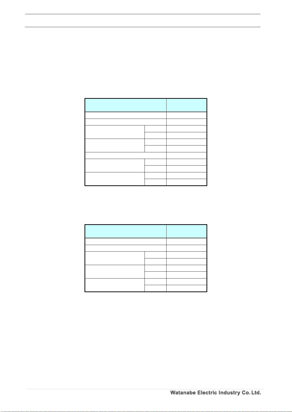
The communication specifications when connecting to each module are as shown in the table below.
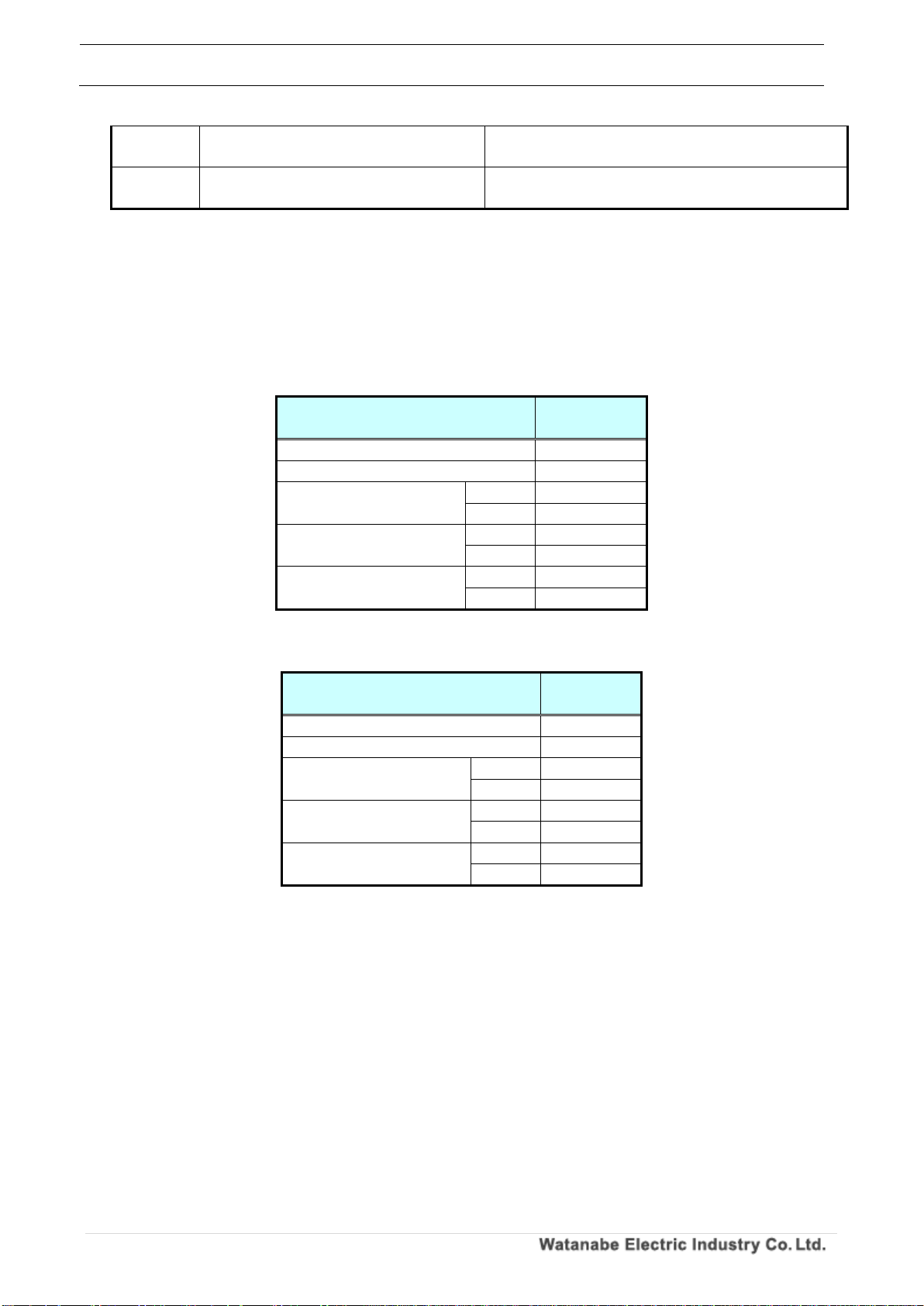
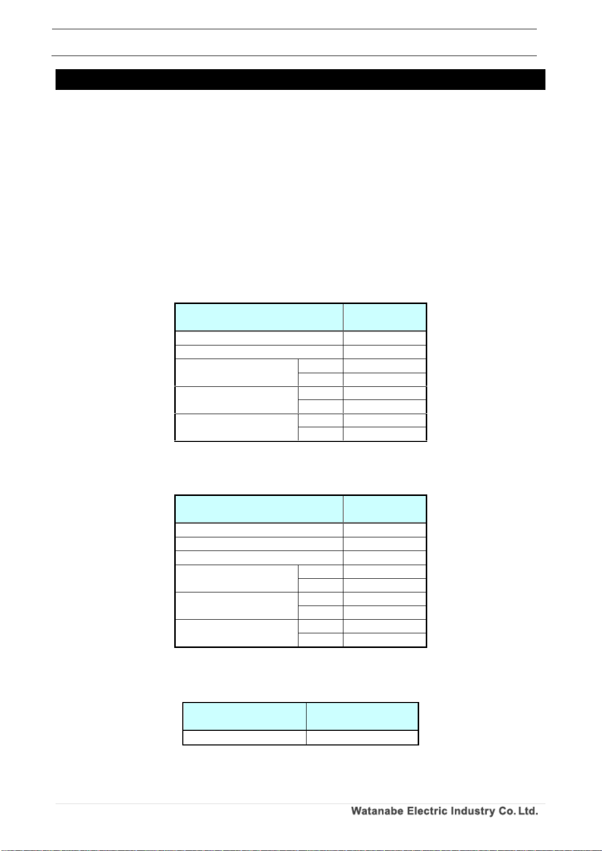
Table 2.1 Communication specification of module (RS-485 communication option)
WPMZ-5/6
Standard
RS-485 compliant
Protocol
Modbus(RTU)
Synchronous mode
Asynchronous type
Communication method
2-wire half-duplex
Error detection method
CRC-16
communication speed
9600bps、19200bps、38400bps
Data length
8 (fixed)
Start bit
1(fixed)
Parity bit
Selection from eve, odd, none
Stop bit
1、2
(Stop bit 2 can be set only when there is no parity)
Signal name used
Non-inverted (+), inverted (-)
Terminating resistance
Approximately 120 Ω (Connected by short-circuiting TERM
terminals)
Number of connected units
31 (number of slave devices)
Configurable address
1~31 (0 can not be used)
Transmission distance (total)
1.2km
※For CE mark conformance, less than 30 m
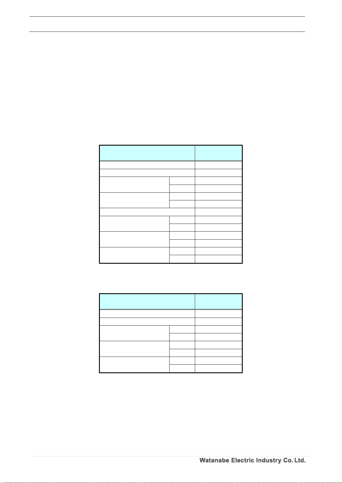
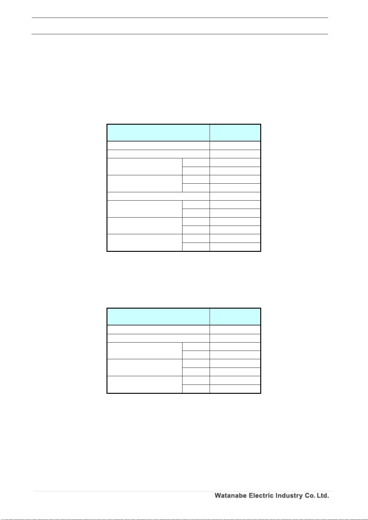
Table 2.2 Module communication specification (RS-232C communication option)
WPMZ-5/6
Standard
RS-232C compliant
Protocol
Modbus(RTU)
Synchronous mode
Asynchronous type
Communication method
Full duplex
Error detection method
CRC-16
communication speed
9600bps、19200bps、38400bps
Data length
8 (fixed)
Start bit
1(fixed)
Parity bit
Selection from eve, odd, none
Stop bit
1、2
(Stop bit 2 can be set only when there is no parity)
Signal name used
TXD、RXD、SG
Terminating resistance
-
Number of connected units
1 (number of slave devices)
Configurable address
1 only (0 can not be used)
Transmission distance (total)
15m
WPMZ Series Modbus communication instruction manual
IM-0862-02
Number of pages:109
5
2-3. Module wiring (RS-485 communication option)
2-3-1. Wiring method
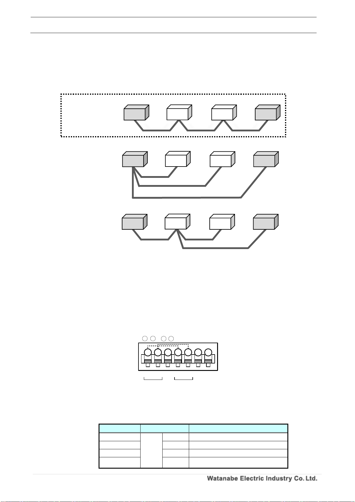
The Modbus communication wiring is wired in a daisy chain (daisy chaining).
If there are multiple branches from the star wiring or module, it may not be able to communicate
properly.
2-3-2. Connection terminal
This section describes the Modbus (RS485) connection terminals of the module.
1. WPMZ-5/6
Modbus (RS485) connection terminal of WPMZ-5/6 is as shown below.
28 and 31, 29 and 32 are conducting inside the equipment respectively.
(Since the connector inside does not have continuity, communication lines and remove the connector
will be disconnected.)
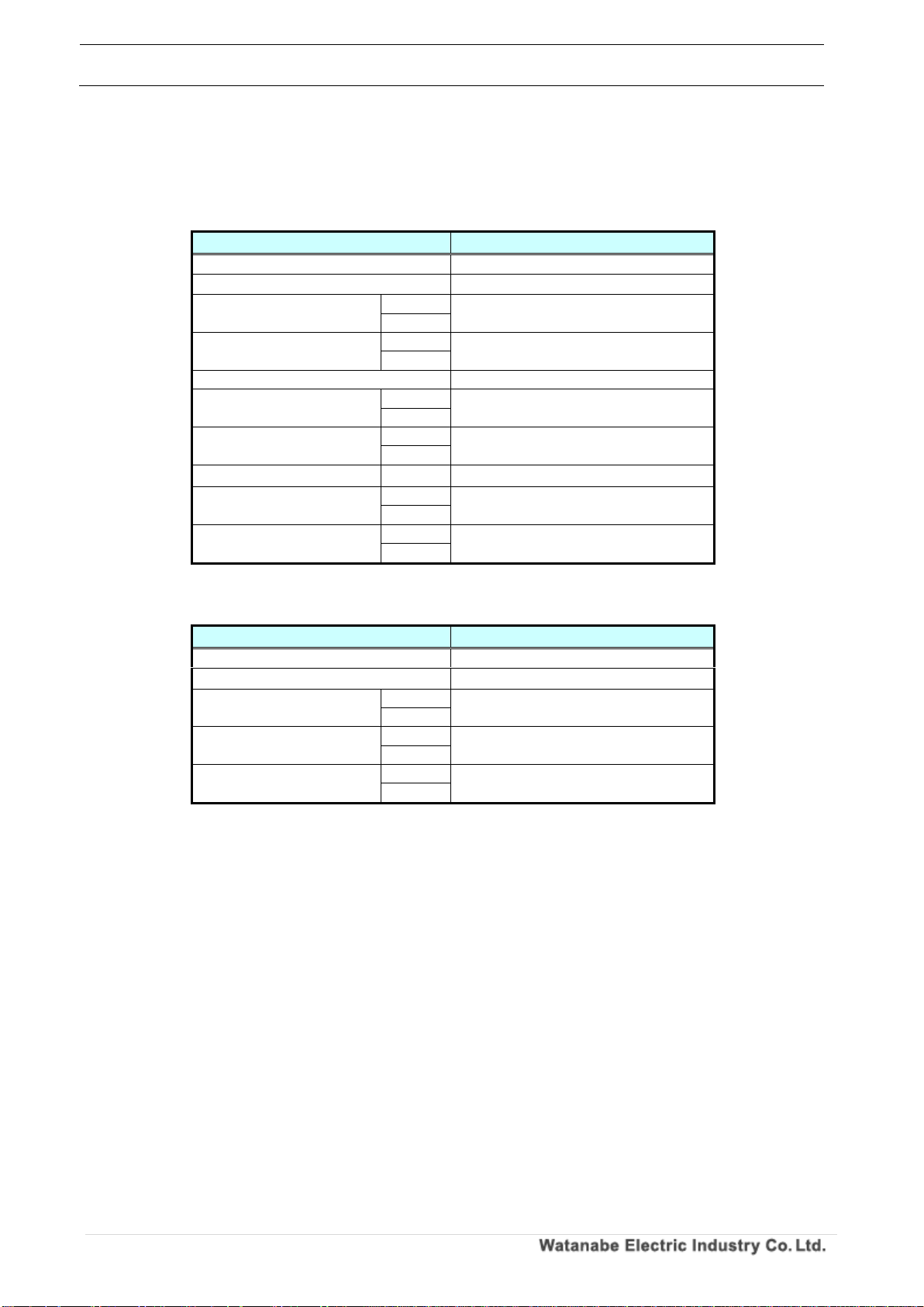
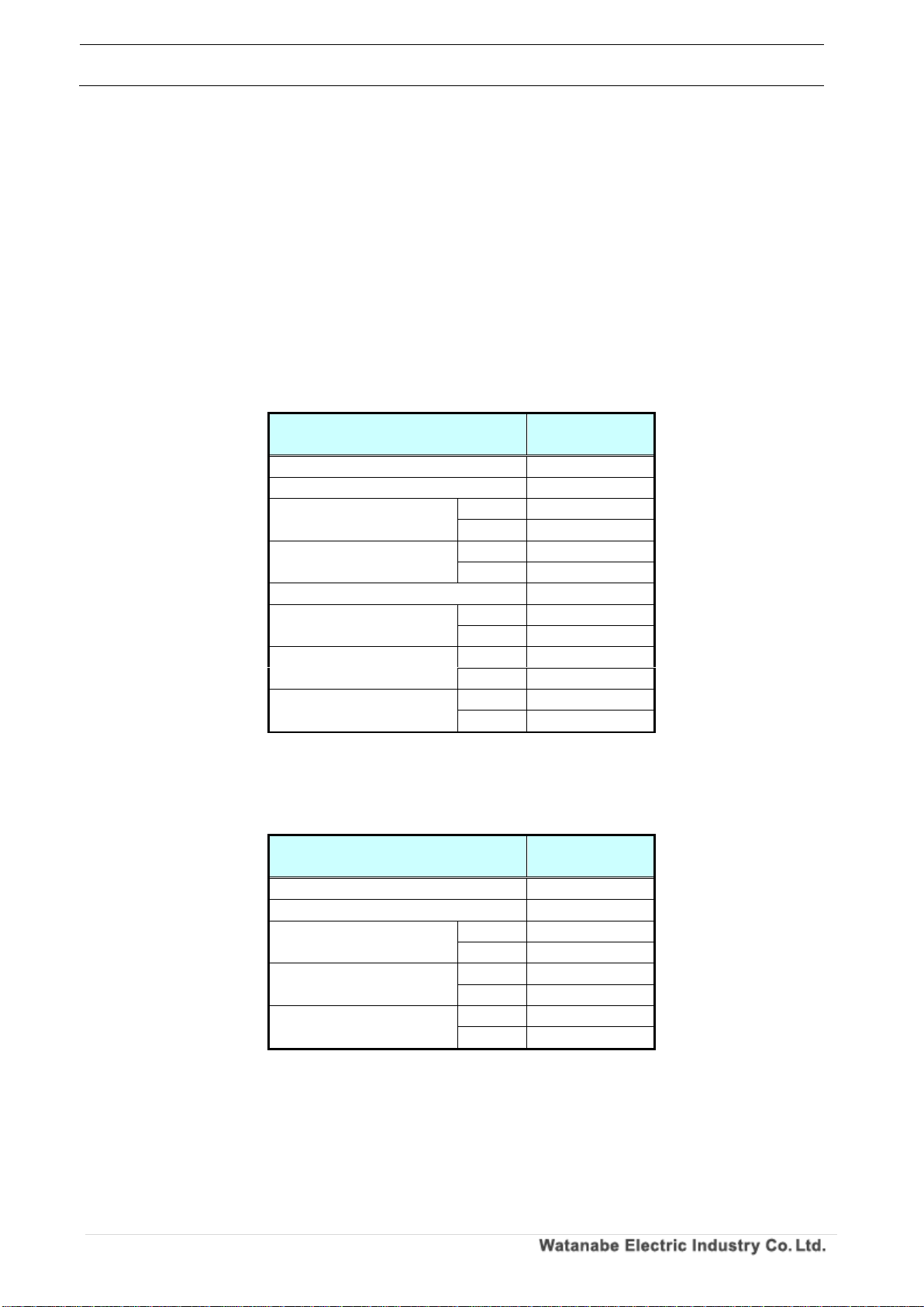
Table 2.3 Connector contents
Symbol
Contents
28,31
RS485
+
Non-inverting signal
29,32
-
Inverting signal
30
SG
Signal ground
33,34
Terminal resistance (120Ω)terminals
* Short 33 and 34 to be enable the resistance.
Figure 2.1 Wiring of Modbus communication
terminal
terminal
terminal
terminal
terminal
terminal
Correct wiring
(Daisy chain)
Incorrect wiring
(Star wiring)
Incorrect wiring
(There is a branch
on the way)
Figure 2.2 Modbus communication wiring
+
RS-485
TERM
TERM
SG
-
+
RS-485
-
34
28 29
30
31
32
33
* 、 & 、 :connected internally
28 31
29 32
Suitable wire:AWG24 to 16
Master
Master
Master
WPMZ Series Modbus communication instruction manual
IM-0862-02
Number of pages:109
6
2-3-3. Configuration diagram example
The configuration example of WPMZ - 5/6 is shown below.
1. About communication cable
Please use a shielded cable that meets the following specifications.
Table 2.4 Communication cable specification
Product name
Size
Total cable extension
WPMZ-5/6
AWG24~16
1.2km or less
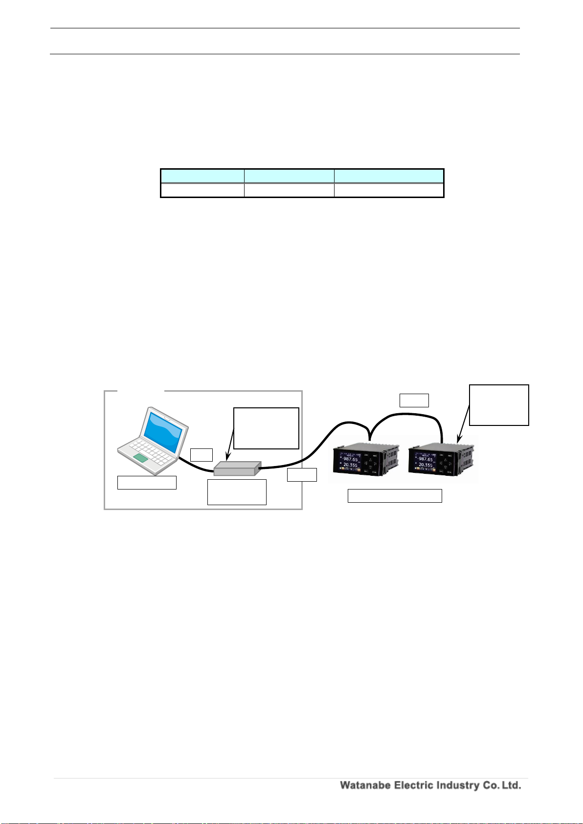
2. About connection of terminating resistor
Up to 31 slaves (modules) can be connected.
At that time, please set the terminating resistor for the module which becomes the terminal equipment
of the line.
In the case of WPMZ-5/6, connect the TERM terminals together.
If this product is not a terminal equipment of the line, please do not set the termination resistor.
When connecting via Modbus using the USB - RS 485 converter, even if the master is a personal
computer, set the terminating resistor in the USB - RS 485 converter. (See the figure below)
Note: Do not configure multiple masters to connect to the same slave (module).
Communication may not be performed correctly and data may not be taken.
Figure 2.3 Terminating resistance when USB-RS 485 converter is used
Master
Set the
terminating
resistance
Set the
terminating
resistance
USB-RS485
converter
Computer
Slave (module)
USB
RS485
RS485
WPMZ Series Modbus communication instruction manual
IM-0862-02
Number of pages:109
7
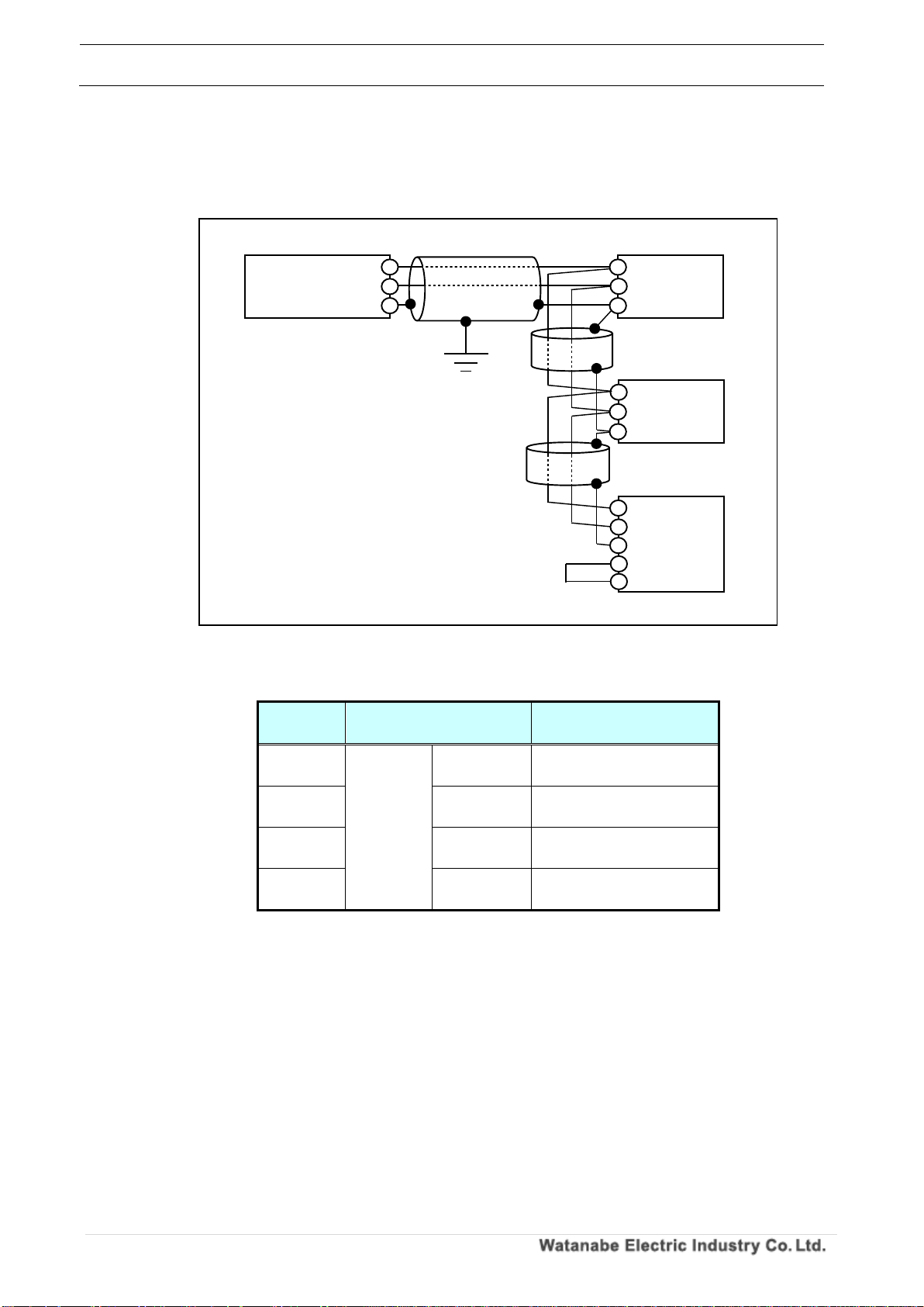
3. Connection diagram
The Modbus connection of WPMZ - 5/6 is shown below.
Please set the terminating resistance to the master and slave at the final end (WPMZ in the figure
below).
Table 2.5 Modbus connection terminal (WPMZ - 5/6)
Terminal
number
symbol
Contents
28,31
RS485
+
Communication plus
terminal
29,32
-
Communication minus
terminal
30
SG
Communication SG
terminal
33,34
TERM (※)
Terminal resistor terminal
(120 Ω)
※ When connecting the TERM terminals to each other, the terminating resistance becomes
effective.
Figure 2.4 Modbus connection of WPMZ-5/6
With
terminating
resistance
Shield cable
Shield cable
※ When WPMZ - 5/6 is
terminated, connect the
TERM terminals together.
Twisted pair wire
WPMZ-5/6:AWG24~16
Slave
Slave
WPMZ
Master
SG
SG
+
+
+
+
SG
S
T
T
Shield cable
WPMZ Series Modbus communication instruction manual
IM-0862-02
Number of pages:109
8
2-4. Module wiring (RS-232C communication option)
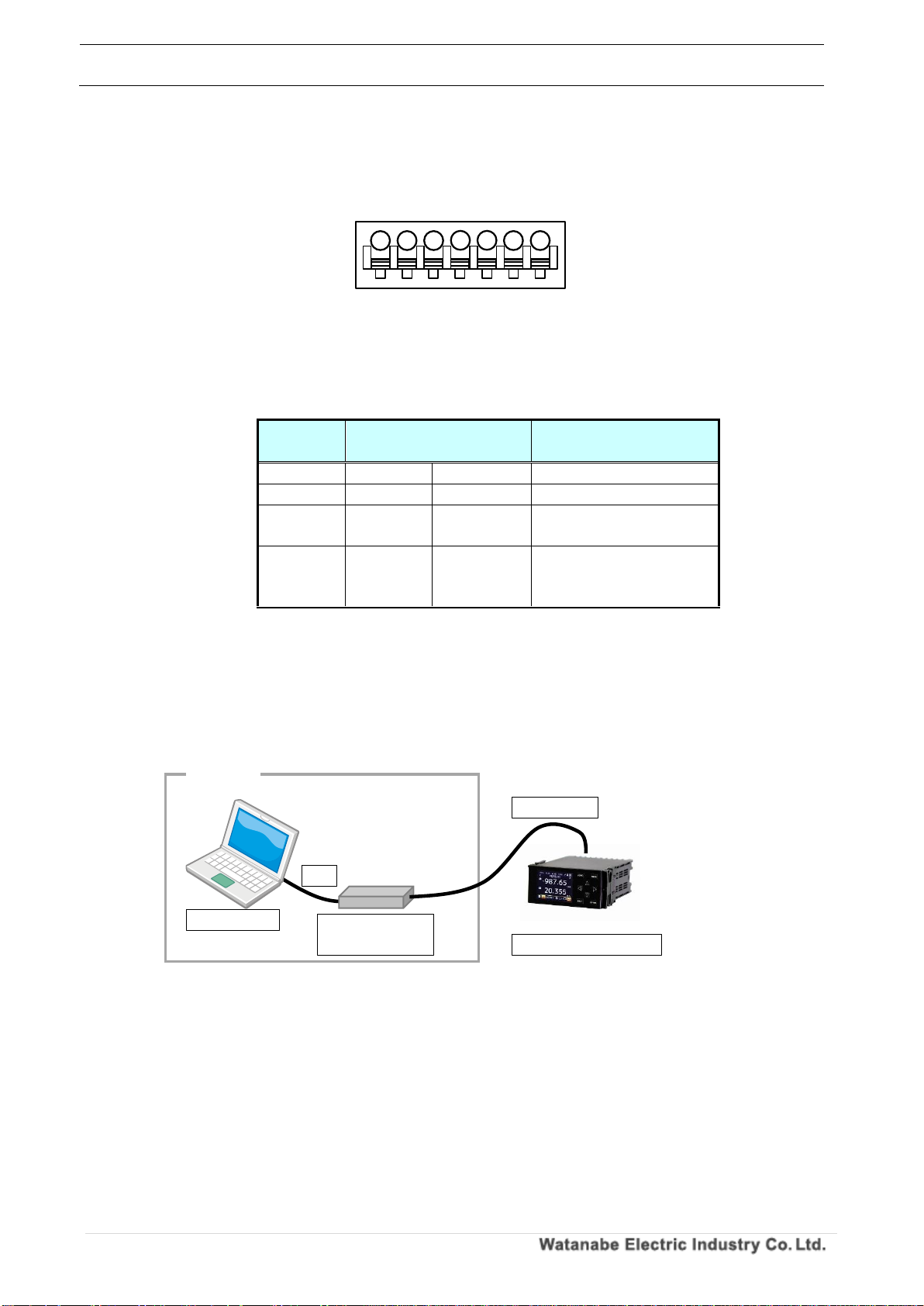
2-4-1. Connection terminal
The figure below shows the RS - 232C connection terminal of WPMZ - 5/6.
Table 2.6 Connector contents
Terminal
number
symbol
Contents
28 RXD
Receive terminal
29 TXD
Transmission terminal
30 SG
Common terminal of
communication function
31~34
NC
Not connected ※ Please
do not use as relay
terminal.
2-4-2. Configuration diagram example
The configuration example of WPMZ - 5/6 is shown below.
Master and slave (module) are connected 1: 1.
Specify "1" for the slave address of the Modbus protocol.
Figure 2.5 Wiring of RS-232C communication
Figure 2.6 When USB-RS232C converter is used
マスター
USB RS-232C
converter
computer
Slave (module)
USB
RS-232C
RXD
TXD
SG
NC
NC
NC
NC
34
28 29 30
31
32
33
Suitable wire:AWG24 to 16
WPMZ Series Modbus communication instruction manual
IM-0862-02
Number of pages:109
9
3. Modbus communication specification
Modbus is a single master / multislave system.
A message is sent from one Modbus master to the slave (module). The message is sent to the specified slave
(module).
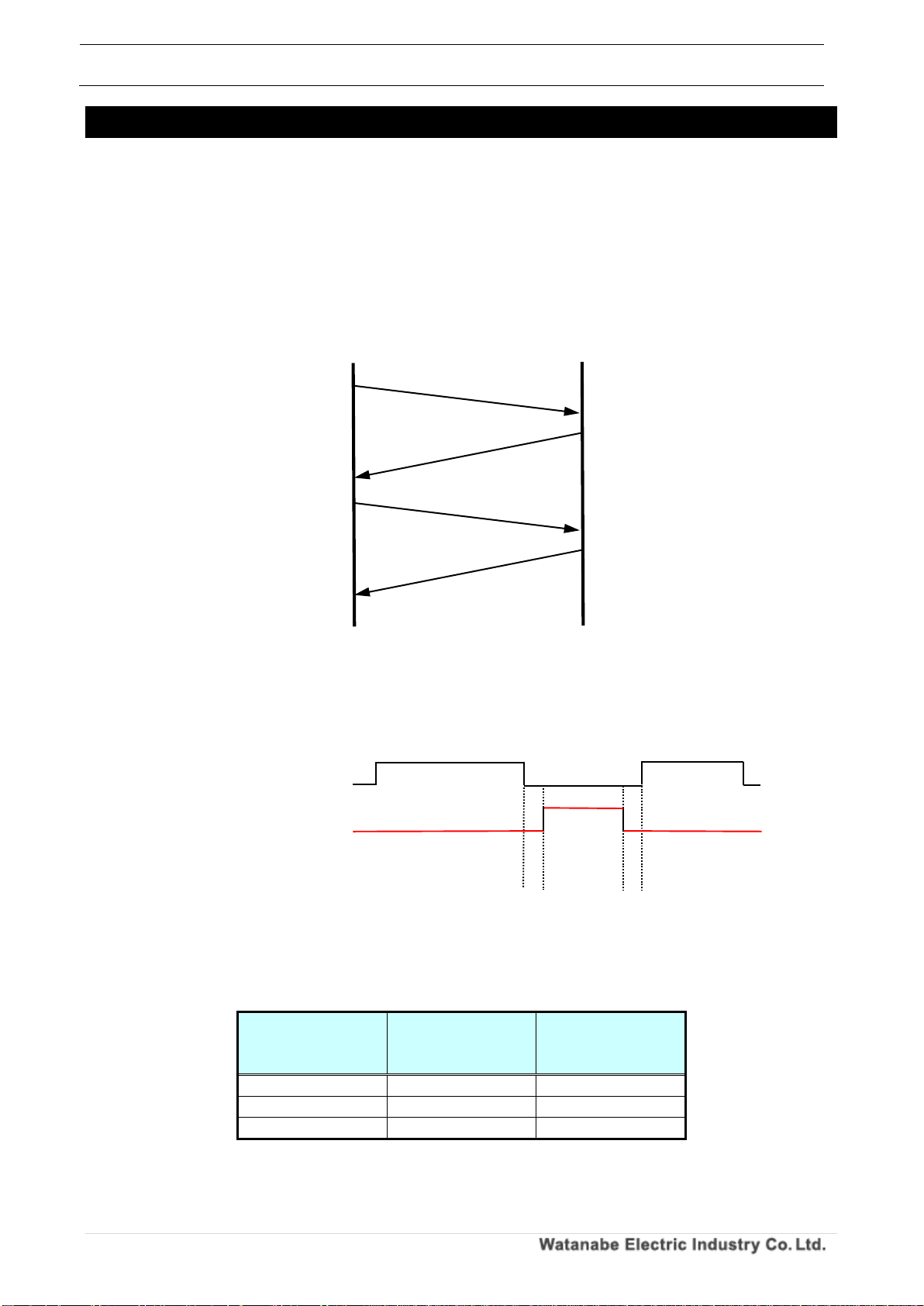
3-1. Communication procedure
When the master sends a command message, the slave (module) sends a response message to the
contents of the message.
The operations of the master side message and the slave side message are as follows.
3-2. Transmission Switching Time
In communication between master and slave, idle time for 3.5 characters is required for transmission /
reception switching.
Please refer to the table below for the idle time for 3.5 characters.
In the WPMZ-5/6 series, the communication speed and parity setting can be changed.
Table 3.1 3.5 character idle time (reference value)
communication
speed
With parity
(Even number, odd
number)
No parity
9600bps
4.01ms
3.65ms
19200bps
2.01ms
1.82ms
38400bps
1.00ms
0.91ms
Master
Slave
(module)
Command
message
Response
message
Command
message
Response
message
Figure 3.1 Communication procedure
Master side message
transmission
Slave side message
response
Idle time
Idle time
WPMZ Series Modbus communication instruction manual
IM-0862-02
Number of pages:109
10
3-3. Message
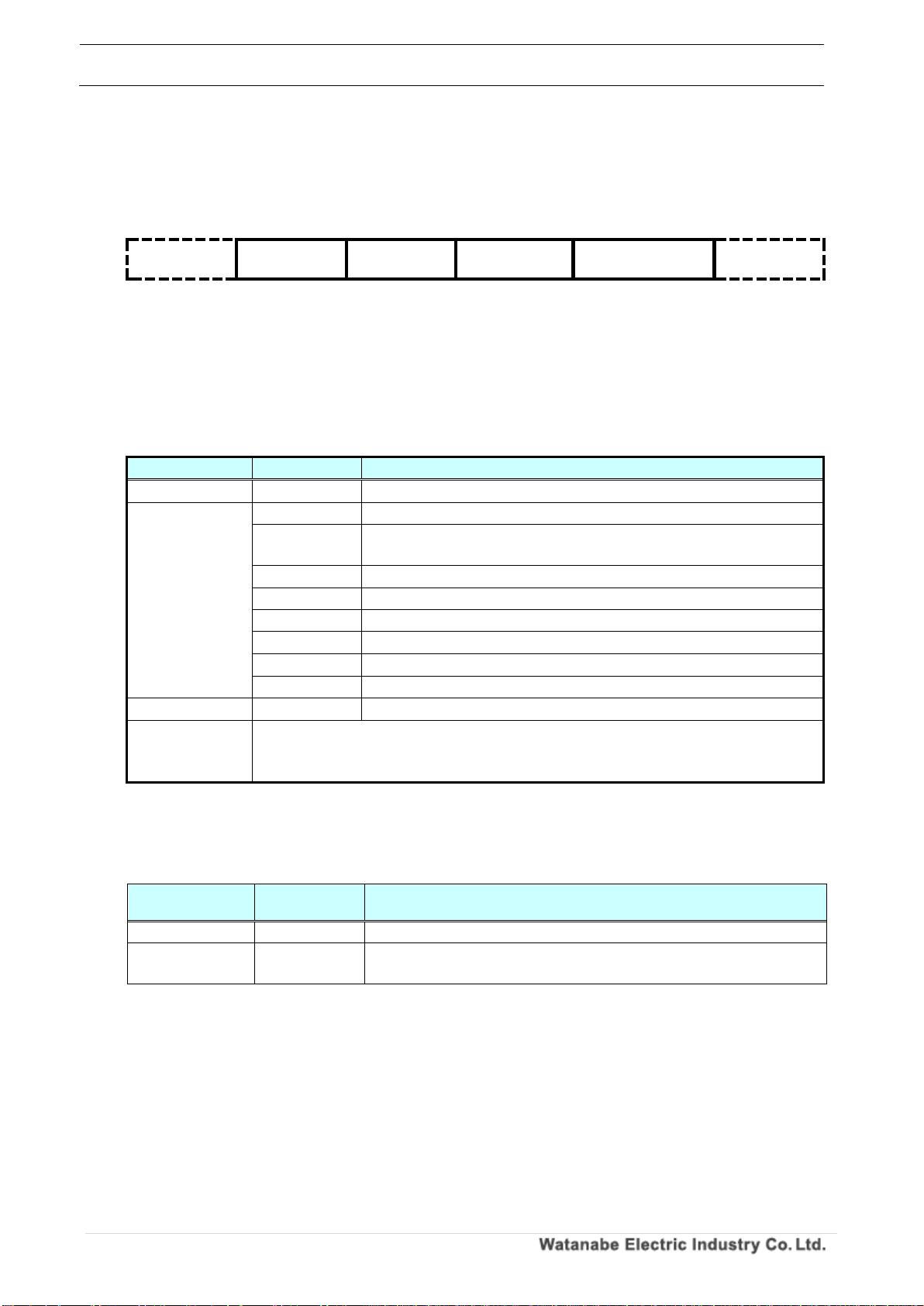
3-3-1. Composition of messages
After securing an idle interval of 3.5 character transmission time or longer, it transmits a communication
message and ends after an idle time of 3.5 character transmission time or more.
Id l e 3. 5
ch a r a ct e r s
Sl a ve I D
Fu n c t i o n
co d e
Th e d a t a
Er r or c h e c k
CRC-16
Id l e 3. 5
ch a r a ct e r s
1b y te
1b y te
2~ 250b y t e
(v a r i ab l e
le n g t h )
2b y te
3-3-2. Message Contents
In the structure of the above message, descriptions of data and contents that can be set are shown in
the table below.
Table 3.2 Message contents
item
Setting data
Contents
Slave ID
01~1FH
Slave ID (maximum number of connected units is 31)
Function code
03H
Read held register
04H
Read input register
(Read only address)
06H
Hold register 1 word write
08H
Diagnosis
0BH
Read event counter
0CH
Read event log
10H
Holding register Continuous write
11H
Read slave information
The data
-
Data (variable length by command)
Error check
(CRC-16)
Calculate CRC-16 from the slave ID to the last byte of the data and add CRC-16 (2
bytes) of the operation result to the data in the order of the lower byte and the
upper byte.
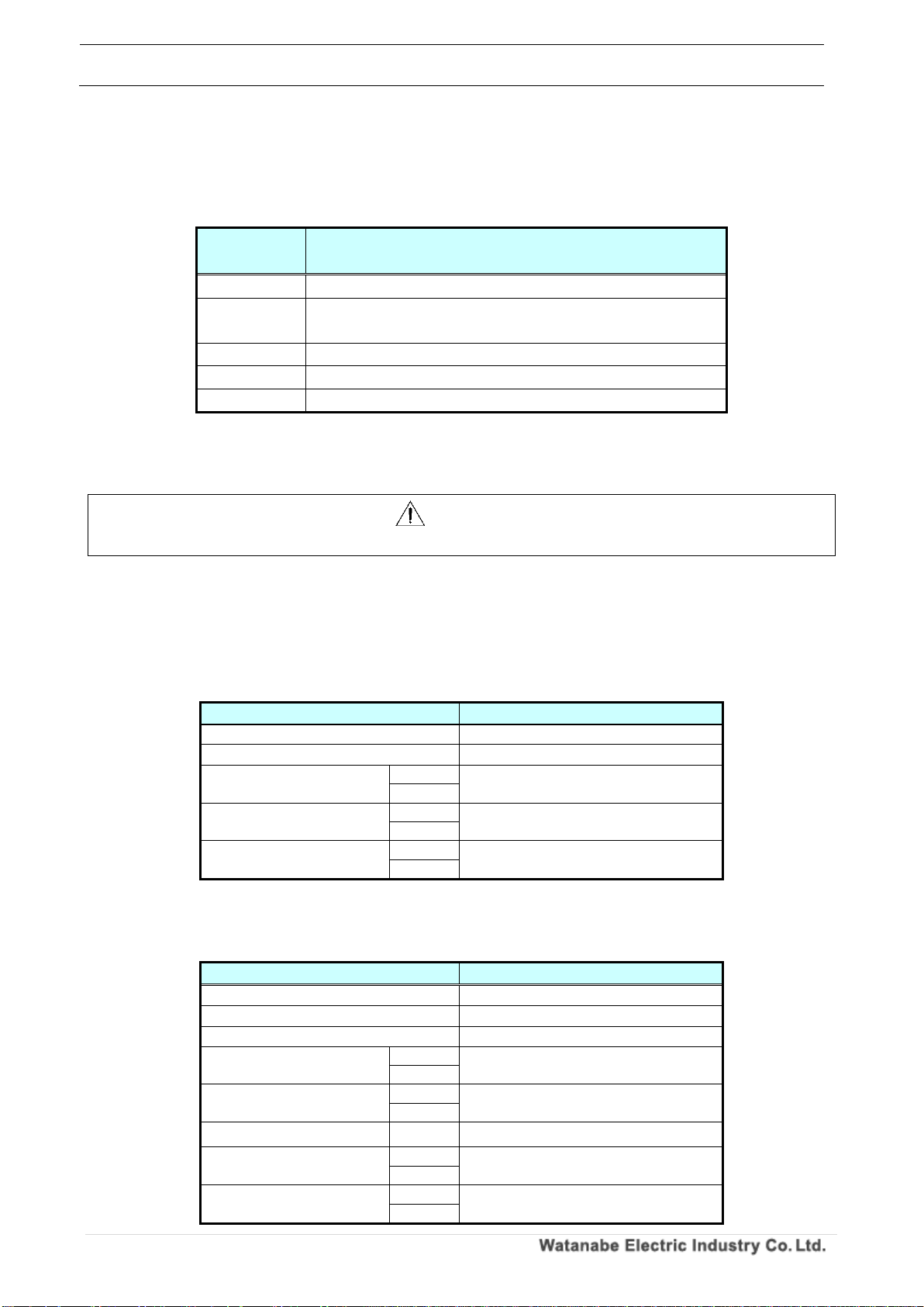
3-3-3. Types of data
Modbus data has two input register and holding register.
Table 3.3 Types of data
Types of data
Reading and
writing
Details
Input register
Read only
It is used to acquire the information in the slave.
Holding register
Reading and
writing
It is used to acquire and set slave control information / setting
information.
3-3-4. Slave ID
It returns a response message only when the received message matches the ID value set in the
module.
If they do not match, no response message is returned.
WPMZ Series Modbus communication instruction manual
IM-0862-02
Number of pages:109
11
3-3-5. Function code
The function code is a code that specifies the operation to be made slave, and it is included in the
message sent from the master to the slave.
The function codes described in this manual are shown in the table below.
Table 3.4 Function code list
Function
code
Feature Description
03H
Read held register
04H
Read input register
(Read only address)
06H
Hold register 1 word write
08H
Diagnosis
10H
Holding register Continuous write
3-3-6. Format Details
Explain the detailed format for each function code.
Caution
Please be aware that the error checking CRC in each format is added in order of lower byte and higher byte.
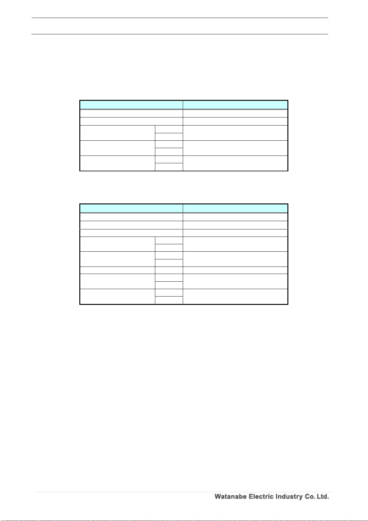
1. Function code 03H (Read held register)
Read the parameter value of the specified address.
Tran s miss i on a nd rece p tion for m at
◎Transmission data (master → slave (module))
Table 3.5 Function code 03H Transmission format
na m e
Tr a n s mi tt e d da ta
Sl a ve I D
01 ~ F F H
Fu n c t io n c o d e
03H
Ad d re s s
Up p e r
0000 ~ 27 0F H
Lo w er
Nu m be r o f w o r d s t o be
re a d( D a t a le n g th ÷ 2 )
Up p e r
0001 ~ 00 7D H
Lo w er
Er r or c h e c k
(CRC- 16)
Up p e r
0000 ~ FF F F H
Lo w er
※Specify the number of read words in units of data length for each address.
◎Received data (slave (module) → master)
Table 3.6 Function code 03H Reception format
na m e
Re c e i ve d d a t a
Sl a ve I D
01 ~ F F H
Fu n c t io n c o d e
03H
Nu m be r o f by te s r ea d
2 × n u mb e r of r e a d w or d s
Fi r s t w o r d d a t a
Up p e r
0000 ~ FF F F H
Lo w er
Ne x t w o r d da ta
Up p e r
0000 ~ FF F F H
Lo w er
~
~
~
Th e l as t w or d d a t a
Up p e r
0000 ~ FF F F H
Lo w er
Er r or c h e c k
(CRC- 16)
Lo w er
0000 ~ FF F F H
Up p e r
WPMZ Series Modbus communication instruction manual
IM-0862-02
Number of pages:109
12
2. Function code 04H (Read input register [Read only address])
Read the measurement value of the specified read-only address.
Tran s miss i on a nd r ece p tion form a t
◎Transmission data (master → slave (module))
Table 3.7 Function code 04H Transmission format
na m e
Tr a n s mi tt e d da ta
Sl a ve I D
01 ~ F F H
Fu n c t io n c o d e
04H
Ad d re s s
Up p e r
0000 ~ 27 0F H
Lo w er
Nu m be r o f w o r d s t o be
re a d( D a t a le n g th ÷ 2 )
Up p e r
0001 ~ 00 7D H
Lo w er
Er r or c h e c k
(CRC- 16)
Lo w er
0000 ~ FF F F H
Up p e r
※Specify the number of read words in units of data length for each address.
◎Received data (slave (module) → master)
Table 3.8 Function code 04H Reception format
na m e
Re c e i ve d d a t a
Sl a ve I D
01 ~ F F H
Fu n c t io n c o d e
04H
Nu m be r o f by te s r ea d
2 × n u mb e r of r e a d w or d s
Fi r s t w o r d d a t a
Up p e r
0000 ~ FF F F H
Lo w er
Ne x t w o r d da ta
Up p e r
0000 ~ FF F F H
Lo w er
~
~
~
Th e l as t w or d d a t a
Up p e r
0000 ~ FF F F H
Lo w er
Er r or c h e c k
(CRC- 16)
Lo w er
0000 ~ FF F F H
Up p e r

WPMZ Series Modbus communication instruction manual
IM-0862-02
Number of pages:109
13
3. Function code 06H (Write 1 word of holding register)
Writes 1 word (2 bytes) of data to the specified writable address.
Tran s miss i on a nd r ece p tion form a t
◎Transmission data (master → slave (module))
Table 3.9 Function code 06H Transmission format
na m e
Tr a n s mi tt e d da ta
Sl a ve I D
01 ~ F F H
Fu n c t io n c o d e
06H
Ad d re s s
Up p e r
0000 ~ 27 0F H
Lo w er
Wr i te w o r d d a t a
Up p e r
0000 ~ FF F F H
Lo w er
Er r or c h e c k
(CRC- 16)
Lo w er
0000 ~ FF F F H
Up p e r
◎Received data (slave (module) → master)
Table 3.10 Function code 06H Reception format
na m e
Re c e i ve d d a t a
Sl a ve I D
01 ~ F F H
Fu n c t io n c o d e
06H
Ad d re s s
Up p e r
0000 ~ 27 0F H
Lo w er
Wr i te w o r d d a t a
Up p e r
0000 ~ FF F F H
Lo w er
Er r or c h e c k
(CRC- 16)
Lo w er
0000 ~ FF F F H
Up p e r

WPMZ Series Modbus communication instruction manual
IM-0862-02
Number of pages:109
14
Fun c tion code 08H ( dia g n osi s )
It is a communication that diagnoses the communication between the master and the slave and
diagnoses the module.
Tran s miss i on a nd r e cep t i on f orma t
◎Transmission data (master → slave (module))
Table 3.11 Function code 08H Transmission format
na m e
Tr a n s mi tt e d da ta
Sl a ve I D
01 ~ F F H
Fu n c t io n c o d e
08 H
Di a g n os t i c s u b c o d e
Up p e r
0000 ~ 0012H
Lo w er
Da t a f i e l d
Up p e r
0000 ~ FF F F H
Lo w er
Er r or c h e c k
(CRC- 16)
Lo w er
0000 ~ FF F F H
Up p e r
◎Received data (slave (module) → master)
Table 3.12 Function code 08H Reception format
na m e
Re c e i ve d d a t a
Sl a ve I D
01 ~ F F H
Fu n c t io n c o d e
08H
Di a g n os t i c s u b c o d e
Up p e r
0000 ~ 0015H
Lo w er
Da t a f i e l d
Up p e r
0000 ~ FF F F H
Lo w er
Er r or c h e c k
(CRC- 16)
Lo w er
0000 ~ FF F F H
Up p e r
Dia g n osti c su b cod e an d dia g nost i c c o nten t
The corresponding diagnostic subcode is shown in the table below.
Table 3.13 Corresponding diagnostic subcode
Diagnostic
subcode
Diagnostic name
Diagnosis contents
00H
Return Query Data
It returns the data of the transmitted data field as it
is.
01H
Restart Communications Option
Restart communication.
02H
Return Diagnostics Register
Returns diagnostic register (fixed as 0 because it is
not used).
04H
Force Listen Only Mode
Set the slave to receive only mode.
0AH
Clear Counters and Diagnostic Register
Clear all counters and diagnostic registers.
0BH
Return Bus Message Count
Returns the total of messages detected by the slave.
0CH
Return Bus Communication Error Count
Returns the total of CRC errors detected by the
slave.
0DH
Return Bus Exception Error Count
Returns the sum of exception responses of Modbus
returned by the specified slave.
0EH
Return Server Message Count
Returns the total of messages received by the
specified slave.
0FH
Return Server No Response Count
Returns the total of messages for which the
specified slave did not respond.
10H
Return Server NAK Count
Returns the total of messages that the specified
slave returned NAK.
WPMZ Series Modbus communication instruction manual
IM-0862-02
Number of pages:109
15
11H
Return Server Busy Count
Returns the number of times slave, busy, exception
response returned by the specified slave.
12H
Return Bus Character Overrun Count
Returns the number of times a character overrun
error occurred on the specified slave.
Dia g n osti c fu n cti o n co m muni cati o n exam p le
Communication is performed with the diagnosis subcode 00H (Return Query Data) for the module
with slave ID 01H.
An example of specifying 55AAH for write word data is shown below.
・Transmission data (master → slave (module))
Table 3.14 Function code 08H Transmission data
na m e
Tr a n s mi tt e d
da t a
Sl a ve I D
01H
Fu n c t io n c o d e
08H
Di a g n os t i c s u b c o d e
Up p e r
00H
Lo w er
00H
Da t a f i e l d
Up p e r
55H
Lo w er
AA H
Er r or c h e c k
(CRC- 16)
Lo w er
5F H
Up p e r
24H
・Received data (slave (module) → master)
Table 3.15 Function code 08H Receive data
na m e
Re c e i ve d
da t a
Sl a ve I D
01H
Fu n c t io n c o d e
08H
Di a g n os t i c s u b c o d e
Up p e r
00H
Lo w er
00H
Da t a f i e l d
Up p e r
55H
Lo w er
AA H
Er r or c h e c k
(CRC- 16)
Lo w er
5F H
Up p e r
24H
WPMZ Series Modbus communication instruction manual
IM-0862-02
Number of pages:109
16
4. Function code 10H (hold register consecutive write)
Writes contiguous data to the specified writable address.
Tran s miss i on a nd r e cep t i on f orma t
◎Transmission data (master → slave (module))
Table 3.16 Function code 10H Transmission format
na m e
Tr a n s mi tt e d da ta
Sl a ve I D
01 ~ F F H
Fu n c t io n c o d e
10H
St a rt a d d r es s
Up p e r
0000 ~ 27 0F H
Lo w er
Th e n um b e r o f d a t a
Up p e r
0002 ~ 0 1 FE H
Lo w er
Nu m be r o f by te s
01 ~ F F H
Fi r s t w r i t e w o r d da ta
Up p e r
0000 ~ FF F F H
Lo w er
Ne x t w r i t e w or d d at a
Up p e r
0000 ~ FF F F H
Lo w er
~
~
~
La s t wr i t e w o r d d a t a
Up p e r
0000 ~ FF F F H
Lo w er
Er r or c h e c k
(CRC- 16)
Lo w er
0000 ~ FF F F H
Up p e r
◎Received data (slave (module) → master)
Table 3.17 Function code 10H Reception format
na m e
Re c e i ve d d a t a
Sl a ve I D
01 ~ F F H
Fu n c t io n c o d e
10H
St a rt a d d r es s
Up p e r
0000 ~ 27 0F H
Lo w er
デー タ 数
Up p e r
0002 ~ 0 1 FE H
Lo w er
Er r or c h e c k
(CRC- 16)
Lo w er
0000 ~ FF F F H
Up p e r

WPMZ Series Modbus communication instruction manual
IM-0862-02
Number of pages:109
17
3-4. Error detection
3-4-1. CRC-16
CRC - 16 is 2 - byte error check data. The calculation range is from the slave ID at the head of the
message to the end of the data part.
The slave (module) calculates the CRC of the received message, and if it does not match the received
CRC code, it becomes no response and the function is not executed.
3-4-2. Calculation of CRC-16
To calculate the CRC, divide the transmission data by the generator polynomial (X16 + X15 + X2 + X0)
and set the remainder in the order of the lower byte and upper byte in the error check.
The following is an example of generating with command data from the master device.
① Area initialization: Substitute FFFFH for 【CRC - 16】.
② Assign the calculated value of 【CRC - 16】 XOR 【first data (here, slave ID data)】 to 【CRC -
16】.
③ Assign [CRC - 16] to the right by one bit shifted to [CRC - 16].
④ If CF (carry flag) = 1, substitute the calculated value of [CRC - 16] XOR A 001 H into [CRC -
16] according to 3) above. (CF shifts to the right when shifting right one bit when the least
significant bit is 1).
⑤ Repeat ③ and ④ above 8 times. After the end of 8 times, go to ⑥.
⑥ If the last data has been completed, add [CRC - 16] as a calculation result to the message and
exit. If not finished, go to ⑦.
⑦ Assign the calculated value of 【CRC - 16】 XOR 【next data】 to 【CRC - 16】 and go to ③.
WPMZ Series Modbus communication instruction manual
IM-0862-02
Number of pages:109
18
Calc ulat i on e x ampl e : P e rfor m CRC cal c ulat i on o f 01 0 4000 0 0002 .
Table 3.18 Calculated data example: 010400000002 (6 bytes data)
16
15
14
13
12
11
10 9 8 7 6 5 4 3 2 1 CF
説明
1 1 1 1 1 1 1 1 1 1 1 1 1 1 1
1
-
FFFFH
(initialization)
01 (1st byte)
0 0 0 0 0 0 0 0 0 0 0 0 0 0 0
1 -
1 1 1 1 1 1 1 1 1 1 1 1 1 1 1
0 - XOR top two rows
right shift 1st
0 1 1 1 1 1 1 1 1 1 1 1 1 1 1
1 0
right shift 2nd
0 0 1 1 1 1 1 1 1 1 1 1 1 1 1
1 1 CF became 1
1 0 1 0 0 0 0 0 0 0 0 0 0 0 0
1 - A001H 1 0 0 1 1 1 1 1 1 1 1 1 1 1 1 0 - XOR top two rows
right shift 3rd
0 1 0 0 1 1 1 1 1 1 1 1 1 1 1
1 0
right shift 4th
0 0 1 0 0 1 1 1 1 1 1 1 1 1 1
1 1 CF became 1
1 0 1 0 0 0 0 0 0 0 0 0 0 0 0
1 - A001H
1 0 0 0 0 1 1 1 1 1 1 1 1 1 1
0 - XOR top two rows
right shift 5th
0 1 0 0 0 0 1 1 1 1 1 1 1 1 1
1 0
right shift 6th
0 0 1 0 0 0 0 1 1 1 1 1 1 1 1
1 1 CF became 1
1 0 1 0 0 0 0 0 0 0 0 0 0 0 0
1 - A001H 1 0 0 0 0 0 0 1 1 1 1 1 1 1 1 0 - XOR top two rows
right shift 7th
0 1 0 0 0 0 0 0 1 1 1 1 1 1 1
1 0
right shift 8th
0 0 1 0 0 0 0 0 0 1 1 1 1 1 1
1 1 CF became 1
1 0 1 0 0 0 0 0 0 0 0 0 0 0 0
1 - A001H
1 0 0 0 0 0 0 0 0 1 1 1 1 1 1
0 - XOR top two rows
04 (2nd byte)
0 0 0 0 0 0 0 0 0 0 0 0 0 1 0
0 - 1 0 0 0 0 0 0 0 0 1 1 1 1 0 1 0 - XOR top two rows
right shift 1st
0 1 0 0 0 0 0 0 0 0 1 1 1 1 0
1 0
right shift 2nd
0 0 1 0 0 0 0 0 0 0 0 1 1 1 1
0 1 CF became 1
1 0 1 0 0 0 0 0 0 0 0 0 0 0 0
1 - A001H
1 0 0 0 0 0 0 0 0 0 0 1 1 1 1
1 - XOR top two rows
right shift 3rd
0 1 0 0 0 0 0 0 0 0 0 0 1 1 1
1 1 CF became 1
1 0 1 0 0 0 0 0 0 0 0 0 0 0 0
1 - A001H
1 1 1 0 0 0 0 0 0 0 0 0 1 1 1
0 - XOR top two rows
right shift 4th
0 1 1 1 0 0 0 0 0 0 0 0 0 1 1
1 0
right shift 5th
0 0 1 1 1 0 0 0 0 0 0 0 0 0 1
1 1 CF became 1
1 0 1 0 0 0 0 0 0 0 0 0 0 0 0
1 - A001H
1 0 0 1 1 0 0 0 0 0 0 0 0 0 1 0 - XOR top two rows
right shift 6th
0 1 0 0 1 1 0 0 0 0 0 0 0 0 0
1 0
right shift 7th
0 0 1 0 0 1 1 0 0 0 0 0 0 0 0
0 1 CF became 1
1 0 1 0 0 0 0 0 0 0 0 0 0 0 0
1 - A001H
1 0 0 0 0 1 1 0 0 0 0 0 0 0 0
1 - XOR top two rows
right shift 8th
0 1 0 0 0 0 1 1 0 0 0 0 0 0 0
0 1 CF became 1
1 0 1 0 0 0 0 0 0 0 0 0 0 0 0
1 - A001H
1 1 1 0 0 0 1 1 0 0 0 0 0 0 0
1 - XOR top two rows
00 (3rd byte)
0 0 0 0 0 0 0 0 0 0 0 0 0 0 0
0 - 1 1 1 0 0 0 1 1 0 0 0 0 0 0 0 1 - XOR top two rows
right shift 1st
0 1 1 1 0 0 0 1 1 0 0 0 0 0 0
0 1 CF became 1
1 0 1 0 0 0 0 0 0 0 0 0 0 0 0
1 - A001H
1 1 0 1 0 0 0 1 1 0 0 0 0 0 0
1 - XOR top two rows
right shift 2nd
0 1 1 0 1 0 0 0 1 1 0 0 0 0 0
0 1 CF became 1
1 0 1 0 0 0 0 0 0 0 0 0 0 0 0
1 - A001H
1 1 0 0 1 0 0 0 1 1 0 0 0 0 0
1 - XOR top two rows
right shift 3rd
0 1 1 0 0 1 0 0 0 1 1 0 0 0 0
0 1 CF became 1
1 0 1 0 0 0 0 0 0 0 0 0 0 0 0
1 - A001H
1 1 0 0 0 1 0 0 0 1 1 0 0 0 0
1 - XOR top two rows
right shift 4th
0 1 1 0 0 0 1 0 0 0 1 1 0 0 0
0 1 CF became 1
1 0 1 0 0 0 0 0 0 0 0 0 0 0 0
1 - A001H 1 1 0 0 0 0 1 0 0 0 1 1 0 0 0 1 - XOR top two rows
right shift 5th
0 1 1 0 0 0 0 1 0 0 0 1 1 0 0
0 1 CF became 1
1 0 1 0 0 0 0 0 0 0 0 0 0 0 0
1 - A001H
1 1 0 0 0 0 0 1 0 0 0 1 1 0 0
1 - XOR top two rows
right shift 6th
0 1 1 0 0 0 0 0 1 0 0 0 1 1 0
0 1 CF became 1
1 0 1 0 0 0 0 0 0 0 0 0 0 0 0
1 - A001H
1 1 0 0 0 0 0 0 1 0 0 0 1 1 0
1 - XOR top two rows
right shift 7th
0 1 1 0 0 0 0 0 0 1 0 0 0 1 1
0 1 CF became 1
WPMZ Series Modbus communication instruction manual
IM-0862-02
Number of pages:109
19
16
15
14
13
12
11
10 9 8 7 6 5 4 3 2 1 CF
説明 1 0 1 0 0 0 0 0 0 0 0 0 0 0 0 1 - A001H 1 1 0 0 0 0 0 0 0 1 0 0 0 1 1 1 - XOR top two rows
right shift 8th
0 1 1 0 0 0 0 0 0 0 1 0 0 0 1
1 1 CF became 1
1 0 1 0 0 0 0 0 0 0 0 0 0 0 0
1 - A001H
1 1 0 0 0 0 0 0 0 0 1 0 0 0 1
0 - XOR top two rows
00 (4th byte)
0 0 0 0 0 0 0 0 0 0 0 0 0 0 0
0 - 1 1 0 0 0 0 0 0 0 0 1 0 0 0 1 0 - XOR top two rows
right shift 1st
0 1 1 0 0 0 0 0 0 0 0 1 0 0 0
1 0
right shift 2nd
0 0 1 1 0 0 0 0 0 0 0 0 1 0 0
0 1 CF became 1
1 0 1 0 0 0 0 0 0 0 0 0 0 0 0
1 - A001H
1 0 0 1 0 0 0 0 0 0 0 0 1 0 0
1 - XOR top two rows
right shift 3rd
0 1 0 0 1 0 0 0 0 0 0 0 0 1 0
0 1 CF became 1
1 0 1 0 0 0 0 0 0 0 0 0 0 0 0
1 - A001H
1 1 1 0 1 0 0 0 0 0 0 0 0 1 0
1 - XOR top two rows
right shift 4th
0 1 1 1 0 1 0 0 0 0 0 0 0 0 1
0 1 CF became 1
1 0 1 0 0 0 0 0 0 0 0 0 0 0 0
1 - A001H 1 1 0 1 0 1 0 0 0 0 0 0 0 0 1 1 - XOR top two rows
right shift 5th
0 1 1 0 1 0 1 0 0 0 0 0 0 0 0
1 1 CF became 1
1 0 1 0 0 0 0 0 0 0 0 0 0 0 0
1 - A001H
1 1 0 0 1 0 1 0 0 0 0 0 0 0 0
0 - XOR top two rows
right shift 6th
0 1 1 0 0 1 0 1 0 0 0 0 0 0 0
0 0
right shift 7th
0 0 1 1 0 0 1 0 1 0 0 0 0 0 0
0 0
right shift 8th
0 0 0 1 1 0 0 1 0 1 0 0 0 0 0
0 0
00 (5th byte)
0 0 0 0 0 0 0 0 0 0 0 0 0 0 0
0 - 0 0 0 1 1 0 0 1 0 1 0 0 0 0 0 0 - XOR top two rows
right shift 1st
0 0 0 0 1 1 0 0 1 0 1 0 0 0 0
0 0
right shift 2nd
0 0 0 0 0 1 1 0 0 1 0 1 0 0 0
0 0
right shift 3rd
0 0 0 0 0 0 1 1 0 0 1 0 1 0 0
0 0
right shift 4th
0 0 0 0 0 0 0 1 1 0 0 1 0 1 0
0 0
right shift 5th
0 0 0 0 0 0 0 0 1 1 0 0 1 0 1
0 0
right shift 6th
0 0 0 0 0 0 0 0 0 1 1 0 0 1 0
1 0
right shift 7th
0 0 0 0 0 0 0 0 0 0 1 1 0 0 1
0 1 CF became 1
1 0 1 0 0 0 0 0 0 0 0 0 0 0 0
1 - A001H
1 0 1 0 0 0 0 0 0 0 1 1 0 0 1
1 - XOR top two rows
right shift 8th
0 1 0 1 0 0 0 0 0 0 0 1 1 0 0
1 1 CF became 1
1 0 1 0 0 0 0 0 0 0 0 0 0 0 0
1 - A001H
1 1 1 1 0 0 0 0 0 0 0 1 1 0 0
0 - XOR top two rows
02 (6th byte)
0 0 0 0 0 0 0 0 0 0 0 0 0 0 1
0 - 1 1 1 1 0 0 0 0 0 0 0 1 1 0 1 0 - XOR top two rows
right shift 1st
0 1 1 1 1 0 0 0 0 0 0 0 1 1 0
1 0
right shift 2nd
0 0 1 1 1 1 0 0 0 0 0 0 0 1 1
0 1 CF became 1
1 0 1 0 0 0 0 0 0 0 0 0 0 0 0
1 - A001H
1 0 0 1 1 1 0 0 0 0 0 0 0 1 1
1 - XOR top two rows
right shift 3rd
0 1 0 0 1 1 1 0 0 0 0 0 0 0 1
1 1 CF became 1
1 0 1 0 0 0 0 0 0 0 0 0 0 0 0
1 - A001H 1 1 1 0 1 1 1 0 0 0 0 0 0 0 1 0 - XOR top two rows
right shift 4th
0 1 1 1 0 1 1 1 0 0 0 0 0 0 0
1 0
right shift 5th
0 0 1 1 1 0 1 1 1 0 0 0 0 0 0
0 1 CF became 1
1 0 1 0 0 0 0 0 0 0 0 0 0 0 0
1 - A001H 1 0 0 1 1 0 1 1 1 0 0 0 0 0 0
1 - XOR top two rows
right shift 6th
0 1 0 0 1 1 0 1 1 1 0 0 0 0 0
0 1 CF became 1
1 0 1 0 0 0 0 0 0 0 0 0 0 0 0
1 - A001H
1 1 1 0 1 1 0 1 1 1 0 0 0 0 0
1 - XOR top two rows
right shift 7th
0 1 1 1 0 1 1 0 1 1 1 0 0 0 0
0 1 CF became 1
1 0 1 0 0 0 0 0 0 0 0 0 0 0 0
1 - A001H
1 1 0 1 0 1 1 0 1 1 1 0 0 0 0
1 - XOR top two rows
right shift 8th
0 1 1 0 1 0 1 1 0 1 1 1 0 0 0
0 1 CF became 1
1 0 1 0 0 0 0 0 0 0 0 0 0 0 0
1 - A001H
1 1 0 0 1 0 1 1 0 1 1 1 0 0 0
1 - XOR top two rows
The result of this CRC calculation is 1100101101110001. (Last line)
Displayed in hexadecimal notation is CB71H. (When you incorporate it into messages, it will be in
order from lowest to highest)
WPMZ Series Modbus communication instruction manual
IM-0862-02
Number of pages:109
20
3-5. Error Message
If there is an error in the message sent from the master, an error message is returned from the slave
(module).
When an error message is returned, check the transmission data.
Table 3.19 Contents of error message (slave (module) → master)
na m e
Sl a ve I D
Re c ei ve d fu n ct io n c o d e + 8 0 H
Er r or c od e ( se e ta b le b e l ow )
Er r or c h e c k
(CRC- 16)
Lo w er
Up p e r
Table 3.20 Error code contents
Er r or c od e
Con te nt s
De s cr ip ti o n
01H
Fu n c t io n c o d e
de f ec t
Th e m od ul e r ec ei ve d a f un ct i o n c od e th a t
doe s no t c o r re sp on d.
02H
Ad d re ss p r o b le m
Th e m od ul e r ec ei ve d a n on - co m p l i a nt
ad d re ss .
03H
Nu m be r of d a t a
er r or s
Th e s pe ci f ie d nu mb e r o f d at a is t o o la rg e .
06H
Sl a ve b us y
Th e m od ul e i s bu sy .
◎Error example
Response in case an address error occurs in the function code 04H from the module with the slave ID
01H
Table 3.21 Example of received data in case of error
na m e
Re c e i ve d
da t a
Sl a ve I D
01H
Fu n c t io n c o d e
84H
Er r or c o de
02H
Er r or c h e c k
(CRC- 16)
Lo w er
C2 H
Up p e r
C1 H
WPMZ Series Modbus communication instruction manual
IM-0862-02
Number of pages:109
21
4. Communication example
The actual communication example of each message is shown below.
4-1. WPMZ-5/6
4-1-1. Acquire measurement data
When acquiring measurement data, it is as follows.
1. Data acquisition communication
Here is an example of obtaining the instantaneous display value of pulse input A.
Pulse input A instantaneous display value is defined in the input register, so 04 H (input register
readout [read only address]) is used as the function code.
Puls e in p ut A inst a nta n eous disp l ay v alue acq u i siti on (a ddre ss: 0 1 91 H )
First, send a message from the master to the slave (module).
Since the data size is 4 bytes, the number of read words is 2.
Table 4.1 Pulse input A Acquire instantaneous display value [Send]
na m e
Tr a n s mi tt e d
da t a
Sl a ve I D
01H
Fu n c t io n c o d e
04H
Ad d re s s
Up p e r
01 H
Lo w er
91H
Nu m be r of w o r d s to
be re ad
Up p e r
00H
Lo w er
02 H
Er r or c h e c k
(CRC- 16)
Lo w er
21H
Up p e r
DAH
After that, 2 words of data are returned from the slave (module) to the master.
Table 4.2 Pulse input A Acquire instantaneous display value [Receive]
na m e
Re c e i ve d
da t a
Sl a ve I D
01H
Fu n c t io n c o d e
04H
Nu m be r o f by te s r ea d
04H
Da t a of t he fi rs t
wor d
Up p e r
00H
Lo w er
01 H
Da t a of t h e se co nd
wor d
Up p e r
E2H
Lo w er
40H
Er r or c h e c k
(CRC- 16)
Lo w er
E3 H
Up p e r
14H
The acquired data is continued for two words, and it is as follows.
Table 4.3 Acquired data
Read value
(hexadecimal number)
Decimal number
0001E240H
123456
WPMZ Series Modbus communication instruction manual
IM-0862-02
Number of pages:109
22
4-1-2. Change control parameters
The simulation input / output control of the module is as follows.
1. Control parameter change communication
This example shows simulated output of the comparison output AL1.
Since the simulation output instruction of the comparison output AL1 is defined in the holding register,
10H (hold register consecutive writing) is used as the function code.
Comp a rat i ve o u tpu t AL1 simu l ated out p u t ( a ddre s s: 0 3 E8H )
First, send a message from the master to the slave (module).
Data write AL1 simulation output instruction: valid (0001H), indicated value: ON (0001H).
Since the number of words to be written is 2, the number of bytes to be written is 4.
Table 4.4 Comparative output AL1 simulated output [Send]
na m e
Tr a n s mi tt e d
da t a
Sl a ve I D
01H
Fu n c t io n c o d e
10H
St a rt a d d r es s
Up p e r
03 H
Lo w er
E8H
Th e n um be r o f da ta
Up p e r
00 H
Lo w er
02H
Nu m be r of b y te s
04H
Da t a of t he fi rs t
wor d
Up p e r
00H
Lo w er
01H
Da t a of t h e se co nd
wor d
Up p e r
00H
Lo w er
01 H
Er r or c h e c k
(CRC- 16)
Lo w er
78H
Up p e r
B1H
Then the slave (module) will respond to the master.
Table 4.5 Comparative output AL1 simulated output [Receive]
na m e
Re c e i ve d
da t a
Sl a ve I D
01H
Fu n c t io n c o d e
10H
Ad d re ss
Up p e r
03H
Lo w er
E8H
Th e n um be r o f da ta
Up p e r
00H
Lo w er
02 H
Er r or c h e c k
(CRC- 16)
Lo w er
C1H
Up p e r
B8H
WPMZ Series Modbus communication instruction manual
IM-0862-02
Number of pages:109
23
4-1-3. Change setting parameters
To change the setting parameters, follow the steps below.
1. Setting permission communication
To change the setting value (address 0BC2H or later of the holding register), first specify setting
permission.
Function code is 10H (hold register consecutive writing) is used.
Sett i ng p ermi s sion ins t r uct i on ( a ddre s s: 0 BB8 H )
First, send a message from the master to the slave (module).
Data write setting permission (3333 CCCCH).
Since the number of words to be written is 2, the number of bytes to be written is 4.
Table 4.6 Setting permission instruction [transmission]
na m e
Tr a n s mi tt e d
da t a
Sl a ve I D
01H
Fu n c t io n c o d e
10H
St a rt a d d r es s
Up p e r
0B H
Lo w er
B8H
Th e n um be r o f da ta
Up p e r
00 H
Lo w er
02H
Nu m be r of b y te s
04H
Da t a of t h e fi rs t
wor d
Up p e r
33H
Lo w er
33H
Da t a of t h e se co nd
wor d
Up p e r
CCH
Lo w er
CCH
Er r or c h e c k
(CRC- 16)
Lo w er
20H
Up p e r
53H
Then the slave (module) will respond to the master.
When the following response is returned, the module is in the setting enable state.
Table 4.7 Setting permission instruction [reception]
名称
Re c e i ve d
da t a
Sl a ve I D
01H
Fu n c t io n c o d e
10H
Ad d re s s
Up p e r
0BH
Lo w er
B8H
Th e n um be r o f da ta
Up p e r
00H
Lo w er
02 H
Er r or c h e c k
(CRC- 16)
Lo w er
C3H
Up p e r
C9H
WPMZ Series Modbus communication instruction manual
IM-0862-02
Number of pages:109
24
2. Setting value write communication
An example of changing "pulse input A pattern 1 input type" is shown below.
The function code is 06H (1-word holding register hold) or 10H (hold register continuous write).
Puls e in p ut A pat t ern 1 In put t y pe c han g e (a d d res s : 0B C 2H)
First, send a message from the master to the slave (module).
Below is an example of setting logic (0001H) for pulse input A pattern 1 input type.
Since the number of write words is 1, the write byte count is 2.
Table 4.8 Pulse input A pattern 1 input type write [transmit]
na m e
Tr a n s mi tt e d
da t a
Sl a ve I D
01H
Fu n c t io n c o d e
10H
St a rt a d d r es s
Up p e r
0B H
Lo w er
C2H
Th e n um be r o f da ta
Up p e r
00 H
Lo w er
01H
Nu m be r of b yt e s
02 H
Da t a of t h e fi rs t
wor d
Up p e r
00H
Lo w er
01H
Er r or c h e c k
(CRC- 16)
Lo w er
CDH
Up p e r
B2H
Then the slave (module) will respond to the master.
If you specify a value outside the range or there is an error in the address, it will be an error
response here, so you will need to redo the setting permission communication again.
Table 4.9 Pulse input A pattern 1 input type write [receive]
na m e
Re c e i ve d
da t a
Sl a ve I D
01H
Fu n c t io n c o d e
10H
Ad d re s s
Up p e r
0B H
Lo w er
C2H
Th e n um be r o f da ta
Up p e r
00 H
Lo w er
01H
Er r or c h e c k
(CRC- 16)
Lo w er
A2H
Up p e r
11H
WPMZ Series Modbus communication instruction manual
IM-0862-02
Number of pages:109
25
3. Setting save communication
When saving the changed setting value, it instructs save setting.
Function code is 10H (hold register consecutive writing) is used.
Sett i ng s a ve i nst r ucti o n (a d d res s : 0B B 8H)
First, send a message from the master to the slave (module).
Write setting permission (00000000H) for data.
Since the number of words to be written is 2, the number of bytes to be written is 4.
Table 4.10 Setting save instruction [Send]
na m e
Tr a n s mi tt e d
da t a
Sl a ve I D
01H
Fu n c t io n c o d e
10H
St a rt a d d r es s
Up p e r
0B H
Lo w er
B8H
Th e n um be r o f da ta
Up p e r
00 H
Lo w er
02H
Nu m be r of b y te s
04 H
Da t a of t h e f i r s t
wor d
Up p e r
00H
Lo w er
00H
Da t a of t h e se co nd
wor d
Up p e r
00H
Lo w er
00H
Er r or c h e c k
(CRC- 16)
Lo w er
8AH
Up p e r
4DH
Then the slave (module) will respond to the master.
If it is not an error response, the setting value is updated normally.
In the case of an error response, it is necessary to redo the setting permission communication
again.
Table 4.11 Setting save instruction [reception]
na m e
Re c e i ve d
da t a
Sl a ve I D
01H
Fu n c t io n c o d e
10H
Ad d re s s
Up p e r
0B H
Lo w er
B8H
Th e n um be r o f da ta
Up p e r
00 H
Lo w er
02H
Er r or c h e c k
(CRC- 16)
Lo w er
C3H
Up p e r
C9H
WPMZ Series Modbus communication instruction manual
IM-0862-02
Number of pages:109
26
5. Address Map
Write the address map of each model.
5-1. WPMZ-5/6
This section describes the WPM-5/6 of the address map.
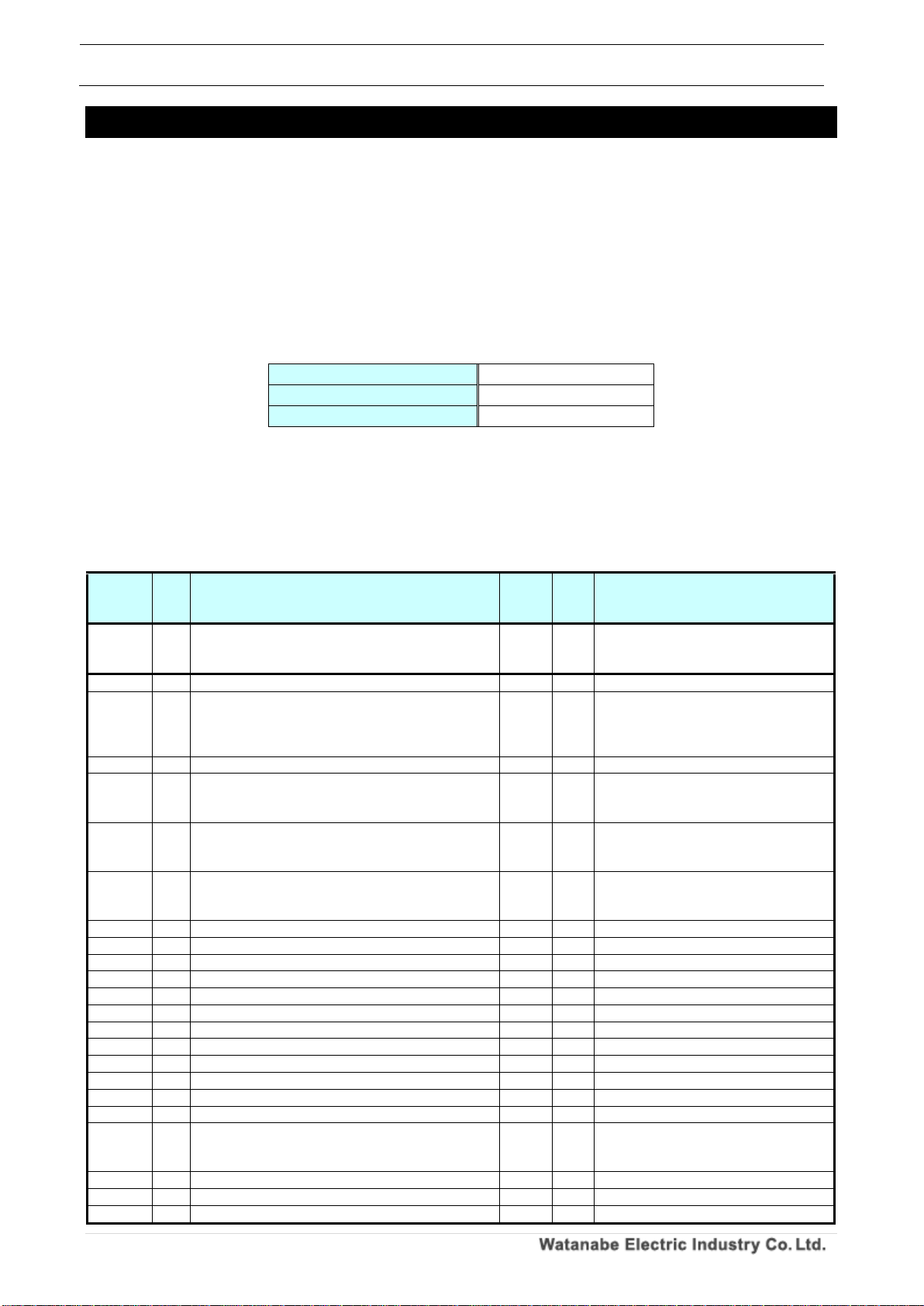
5-1-1. Setting and control parameters
1. Holding register
The hold register command is shown in the table below.
Table 5.1 Holding register command
Read command
03H
Write command
06H
Continuous write command
10H
Con t r ol p a ram e ter s
The control parameters are as follows.
Please refer to "4-1-2. Change control parameters" when making mock input / output instruction
from control parameters.
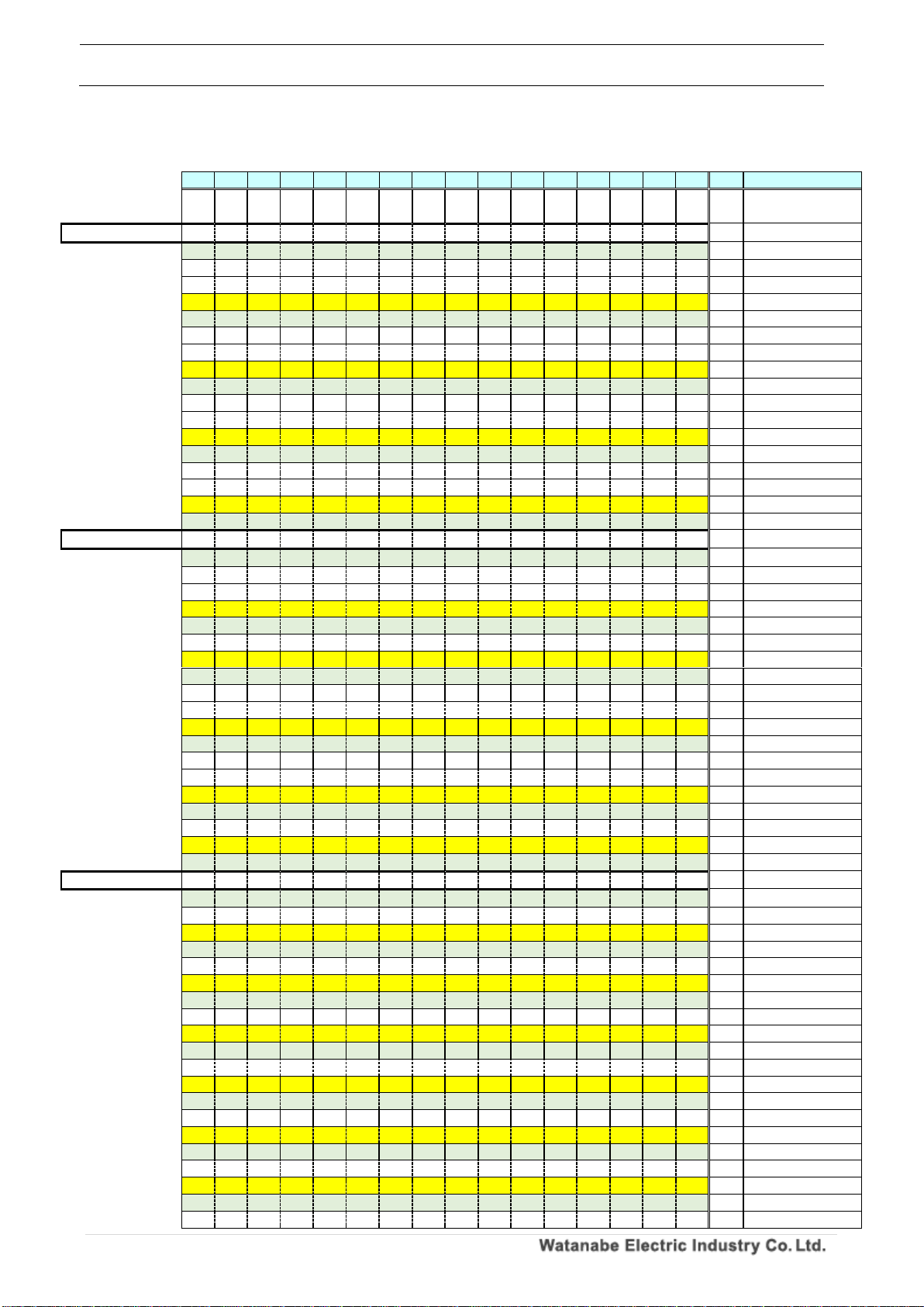
Table 5.2 Control parameters
Communi
cation
address
CH
Contents
size
(byte)
R/W
The data
0000H
~
0065H
~
Reserve
~ ~
0066H
-
Pattern select indication
2
R/W
0000H:Disable、0001H:Enable
0067H
-
Pattern select indication value
2
R/W
0000H:pattern 1、0001H:pattern 2、
0002H:pattern 3、0003H:pattern 4、
0004H:pattern 5、0005H:pattern 6、
0006H:pattern 7、0007H:pattern 8
0068H
-
Relay reset indication
2
R/W
0000H:Disable、0001H:Enable
0069H
-
Integration reset A indication
2
R/W
0000H:Disable、0001H:Enable
※Automatically return to 0000H after
execution
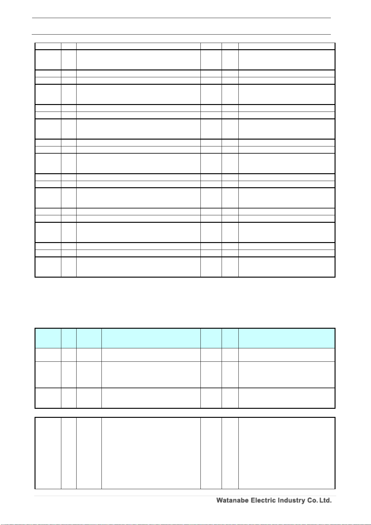
006AH
-
Integration reset B indication
2
R/W
0000H:Disable、0001H:Enable
※Automatically return to 0000H after
execution
006BH
-
Integration reset A & B instruction
2
R/W
0000H:Disable、0001H:Enable
※Automatically return to 0000H after
execution
006CH
-
Measurement prohibited A indication
2
R/W
0000H:Disable、0001H:Enable
006DH
-
Measurement prohibited B indication
2
R/W
0000H:Disable、0001H:Enable
006EH
-
Measurement prohibited A & B indication
2
R/W
0000H:Disable、0001H:Enable
006FH
-
Present value holding A indication
2
R/W
0000H:Disable、0001H:Enable
0070H
-
Present value holding B indication
2
R/W
0000H:Disable、0001H:Enable
0071H
-
Current value holding A & B instruction
2
R/W
0000H:Disable、0001H:Enable
0072H
-
Maximum value holding A indication
2
R/W
0000H:Disable、0001H:Enable
0073H
-
Maximum value holding B indication
2
R/W
0000H:Disable、0001H:Enable
0074H
-
Maximum value holding A & B instruction
2
R/W
0000H:Disable、0001H:Enable
0075H
-
Minimum value holding A indication
2
R/W
0000H:Disable、0001H:Enable
0076H
-
Minimum value holding B indication
2
R/W
0000H:Disable、0001H:Enable
0077H
-
Minimum value holding A & B instruction
2
R/W
0000H:Disable、0001H:Enable
0078H
-
Display switching instruction
2
R/W
0000H:Disable、0001H:Enable
※Automatically return to 0000H after
execution
0079H
-
Trend holding instruction
2
R/W
0000H:Disable、0001H:Enable
007AH
-
Digital zero A instruction
2
R/W
0000H:Disable、0001H:Enable
007BH
-
Digital zero B instruction
2
R/W
0000H:Disable、0001H:Enable
WPMZ Series Modbus communication instruction manual
IM-0862-02
Number of pages:109
27
007CH
-
Digital zero A & B instruction
2
R/W
0000H:Disable、0001H:Enable
007DH
~
03E7H
~
Reserve
~ ~
03E8H
AL1
Compare output instruction
2
R/W
0000H:Disable、0001H:Enable
03E9H
AL1
Comparative output indication value
2
R/W
0000H:OFF、0001H:ON
03EAH
~
0419H
~
Reserve
~ ~
041AH
AL2
Compare output instruction
2
R/W
※AL1 reference
041BH
AL2
Comparative output indication value
2
R/W
※AL1 reference
041CH
~
044BH
~
Reserve
~ ~
044CH
AL3
Compare output instruction
2
R/W
※AL1 reference
044DH
AL3
Comparative output indication value
2
R/W
※AL1 reference
044EH
~
047DH
~
Reserve
~ ~
047EH
AL4
Compare output instruction
2
R/W
※AL1 reference
047FH
AL4
Comparative output indication value
2
R/W
※AL1 reference
0480H
~
0513H
~
Reserve
~ ~
0514H
A
Pulse output indication
2
R/W
0000H:Disable、0001H:Enable
0515H
A
Pulse output indication value
2
R/W
0000H:OFF、0001H:ON
0516H
~
0545H
~
Reserve
~ ~
0546H
B
Pulse output indication
2
R/W
※Pulse output A reference
0547H
B
Pulse output indication value
2
R/W
※Pulse output A reference
0548H
~
0BB7H
~
Reserve
~ ~
Sett i ng p aram e ter s
The setting parameters are as follows.
Refer to "4-1-3. Change setting parameters" when changing the setting parameters.
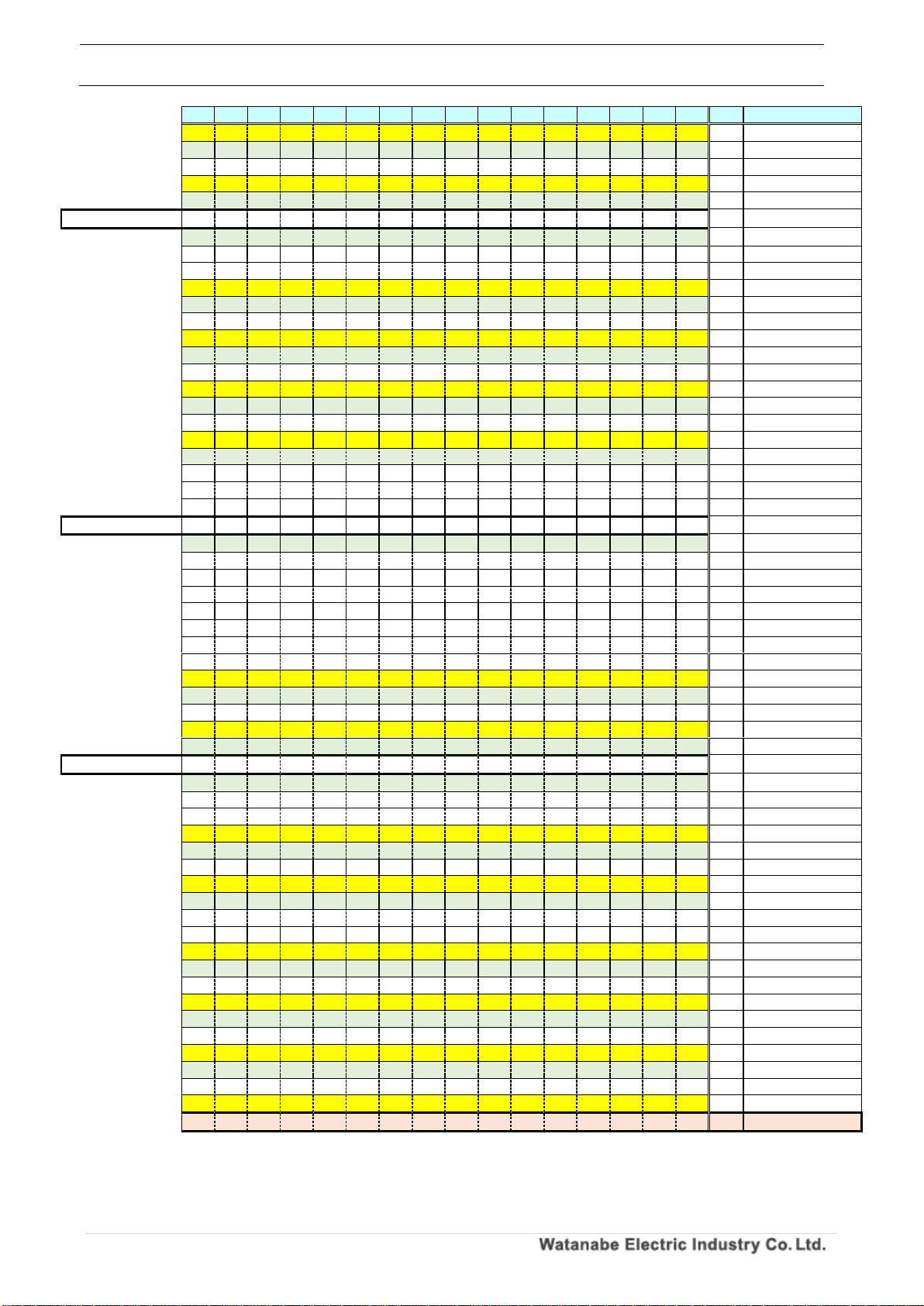
Table 5.3 Setting parameters
Communi
cation
address
CH
Pattern
Contents
size
(byte)
R/W
The data
0BB8H - -
Setting permission / save instruction
4
W
3333 CCCCH:Setting permission、
0000 0000H:Save instruction
0BBAH - -
Setting error contents
2
R
0000H: No error,
Other than 0000H: There is an error
※Error code Refer to "Table 5.4 reference
" for details
0BBBH
~
0BC1H
~ ~ Reserve
~ ~
-
0BC2H A 1
Pulse Input, input type
2
R/W
In case of general purpose pulse input type
0000H:Open collector、
0001H:Logic、
0002H: Zero cross,
0003 H: 2 Wire,
0004H: 2-PhaseOpen Collector * 1, 2,
0005H: 2-Phase Logic * 1, 2,
0006H: 2-Phase 2 Wire* 1, 2
In case of line driver pulse input type
0000H:Line driver
*1 It can not be set when the input B

WPMZ Series Modbus communication instruction manual
IM-0862-02
Number of pages:109
28
model is "None".
*2 It can be set only when the series
model is "WPMZ - 6" and both input type
of A/B are [general purpose pulse input].
0BC3H A 1
Pulse input, input filter
2
R/W
In case of general purpose pulse input type
0000H: None, 0001H: 30 Hz,
0002 H: 1.5 kHz, 0003 H: 15 kHz
In case of line driver pulse input type
0000H: No filter
0BC4H A 1
Sensor power supply for general purpose
pulse input type
2
R/W
0000H:12V、0001H:24V
0BC5H A 1
Sensor power supply for line driver input
type
2
R/W
0000H:5V
0BC6H A 1
Pulse input, mantissa part of instantaneous
value display coefficient
4
R/W
0~999,999
0BC8H A 1
Pulse input, exponent part of instantaneous
value display coefficient
2
R/W
-9~9
0BC9H A 1
Pulse input, instantaneous unit time.
2
R/W
0000 H: Second,
0001 H: Minute,
0002 H: Hour
0BCAH A 1
Pulse input, instantaneous value Decimal
point position
2
R/W
0000H:None,
0001H:The lower right of the 2nd digit,
0002H:The lower right of the 3rd digit,
0003H:The lower right of the 4th digit,
0004H:The lower right of the 5th digit,
0005H:The lower right of the 6th digit
0BCBH A 1
Pulse input, instantaneous value display unit
2
R/W
0000H:None、
0002H:mA、
0004H:kA、
0006H:mV、
0008H:kV、
000AH:W、
000CH:MW、
000EH:mm、
0010H:m、
0012H:kΩ、
0014H:g、
0016H:N、
0018H:MN、
001AH:khan、
001CH:hPa、
001EH:kJ、
0020H:Hz、
0022H:MHz、
0024H:mm/s、
0026H:cm/min、
0028H:m/min、
002AH:m/s2、
002CH:m3/min、
002EH:kg/h、
0030H:kg/m3、
0032H:ℓ、
0034H:ℓ/min、
0036H:%、
0038H:%RH、
003AH:ph、
003CH:rpm、
003EH:inch、
0001H:µA、
0003H:A、
0005H:µV、
0007H:V、
0009H:VA、
000BH:kW、
000DH:µm、
000FH:cm、
0011H:Ω、
0013H:MΩ、
0015H:kg、
0017H:kN、
0019H:Pa、
001BH:Mpa、
001DH:J、
001FH:MJ、
0021H:kHz、
0023H:m3、
0025H:mm/min、
0027H:m/s、
0029H:m/h
002BH:m3/s、
002DH:m3/h、
002FH:kg/m2、
0031H:N/m2、
0033H:ℓ/s、
0035H:ℓ/h、
0037H:‰、
0039H:℃、
003BH:ppm、
003DH:t、
003FH:Custom unit
0BCCH A 1
Pulse input, instantaneous value display
Custom unit 1st character
2
R/W
0000H:None、
0002H:b、
0004H:d、
0006H:f、
0008H:h、
000AH:j、
000CH:l、
000EH:n、
0010H:p、
0012H:r、
0014H:t、
0001H:a、
0003H:c、
0005H:e、
0007H:g、
0009H:i、
000BH:k、
000DH:m、
000FH:o、
0011H:q、
0013H:s、
0015H:u、

WPMZ Series Modbus communication instruction manual
IM-0862-02
Number of pages:109
29
0016H:v、
0018H:x、
001AH:z、
001CH:B、
001EH:D、
0020H:F、
0022H:H、
0024H:J、
0026H:L、
0028H:N、
002AH:P、
002CH:R、
002EH:T、
0030H:V、
0032H:X、
0034H:Z、
0036H:]、
0038H:)、
003AH:2、
003CH:1、
003EH:3、
0040H:µ、
0042H:g、
0044H:/、
0046H:%、
0048H:°、
004AH:”
0017H:w、
0019H:y、
001BH:A、
001DH:C、
001FH:E、
0021H:G、
0023H:I、
0025H:K、
0027H:M、
0029H:O
002BH:Q、
002DH:S、
002FH:U、
0031H:W、
0033H:Y、
0035H:[、
0037H:(、
0039H:1、
003BH:3、
003DH:2、
003FH:-、
0041H:Ω、
0043H:・、
0045H:ℓ、
0047H:‰、
0049H:’、
0BCDH A 1
Pulse input, instantaneous value display
Custom unit 2nd character
2
R/W
※Refer to "Pulse input, instantaneous
value display custom unit first character"
0BCEH A 1
Pulse input, instantaneous value display
Custom unit 3rd character
2
R/W
※Refer to "Pulse input, instantaneous
value display custom unit first character"
0BCFH A 1
Pulse input, instantaneous value display
Custom unit 4th character
2
R/W
※Refer to "Pulse input, instantaneous
value display custom unit first character"
0BD0H A 1
Pulse input, instantaneous value display
Custom unit 5th character
2
R/W
※Refer to "Pulse input, instantaneous
value display custom unit first character"
0BD1H A 1
Pulse input, instantaneous value display
Custom unit 6th character
2
R/W
※Refer to "Pulse input, instantaneous
value display custom unit first character"
0BD2H A 1
Pulse input, instantaneous value auto zero
time
2
R/W
0~9999[×0.01 Seconds]
0BD3H A 1
Pulse input, instantaneous value moving
average
2
R/W
0000 H: None, 0001 H: 2 times,
0002 H: 3 times, 0003 H: 4 times,
0004 H: 5 times, 0005 H: 6 times,
0006 H: 7 times, 0007 H: 8 times,
0008 H: 9 times
0BD4H A 1
Pulse input, instantaneous value simple
average
2
R/W
0000 H: None, 0001 H: 2 times,
0002 H: 4 times, 0003 H: 8 times,
0004 H: 16 times, 0005 H: 32 times,
0006 H: 64 times, 0007 H: 128 times,
0008 H: 256 times
0BD5H A 1
Pulse input, instantaneous value display
step
2
R/W
0000H: None, 0001H: 5 steps,
0002H: 10 steps
0BD6H A 1
Pulse input, mantissa part of totalized value
display coefficient
4
R/W
0~999,999
0BD8H A 1
Pulse input, mantissa part of totalized value
display value coefficient
2
R/W
-9~9
0BD9H A 1
Pulse input, mantissa part of totalized value
default value
4
R/W
-999,999~999,999
0BDBH A 1
Pulse input, exponent part of totalized value
default value
2
R/W
-9~9
0BDCH A 1
Pulse input, total calculation direction
2
R/W
0000H: AddToDefault,
0001H: SubFromDefault
0BDDH A 1
Pulse input, totalized value Decimal point
position
2
R/W
0000H:None,
0001H:The lower right of the 2nd digit,
0002H:The lower right of the 3rd digit,
0003H:The lower right of the 4th digit,
0004H:The lower right of the 5th digit,
0005H:The lower right of the 6th digit
0BDEH A 1
Pulse input, totalized value display unit
2
R/W
※Refer to "Pulse input, instantaneous
value display unit"
 Loading...