

WATANABE A5000 Series Instruction Manual

1.Before Using the Product
Thank you for purchasing the A5000 series. This manual should be passed on to
the person who operates the product. Examine the product for damage caused by
transportation or any other defects. If you find any damage or defects, contact the
sales agent from which you purchased the product or Watanabe Electric
Industry Co., Ltd.
1.1.Model Codes
The model lineup of the A5000 series is shown below. Check that the model
code and specifications of your product match those you specified when
ordering.
2.Mounting the Product
2.1.Dimensions for Cutting Panel
Cut the panel for mounting according to the following dimensions.
2.2.Mounting the Product to the Panel
To mount the A5000 to the panel, remove its fittings and insert it through the
hole in the front of the panel. From the back of the panel, fix the product to the
panel with the fittings.
Instruction Manual for A5000 Series 1/12
UU-33554t
2015.12
MODEL A5000 SERIES
INSTRUCTION MANUAL
(1) Do not apply a voltage or current exceeding the maximum allowable
value; otherwise, it may damage the equipment.
(2)
Use a power voltage within the operation range; otherwise, it may result
in a fire, electrical shock, or malfunction.
(3) The contents of this manual are subject to change without notice.
Although the contents of this manual have been prepared with extra
care, if you have any questions, or find errors or missing information,
contact the sales agent from which you purchased the product or
Watanabe Electric Industry Co.,Ltd.
(4)
After reading this manual thoroughly, keep it in a convenient place for
future reference.
(5)
Caution
!
The mark on a label shows the measurement tail range of the input
specification of 8.1. clause.
(6)
01: DC voltage measuring unit
03: DC current measuring unit
02: DC voltage measuring unit
04: AC voltage measuring unit (average rms)
(range 11: ±99.99 mV)
(range 12: ±999.9 mV ; range 13: ±9.999 V)
(range 23: ±9.999 mA; range 24: ±99.99 mA)
(range 11: 99.99 mV; range 12: 999.9 mV)
05: AC voltage measuring unit (average rms)
(range 14: 99.99 V; range 15: 600 V)
06: AC voltage measuring unit (true rms)
(range 11: 99.99 mV; range 12: 999.9 mV)
07: AC voltage measuring unit (true rms)
(range 14: 99.99 V; range 15: 600 V)
08: AC current measuring unit (average rms)
(range 23: 9.999 mA; range 24: 99.99 mA)
09: AC current measuring unit (average rms)
(range 23: 9.999 mA; range 24: 99.99 mA)
10: AC current measuring unit (true rms)
(range 26: 5 A)
11: AC current measuring unit (true rms)
12: Resistance measuring unit
13: Temperature measuring unit (TC)
14: Temperature measuring unit (RTD)
15: Frequency measuring unit
(inputs: open collector, logic, and magnet)
16: Frequency measuring unit(input: 50 to 500 Vrms)
17: Strain gauze input unit (load cell)
(range 14:±99.99 V ; range 15: ±600 V)
18: Process signal measuring unit (4 to 20 mA or 1 to 5 V)
Input unit
(range 25: ±999.9 mA)
A 5 X X X - X X
(range 13: 9.999 V)
(range 13: 9.999 V)
(range 25: 999.9 mA)
(range 25: 999.9 mA)
(range 26: 5 A)
92
+0.8
-0
45
+0.6
-0
70 mm min.
120 mm min.
WATANABE ELECTRIC INDUSTRY CO., LTD.
0: None
Output unit
1: Comparison
2: Analog
3: RS-232C
4: RS-485
5: Comparison and analog
6: Comparison, analog, and RS-232C
Display unit
1: Single display
2: Multi display
Power unit
1: 100 to 240 V AC ±10%
7: Comparison, analog, and RS-485
A 5 X X X - X X
2: 9 to 60 V DC
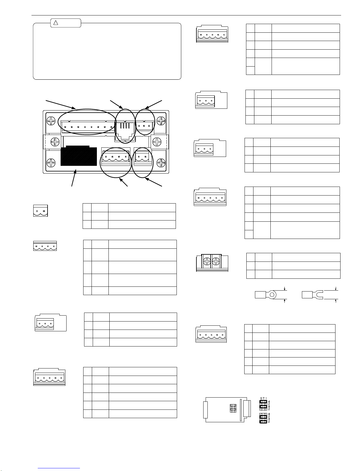
3. Terminal Arrangement
3.1.Power
3.2.External Controls
3.3.Input Signals
3.3.1 DC Voltage Measuring Unit (Range 11)
3.3.2.DC Voltage Measuring Unit (Range 12)
3.3.3. DC Current Measuring Unit
3.3.4. AC Voltage Measuring Unit (Ranges 11 to 13)
3.3.5. AC Voltage Measuring Unit (Ranges 14 and 15)
3.3.6. AC Current Measuring Unit (Ranges 23 to 25)
3.3.7. AC Current Measuring Unit (Range 26)
3.3.8.Resistance Measuring Unit
Instruction Manual for A5000 Series 2/12
(1) Mount the product to a panel that is strong enough to hold the product.
If the panel is not strong enough or the product is not fixed tightly, it
may fall down and cause injury.
(2) The A5000 does not have a power switch, and will thus be immediately
ready for operation upon connecting it to a power supply.
(3) If the product is installed inside other equipment, provide sufficient heat
dissipation to ensure that the temperature inside the equipment does
not exceed 50℃.
Caution
!
External
control
Power
connector
Input (the shape depends on the unit.)
Comparison
output
Serial
communication
Analog output
6 7 8 9 10
1
1
12 13 14 15 16 17 18 19
20
2
1
22
2
3
24 25 26
No. Name Description
10 POWER
Power terminal without polarity for both
DC and AC
11 POWER
Power terminal without polarity for both
DC and AC
10 11
Name Description
6 HOLD
Control for hold function. Enabled when
short-circuited or at the same potential as
COM.
7 DZ
Control for digital zero function. Enabled
when short-circuited or at the same
potential as COM.
6 7 8 9
89PH
COM
No.
Control for peak hold function. Enabled
when short-circuited or at the same
potential as COM.
Common for all external control terminals.
1 2 3
Name Description
1 HI Positive input terminal
2 NC Do not connect this terminal.
3 LO
No.
Negative input terminal
Name Description
1 12
Positive input terminal for range 12
(±999.9 mV)
2 13
3 14
No.
1 2 3 4 5
4 15
5 LO Negative input terminal
Positive input terminal for range 13
(±9.999 V)
Positive input terminal for range 14
(±99.99 V)
Positive input terminal for range 15 (±600
V)
1 2 3 4 5
Name Description
1 23
Positive input terminal for range 23
(±9.999 mA)
2 24
3 25
No.
4
LO5Negative input terminal
Positive input terminal for range 24
(±99.99 mA)
Positive input terminal for range 25
(±999.9 mA)
1 2 3
Name Description
1 11-12
Positive input terminal for ranges 11
(99.99 mV) and 12(999.9 mV)
2 13
3
No.
LO
Positive input terminal for range 13 (9.999 V)
Common input terminal
1 2 3
Name Description
1 14
Positive input terminal for range 14 (99.99 V)
2 15
3
No.
LO
Positive input terminal for range 15 (600 V)
Common input terminal
1 2 3 4 5
Name Description
1 23
Positive input terminal for range 23 (9.999
mA)
2 24
3 25
No.
4
LO5Negative input terminal
Positive input terminal for range 24 (99.99
mA)
Positive input terminal for range 25 (999.9
mA)
5.8
mm
min.
5.8
mm
min.
Applicable solderless terminals
1 2
Name DescriptionNo.
1 HI Input terminal
2 LO Input terminal
1 2 3 4 5
Name Description
1 HI Input terminal for all ranges
2 LO
3 +S
No.
4
COM5
Common terminal (grounding terminal for
input circuit)
Input terminal for all ranges
Constant current for four-wire resistance
measurement(positive)
-S
Constant current for four-wire resistance
measurement(negative)
※Set to the 4-wire system when shipped.
When changing to the 2-wire system, locate
the ST1 socket on the resistance measurement
unit to the “2” positions.
4-wire
2-wire
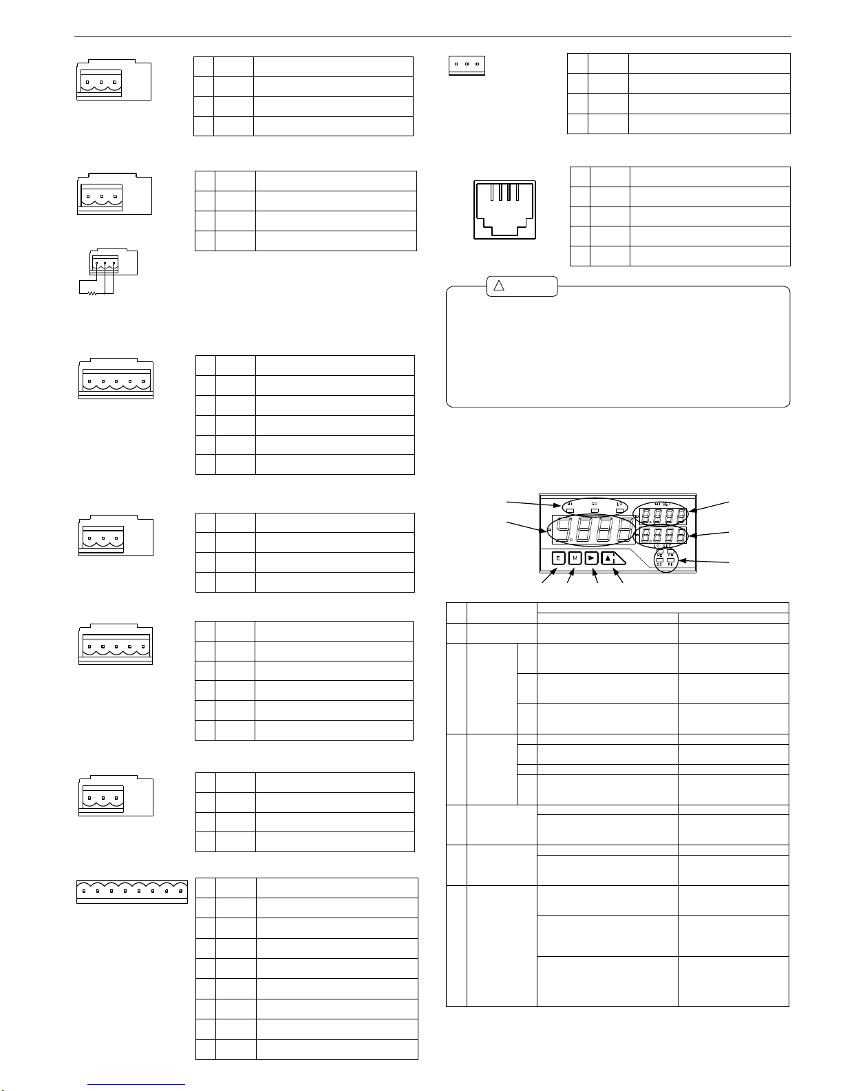
3.3.9. Temperature Measuring Unit (TC)
3.3.10. Temperature Measuring Unit (RTD)
3.3.11. Frequency Measuring Unit (Open collector, logic, and
magnet)
3.3.12.Frequency Measuring Unit (500 Vrms)
3.3.13. Strain Gauge Input Unit (Load cell)
3.3.14. Process Signal Measuring Unit
3.4. Comparison Output
3.5. Analog Output
3.6. Serial Communication
4. Components and their Functions
The front panel design of the A5000 series of unit meters differs depending on the
display unit selected. The names and functions of each unit are as shown below.
4.1.Multi-display Unit
Instruction Manual for A5000 Series 3/12
1 2 3
Name Description
1 + Positive terminal for thermocouple
2 NC
3
No.
-
Do not connect this terminal.
Negative terminal for thermocouple
Connection of three-wire sensor
1 2 3
Name Description
1 A Resistance sensor wire
2 B
3
No.
C Elimination of wire resistance
Resistance sensor wire
The analog output at the time of a burnout becomes + side
at the time of A or B disconnection, and is set to 0V or 1V,
and 4mA at the time of C disconnection.
When A or B is disconnection, it is displayed as OL, and when
C is disconnection, it is displayed as ----.
1 2 3 4 5
Name Description
1 HI Positive input terminal
2 LO
3 +15V
No.
4
COM5
Common terminal (grounding terminal for
input circuit)
Negative input terminal
Power output for sensor (positive)
0V Power output for sensor (negative)
1 2 3
Name Description
1 HI Input terminal
2 NC
3
No.
LO
Do not connect this terminal.
Input terminal
1 2 3 4 5
Name Description
1 +SIG Positive input terminal
2 -SIG
3 +EXC
No.
4
COM5
Common terminal (grounding terminal for
input circuit)
Negative input terminal
Power output for sensor (positive)
-EXC Power output for sensor (negative)
1 2 3
Name Description
1 V-IN Positive input terminal for 1 to 5 V range
2 A-IN
3
No.
LO
Positive input terminal for 4 to 20 mA range
Negative input terminal
12 13 14 15 16 17 18 19
Name Description
12 LO-b LO output terminal (b contact)
13 LO-c
14
No.
LO-a
Common terminal for LO output
LO output terminal (a contact)
15 GO-c Common terminal for GO output
16 GO-a
17 HI-b
GO output terminal (a contact)
HI output terminal (b contact)
18 HI-c
19 HI-a
Common terminal for HI output
HI output terminal (a contact)
24 25 26
Name Description
24 COM Common terminal for analog output
25 A-OUT
26
No.
V-OUT
Current output terminal (4 to 20 mA)
Voltage output terminal (1 to 5 V, 0 to 1 V,
and 0 to 10 V)
202122 23
Name Description
20 RXD(+)
RS-232C: transmission;
RS-485: Non-reverse output
21 TXD(-)
22
No.
NC
RS-232C: reception;
RS-485: Reverse output
Do not connect this terminal.
23 SG Common terminal for communications
(2)(3)(4)(5)
Modular jack:
RJ-14(6P 4C)
(1) Use 12 to 28 AWG wire for the power, input (except for range 26),
external control, and comparison output connectors.
(2) Tighten the screws for the power, input (except for range 26), external
control, and comparison output connectors to a torque of 0.5 to 0.6 Nm.
(3) Use 16 to 28 AWG wire for the analog output connector.
Tighten the screws of analog output connector to a torque of 0.22 to
0.25 Nm.
(4)
Caution
!
Each wiring except a power supply is given as under full-length 30m.
(5)
If 30m is exceeded, it will become out of the scope of EN/IEC standard.
(1)
(2)
(3)
(4)
(6) (7) (8) (9)
(5)
No. Name
Main Functions
During measurement During parameter setup
(1) Main display Indicates the measured value.
IIndicates information on the
parameter to be set.
Judgment
indicators
HI
(2) GO
LO
Indicates the result of judgment and
turns on if the measured value > HI
judgment value.
Indicates the result of judgment and
turns on if LO judgment value ≦ the
measured value ≦ HI judgment value.
Indicates the result of judgment and
turns on if the measured value < LO
judgment value.
(3)
Function
indicators
ME Turns on if “digital zero backup” is on.
PH
Turns on if “peak hold/valley
hold/peak - valley hold” is on.
Turns on if “digital zero” is on.DZ
RE
Turns on if remote control is being
performed through RS-232C or RS485 interface.
(4) Sub-display 1
Indicates the HI side judgment value.
Indicates the item in the
maximum/minimum/(maximumminimum)/input value monitoring mode.
Indicates the LO side judgment value.
Sub-display 2(5)
Indicates information on the item in
the maximum/minimum/(maximumminimum)/input value monitoring mode.
Indicates the item to be set.
(6) Enter key
Pressing the Enter and Mode keys
together changes to the parameter
setting mode.
Pressing the Enter and Increment keys
together changes to the
maximum/minimum/(maximumminimum)/input value monitoring mode.
Switches from the
maximum/minimum/(maximummaximum/minimum/(maximumminimum)/input value monitoring mode to
the comparative judgment reading mode.
Returns to the measurement
mode.
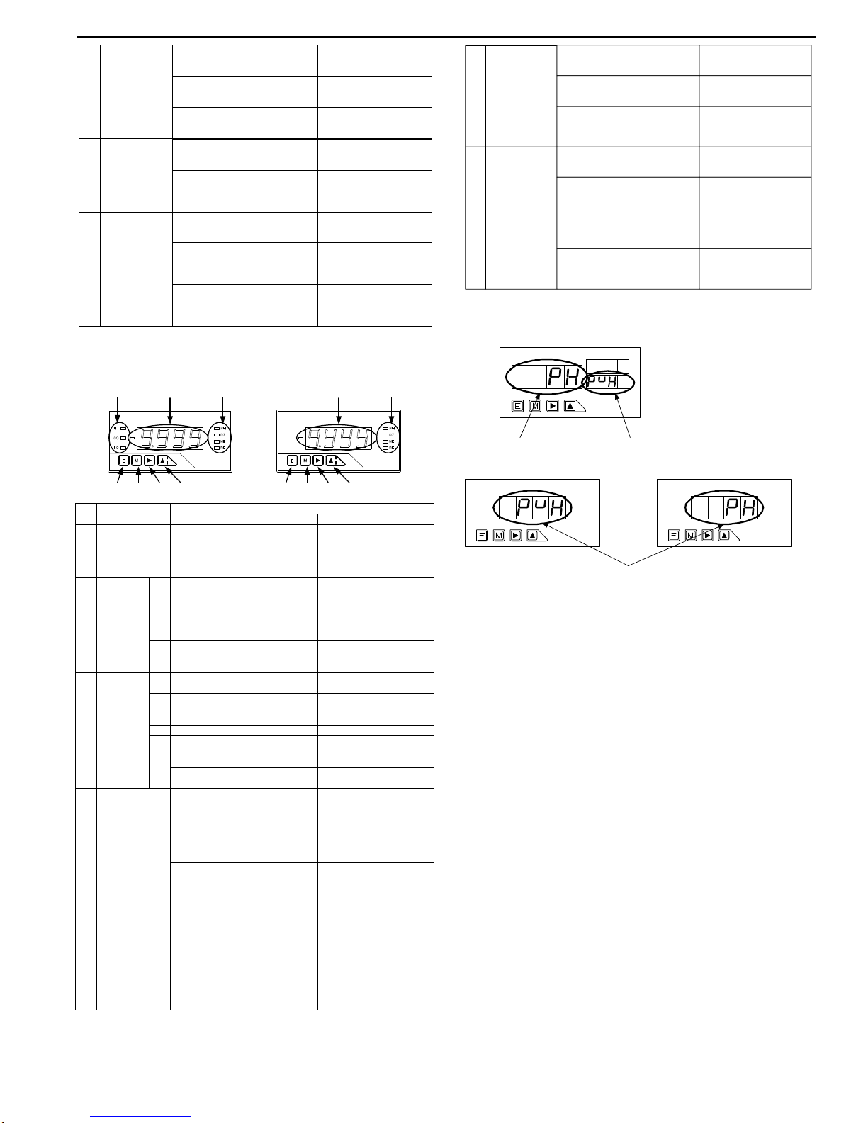
4.2. Single Display Unit
5. Parameter Setup
5.1. Differences between Display Units
5.1.1.Multi-display Unit
Note: Pressing the Mode key displays the next parameter.
5.1.2.Single Display Unit
Note 1: Pressing the mode key with the parameter name shown changes the
display to the parameter information indication. If there is no key
operation for about one second when the parameter name is shown, the
display automatically changes to the parameter information indication
(however, this change does not automatically occur for parameters
PH/S-HI/FSC, etc., right after COND/COM/MET is indicated).
Note 2: Pressing the Mode key when the parameter information indication is
shown results in the next parameter being displayed.
Note 3: If there is no key operation for about 8 seconds with the parameter
information indication shown, the display returns to the parameter
name indication.
Mode key(7)
Pressing the Mode and Enter keys
together changes to the parameter
setting mode.
Selects the item to be set.
Pressing the Mode and Shift keys
together changes to the shift function
setup mode.
Pressing the Mode and Incremental
keys together turns on/off the “Digital
zero” indicator.
(8) Shift key
Pressing the Shift and Mode keys
together changes to the shift function
setup mode.
Selects from items in the
maximum/minimum/(maximumminimum)/input value monitoring mode.
(Hold down the key for about one second.)
Increment key(9)
Pressing the Increment and Mode keys
together turns on/off the “Digital
zero” indicator.
Pressing the Increment and Enter keys
changes to the
maximum/minimum/(maximumminimum)/input value monitoring mode.
Resets the
maximum/minimum/(maximumminimum)/input value monitoring mode.
(Hold down the key for about one second.)
Changes the value or content
of a selected digit.
(Increments the value)
(3) (1) (3)
(6) (7) (8) (9)
No. Name
Main Functions
During measurement During parameter setup
(1) Main display
Indicates the measured value.
IIndicates information on the
parameter to be set.
Indicates information on the item in
the maximum/minimum/(maximumminimum)/input value monitoring mode.
Judgment
indicators
HI
(2) GO
LO
Indicates the result of judgment and
turns on if the measured value > HI
judgment value.
Indicates the result of judgment and
turns on if LO judgment value ≦ the
measured value ≦ HI judgment value.
Indicates the result of judgment and
turns on if the measured value < LO
judgment value.
(3)
Function
indicators
ME Turns on if “digital zero backup” is on.
PH
Turns on if “peak hold/valley
hold/peak - valley hold” is on.
Turns on if “digital zero” is on.
DZ
RE
Turns on if remote control is being
performed through RS-232C or RS485 interface.
Flashes when linearization data output
values are set.
Flashes when linearization data input
values are set.
(6) Enter key
Pressing the Mode and Enter keys
together changes to the parameter
setting mode.
Pressing the Enter and Increment keys
together changes to the
maximum/minimum/(maximumminimum)/input value monitoring mode.
Switches from the
maximum/minimum/(maximummaximum/minimum/(maximumminimum)/input value monitoring mode to
the comparative judgment reading mode.
Returns to the measurement
mode.
Mode key(7)
Pressing the Mode and Enter keys
together changes to the parameter
setting mode.
Selects the item to be set.
Pressing the Mode and Shift keys
together changes to the shift function
setup mode.
Pressing the Mode and Incremental
keys together turns on/off the “Digital
zero” indicator.
(1)(2)
(6) (7) (8) (9)
Setup contents Parameter name
Setup contents and parameter name
(8) Shift key
Pressing the Shift and Mode keys
together changes to the shift function
setup mode.
Selects from items in the
maximum/minimum/(maximumminimum)/input value monitoring mode.
(Hold down the key for about one second.)
Holding down the Shift key for about
one second moves to the HI judgment
value indicator.
Increment key(9)
Pressing the Increment and Mode keys
together turns on/off the “Digital
zero” indicator.
Pressing the Increment and Enter keys
changes to the
maximum/minimum/(maximumminimum)/input value monitoring mode.
Resets the
maximum/minimum/(maximumminimum)/input value monitoring mode.
(Hold down the key for about one second.)
Changes the value or content
of a selected digit.
(Increments the value)
Holding down the Increment key for
about one second moves to the LO
judgment value indicator.
Instruction Manual for A5000 Series 4/12
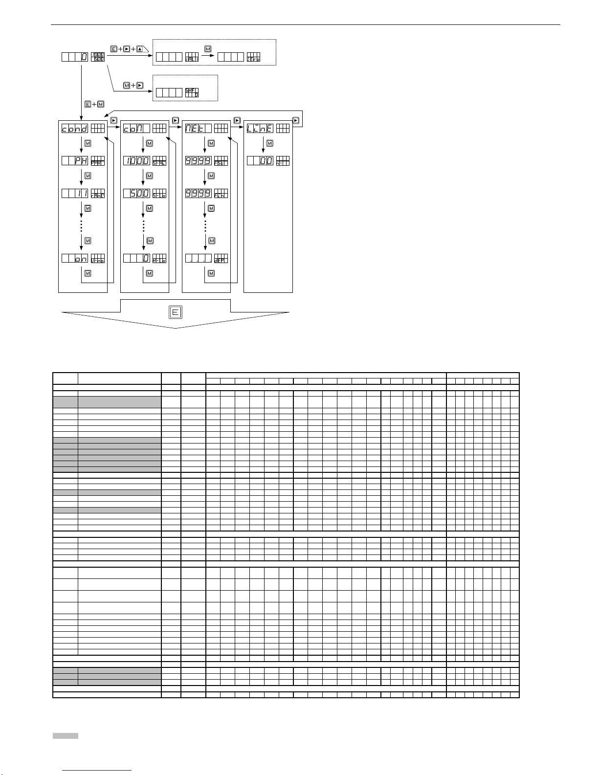
5.2. Moving to the Parameter Setup Mode
5.3. Data Lists and Default Settings
Condition data Comparator data Scaling data Linearization data
Measurement
Pressing the ENTER key saves the data and returns to the measurement mode.
Calibration data
Shift data
(Data are backed up with EEPROM even when the power is turned off.)
Instruction Manual for A5000 Series 5/12
Default Equipped
Indication Name value as 01 02 03 04 05 06 07 08 09 10 11 12 13 14 15 16 17 18 0 1 2 3 4 5 6 7
PVH Peak hold setup PH ○
RANG Measurement range setup *1 × ○ ○ ○ ○ ○ ○ ○ × ○ × ○ ○ ○ ○ ○ × ○
11 15 25 13 15 13 15 25 26 25 26 14 B JPB 14 14 2A
AVG Number of averaging 1 ○ ○ ○ ○ ○ ○ ○ ○ ○ ○ ○ ○ ○ ○ × × ○ ○
MAV Number of moving averaging setup OFF ○
S.UD Step wide setup 1 ○
BLNK Indication blank setup OFF ○
UNIT Unit setup C × × × × × × × × × × × × ○ ○ × × × ×
BAUD Baud rate setup 9600 × × × ○ ○ × ○ ○
DATA Data length setup 7 × × × ○ ○ × ○ ○
P.BIT Parity bit setup E × × × ○ ○ × ○ ○
S.BIT Stop bit setup 2 × × × ○ ○ × ○ ○
T- Delimiter setup CR.LF × × × ○ ○ × ○ ○
ADR Equipment ID setup 00 × × × × ○ × × ○
A.OUT Analog output setup OFF × × ○ × × ○ ○ ○
B.UP Digital zero backup setup OFF ○
LINE Linearization setup CLR ○
I.SEL Input selection OC × × × × × × × × × × × × × × ○ × × ×
TR T Tracking zeroing time setup 00
○
× ×
TR V Tracking zeroing width setup *2 01
○
× ×
SNSR Sensor power setup 5 × × × × × × × × × × × × × × × × ○ ×
PON Power-on delay setup OFF ○
PRO Protect setup OFF ○
U-NO. Unit number Indication setup ON ○
S-HI HI side judgment value setup 1000 × ○ × × × ○ ○ ○
S-LO LO side judgment value setup 500 × ○ × × × ○ ○ ○
H-HI HI side hysteresis setup 0 × ○ × × × ○ ○ ○
H-LO LO side hysteresis setup 0 × ○ × × × ○ ○ ○
FSC Full scale Indication value setup *1 ○ ○ ○ ○ ○ ○ ○ ○ ○ ○ ○ ○ × × × × × ○
9999 9999 9999 9999 9999 9999 9999 9999 9999 9999 9999 9999 9999
FIN Full scale input value setup *1 ○ ○ ○ ○ ○ ○ ○ ○ ○ ○ ○ ○ × × × × × ○
9999 9999 9999 9999 9999 9999 9999 9999 5000 9999 5000 9999 *3
OFS Offset indication value setup *1 ○ ○ ○ ○ ○ ○ ○ ○ ○ ○ ○ ○ × × × × × ○
0 0 0 0 0 0 0 0 0 0 0 0 0
OIN Offset input value setup *1 ○ ○ ○ ○ ○ ○ ○ ○ ○ ○ ○ ○ × × × × × ○
0 0 0 0 0 0 0 0 0 0 0 0 *4
PS Pre-scaling value setup 1 × × × × × × × × × × × × × × ○ ○ × ×
PPR Frequency division setup 1 × × × × × × × × × × × × × × ○ ○ × ×
DLHI Digital limiter HI value setup 9999 × × × × × × × ×
DLLO Digital limiter LO value setup -9999 × × × × × × × ×
AOHI Analog output HI indication setup 9999 × × ○ × × ○ ○ ○
AOLO Analog output LO indication setup 0 × × ○ × × ○ ○ ○
DEP Decimal point position setup None ○ ○ ○ ○ ○ ○ ○ ○ ○ ○ ○ ○ × × ○ ○ ○ ○
*5 ○
ZERO Zero input value *6 0 × × × × × × × × × × × × × × × × ○ ×
SPIN Span input value *6 2000 × × × × × × × × × × × × × × × × ○ ×
SPAN Span indication 9000 × × × × × × × × × × × × × × × × ○ ×
SHF Shift data setup 0 ○
*1 Each value in the lower part of a cell in the columns on the right is the default value.
*2 Tracking zero width setup parameter is not indicated if the tracking time is set to OFF(0).
*3 5000 for 1 V range and 2000 for 2 A range
*4 1000 for 1 V range and 400 for 2 A range
*5 Linearization data are not set up for the default values.
*6 This value is not indicated if calibration is done using an actual load.
The shaded parts show the parameters that must be set for each unit.
Shift data
Input unit number Output unit number
Linearization data
Calibration data
Condition data
Comparator data
Scaling data
○○○
○
○○○
○
× × × × × × × × × × ×
× × × × × × × × × × ×
5.4. Information on Each Parameter
5.4.1Method of Setting Condition Data
This section shows a typical example of setting the peak hold parameter.
The same method applies to other parameters.
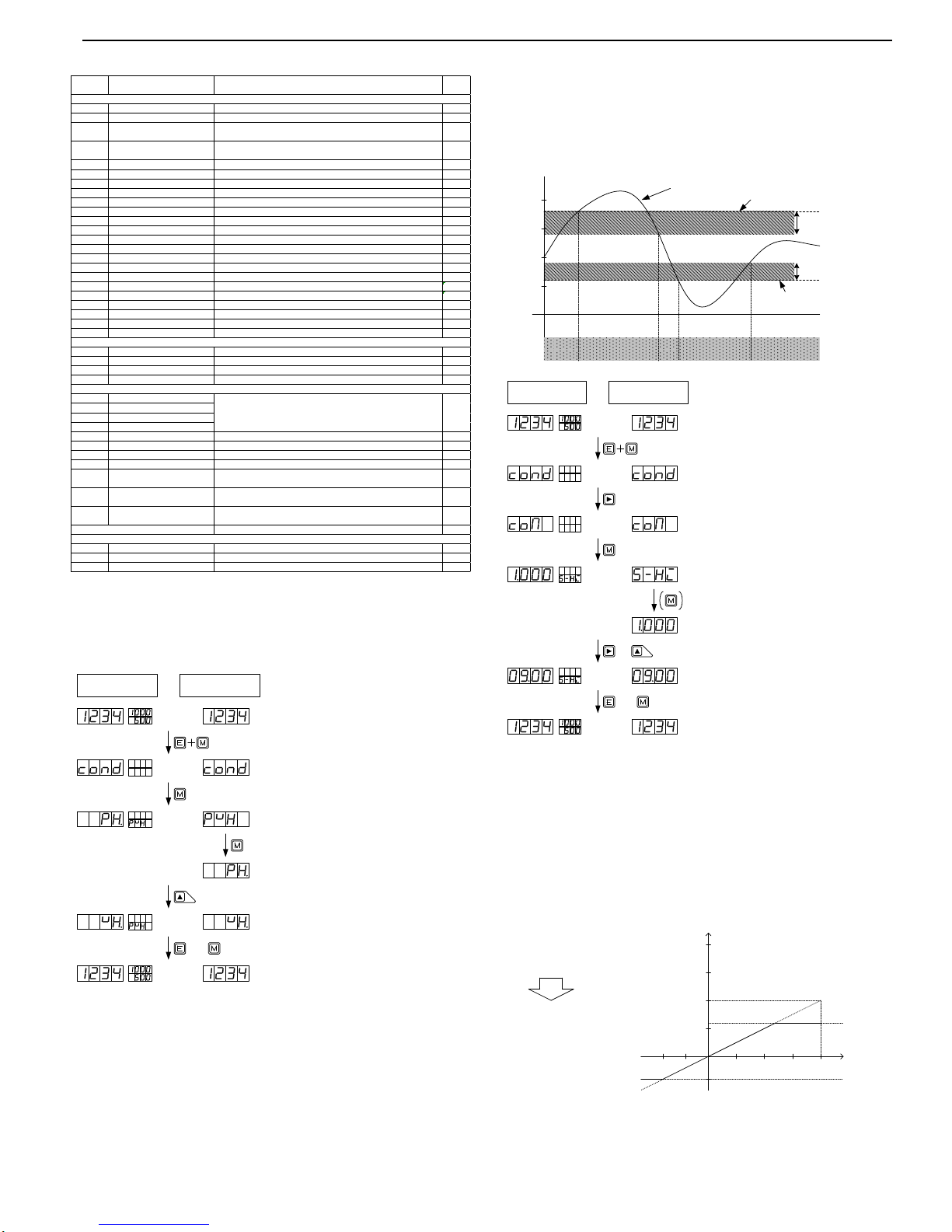
5.4.2 Method of Setting Comparator Data
This section explains comparator data and shows a typical example of setting
the HI side judgment value. The same method applies to all other parameters.
Note: The setup conditions are HI side judgment value > LO side judgment
value, HI side judgment value ³ LO side judgment value + LO side
hysteresis, and LO side judgment value £ HI side judgment value-HI
side hysteresis. If these conditions are not satisfied, an error indication
appears and the display returns to the HI side judgment value setup.
5.4.3 Method of Setting Scaling Data
This section explains comparator data and shows a typical example of setting
the full scale indication parameter. The same method applies to all other
parameters.
Note: For the Digital limiter, values larger than the DLHI setpoint are not
indicated even if signals greater that the value set in the DLHI
parameter are input (for DLLO parameter, values smaller than the
DLLO setpoint are not indicated).
Indication Name Setup options
Default
value
PVH Peak hold setup PH (peak hold)/VH (valley hold)/PVH (peak-valley hold) PH
RANG Measurement range setup *1 *1
AVG
Number of averaging operations
setup
1/2/4/8/10/20/40/80 1
MAV
Number of moving average
operations setup
OFF/2/4/8/16/32 OFF
S.UD Step width setup 1(1digit)/2(2digit)/5(5digit)/0(10digit) 1
BLNK Indication blank setup OFF/B-3/B-2/B-1/ON OFF
UNIT Unit setup C/F C
BAUD Baud rate setup 9600/4800/2400/384(38400)/192(19200) 9600
DATA Data length setup 7(7bit)/8(8bit) 7bit
P.BIT Parity bit setup E (even number), O (odd number), N (none) E
S.BIT Stop bit setup 2(2bit)/1(1bit) 2
T- Delimiter setup CR.LF(CR+LF)/CR CRLF
ADR Equipment ID setup 01 to 99 00
A.OUT Analog output setup OFF/0-1(0 to 1V)/0-10(0 to 10V)/1-5(1 to 5V)/4-20(4 to 20mA) OFF
B.UP Digital zero backup setup OFF/ON OFF
LINE Linearization setup OFF/ON CLR
I.SEL Input selection OC (open collector)/LGC (logic)/MAG (magnet) O.C
TR T Tracking zeroing time setup 00 to 99 00
TR V Tracking zeroing width setup *2 00 to 99 01
SNSR Sensor power setup 10(10V)/5(5V) 5
PON Power on delay time setup OFF/ON OFF
PRO Protect setup OFF/1 to 30 OFF
U-NO. Unit number indication setup OFF/ON ON
S-HI HI side judgment value setup -9999 to 9999 1000
S-LO LO side judgment value setup -9999 to 9999 500
H-HI HI side hysteresis setup 0 to 999 0
H-LO LO side hysteresis setup 0 to 999 0
FSC Full scale indication value setup -9999 to 9999
FIN Full scale input value setup *In the case of AC input, please use it by "+" setting by all means.
OFS Offset indication value setup It is not displayed normally when I use it by "-" setting.
OIN Offset input value setup
PS Pre-scaling value setup 0.001 to 5.000 1.000
PPR Frequency division setup 1 to 100 1
DLHI Digital limiter HI value setup -9999 to 9999 9999
DLLO Digital limiter LO value setup -9999 to 9999 -9999
AOHI
Analog output HI indication
setup
-9999 to 9999 9999
AOLO
Analog output LO indication
setup
-9999 to 9999 0
DEP
Decimal point indication position
setup
None/place of 100/place of 101/place of 102/place of 10
3
None
*2 *2
ZERO Zero input value -0.300 to 2.000 0.000
SPIN Span input value 1.000 to 3.000 2.000
SPAN Span indication 0 to 9999 9000
Condition data
Comparator data
Scaling data
Calibration data
Linearization data
*1
Multi-display unit Single display unit
or
(1) Press the Mode and Enter keys together during
measurement.
(2) Press the Mode key to change to the peak hold
setup mode.
(3) For a single display unit, press the Mode key to
change to the parameter information indication.
(The display automatically changes to this
indication in about 1 second, except right after
COND is indicated.)
(4) Press the Increment key a few times to set to
Valley Hold.
(5) Press the Enter key to return to measurement
mode. (Pressing the Mode key changes to the next
parameter).
HIGO GO LO GO
HI side hysteresis
range
Indicated value
HI side judgment value
LO side judgment value
LO side hysteresis
range
Judgment
900
500
0
1000
300
150
200
HI side judgment value
: 900
HI side hysteresis value
200:
: 300
150:
LO side hysteresis value
LO side judgment value
Multi-display unit Single display unit
or
(1) Press the Mode and Enter keys together during
measurement.
(2) Press the Shift key a few times to display the
comparator data menu.
(6) Press the Enter key to return to the
measurement mode (Pressing the Mode key
changes to the next parameter).
(5) Press the Shift key (change digit) and press the
Increment key (change numeric value) to set to 10.
&
Note:The decimal point in the selected digit
flashes.
(3) Press the Mode key a few times to display the
parameter to be set.
(4) For a single display unit, press the Mode key to
change to the parameter information indication.
(The display automatically changes to this
indication in about 1 second, except for parameter
S-HI right after COM is indicated.)
Indication
Input
5000
10V
Input voltage
: 0 to 10V
0 to 5.000:
Indication
F S C : 5000
F I N : 9999
O F S : 0
O I N : 0
DL H I : 3000
DLLO : -2000
D E P :
The place of 103 is lit.
0
DLLO
DLHI3000
-2000
Instruction Manual for A5000 Series 6/12
 Loading...