

Page 1

W3 POLE INSTALLATION MANUAL
V1.0
Page 2
CONTENTS CONTENTS
W3 POLE INSTALLATION MANUAL
WASSP W3P INSTALLATION MANUAL
The WASSP W3P is an integrated wireless unit for real-time tender mapping within a
portable bracket mounted unit.
The integrated solution, provides transducer, processor, transmitter, position sensors, wifi
and bracket mounted pole in a fully contained and eye catching product.
With a simple bracket mounted attachment, the W3P only requires a power connection
and external PC/Tablet to allow real-time 3D bathymetry mapping of the sea floor from a
vessel which can optionally be transmitted back in real-time to a mothership at distances
up to 2 Nm.
DOCUMENT REVISION HISTORY
W3 POLE INSTALLATION MANUAL
General Notices
WASSP Ltd. reserves the right to change the contents of this manual and any system
specifications without notice.
Contact WASSP Ltd. regarding copying or reproducing this manual.
Support information
If you require maintenance or repair, contact your local dealer. You can also contact
WASSP Ltd. using the following address: wassp.com/support/.
If you need information about WASSP products, visit wassp.com.
On the website you will also find a list of WASSP dealers and distributors.
Warnings, Cautions, and Notes
Warnings, cautions, and notes are indicated by the following icons throughout this
manual:
REVISION DATE REASON FOR CHANGE VERSION
October 2021 Product Release 1.0
RELATED DOCUMENTS
» WASSP DRX Installation Manual – For the latest version of this manual go to
wassp.com
» WASSP Transducer Installation Manual – Installation manual for specific transducers
supported by DRX.
» WASSP CDX Operators Manual – User manual for the WASSP CDX application for
control, visualisation and data post processing of DRX data.
» 3rd Party Application Manuals – 3rd Party Applications that interface with DRX
» Sensor Installation and Operation Manuals – Sensors supported by DRX.
» WASSP DRX ICD – Interface documentation for DRX and associated DRX SDK/API
documentation.
» Sensor Box Installation Manual - Installation Manual for the WASSP Sensor package
Further documentation and updated specifications and DRX installation manual can be
found at wassp.com
CAUTION indicates that if the instruction is not heeded, the action may result
in equipment damage or software corruption.
NOTE indicates a TIP or additional information that could be helpful while
performing a procedure.
»
» 3rd Party Application Manuals – 3rd Party Applications that interface with DRX
» Sensor Installation and Operation Manuals – Sensors supported by DRX.
» WASSP DRX ICD – Interface documentation for DRX and associated DRX SDK/API
documentation.
» Sensor Box Installation Manual - Installation Manual for the WASSP Sensor package
Further documentation and updated specifications and DRX installation manual can be
found at wassp.com
Page 2 of 40 Page 3 of 40Doc: W3 Pole Installation Manual
wassp.com wassp.com
Version: 1.0 October 2021
Doc: W3 Pole Installation Manual
Version: 1.0 October 2021
Page 3

CONTENTS CONTENTS
W3 POLE INSTALLATION MANUAL
W3 POLE INSTALLATION MANUAL
CONTENTS
1 INTRODUCTION 6
1.1. Main Features 6
2 SYSTEM CONFIGURATION 7
2.1. Tender 7
2.2. Mothership 8
3 PART LIST 9
3.1. Standard Supply 9
3.2. Mothership WIFI Equipment WSP-W3-ANT-KIT-MS 9
3.3. Optional Supply 9
3.4. Optional Licenses 10
4 INSTALLATION 11
4.1. Installation Considerations 11
4.1.1. Connect to a Distribution Switchboard 11
4.1.2. Location 11
6.3. Connecting to the W3P via fixed ethernet Cable 20
6.4. Connecting to the W3P via Built in Wifi Router 21
6.5. Networking overview 21
7 INITIAL SETUP - OPERATION 22
7.1. Initial Setup W3P 22
7.1.1. Osets 22
7.1.2. Tide Oset 22
7.1.3. Transducer Draft oset 25
7.1.4. Sound Velocity 26
7.1.5. Roll Oset 27
7.2. Datamanager Overview 27
7.3. Initial Setup Mothership PC 27
8 MAINTENANCE & TROUBLESHOOTING 29
8.1. Maintenance 29
8.2. Replacement of Fuse 30
8.3. Trouble shooting 31
4.2. Installation of the W3P Mounting bracket 12
4.2.1. Installation on a Swim Platform (deck mount) 12
4.2.2. Installation Directly to a Transom 14
5 WIRING 16
5.1. Tender / W3P Pole Side 16
5.1.1. Power Requirement 16
5.1.2. Network Cable Connection 16
5.1.3. PC 16
5.2. Wiring Mothership Side 16
5.2.1. Power Requirement 16
5.2.2. Antenna Mounting 16
5.2.3. Antenna Cabling 17
5.2.4. Bullet Mounting 17
6 INITIAL SETUP - CONNECTING TO SYSTEM 18
6.1. Check Points After Installation 18
6.1.1. Mechanical Checks 18
6.1.2. Turning the Power on and Initial Setup 18
6.2. LED STATUS 18
6.2.1. Startup sequence 19
6.2.2. Normal Operation LED Indications 20
9 NMEA SUPPORTED SENTENCES 32
10 SPECIFICATIONS OF W3P 33
10.1. Outline Drawings 34
10.2. Base Plate Drawings 35
10.3. Bracket Drawings 36
10.4. Interconnection Diagram 38
11 APPENDIX: PRODUCT REGISTRATION, SUPPORT AND RESOURCES 39
FIGURES
Figure 1. System Configuration Tender 7
Figure 2. System Configuration Mothership 8
Figure 3. Mount on transom 13
Figure 4. W3 unit on mount, on transom 13
Figure 5. Bracket showing set angles 15
Figure 6. Loop cable and tie loop with cable ties. 15
Figure 7. Startup Sequence 19
Figure 8. Normal Operation LED Indications 20
Page 4 of 40 Page 5 of 40Doc: W3 Pole Installation Manual
wassp.com wassp.com
Version: 1.0 October 2021
Doc: W3 Pole Installation Manual
Version: 1.0 October 2021
Page 4
CONTENTS CONTENTS
W3 POLE INSTALLATION MANUAL
W3 POLE INSTALLATION MANUAL
1 INTRODUCTION
The WASSP W3P is a ‘All in one’ portable multibeam mapping solution that includes all
the components to make a complete the WASSP Multibeam Sounder System (sans PC).
Conveniently housed in one pole mounted system – this includes DRX processor, Wi-Fi
units (for local and remote access) IMU motion sensor and Satellite compass.
The supplied bracket allows for transom or duck board mounting, and can easily be
set to various angles and heights to accommodate dierent transoms and installation
requirements.
The WASSP W3P system can be configured to operate in various modes, typically using a
wide-angle sonar transducer to profile the water column and seafloor in high resolution.
The WASSP W3P can be configured to be suitable for operations such as Exploration,
survey and mapping, search and rescue and many more.
Actual data types output to client applications, such as WASSP CDX, will be determined
by:
» Data types enabled in DRX, as determined by the licensing model
» Data types the client application supports and queries for
» If the client application is using raw, processed or post processed data
2 SYSTEM CONFIGURATION
NOTE: ALL EQUIPMENT CASES TO BE EARTHED
NOTE: ALL CABLES TO BE SCREENED
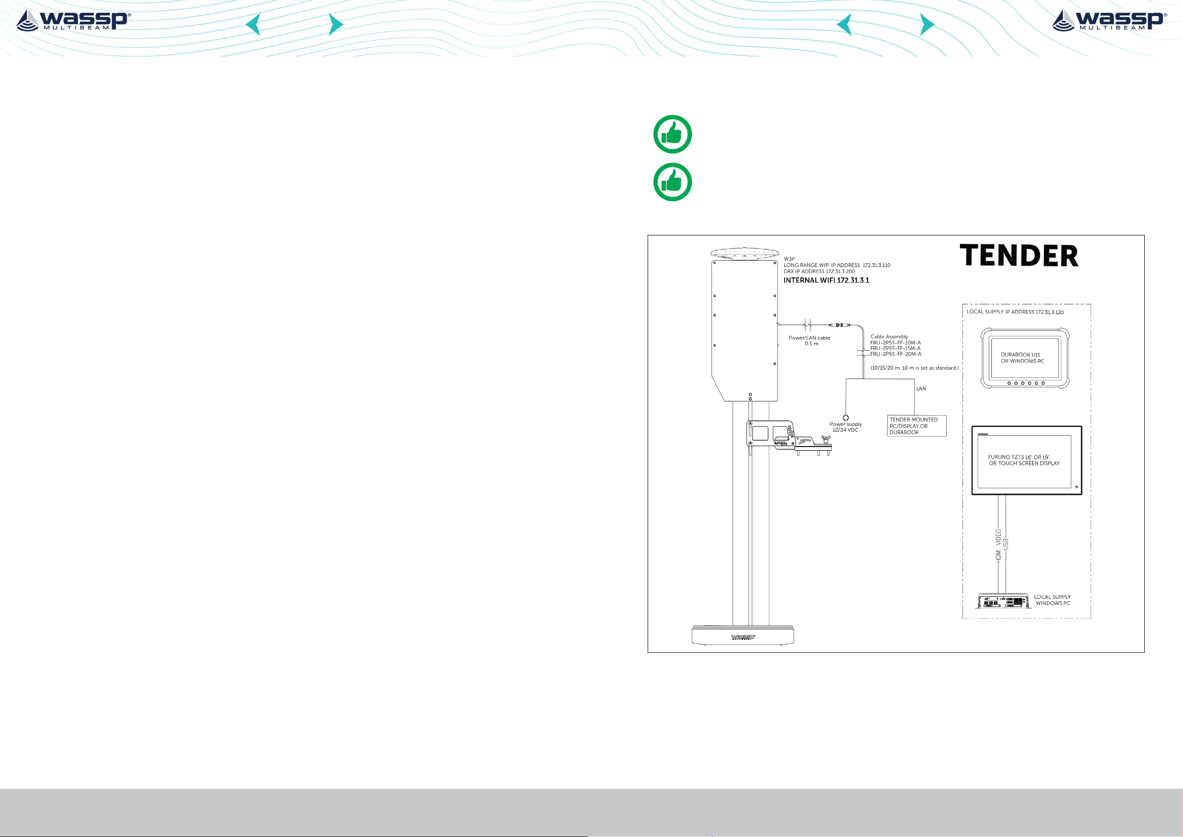
2.1. TENDER
» Data types that are supported will increase through continual product development
and DRX upgrades
The WASSP W3P functionality is defined by the software installed, the data types enabled.
1.1. MAIN FEATURES
The main features of WASSP in a multibeam configuration will depend on the model as
follows:
» 120° Swath coverage
» Up to 2Nm realtime mapping (coverage dependent)
» Designed for (max 15knots) high speed quick deployment mapping
» Store and forward mapping technology for out of range data gathering
» Rugged all in one pole mount design
» 12/24VDC operation
» Control via CDX SW on remote on board PC or Windows tablet
» Depth capability is configuration and environment dependent. Typical numbers are
DRX-32 with WASSP Wideband Fairing Transducer; 1 to 400m
» WMB Fairing Transducer 90-190 khz operation
Figure 1. System Configuration Tender
» WSP IMU038 0.2° pitch/roll accuracy static, .25°dynamic, 5cm or 5% heave
» WSP V200 Sat Compass 0.75° heading accuracy
» Internal 5ghz Wi-Fi router
Page 6 of 40 Page 7 of 40Doc: W3 Pole Installation Manual
wassp.com wassp.com
Version: 1.0 October 2021
Doc: W3 Pole Installation Manual
Version: 1.0 October 2021
Page 5
CONTENTS CONTENTS
W3 POLE INSTALLATION MANUAL
W3 POLE INSTALLATION MANUAL
2.2. MOTHERSHIP
3 PART LIST
3.1. STANDARD SUPPLY
WASSP P/N Qty Name Type Remarks
WFT1320W3P90-190-2.5 1 WASSP W3 POLE W3P
WSP-400-952 1 BRACKET ASSEMBLED W3P BRACKET
WSP-400-912 6 HANDLES
WSP-400-901 1 DECK PLATE
WSP-400-904 2 T SLOT ADAPTER
WSP-400-951 1 BREAKAWAY PIN SHEER PIN FOR BRACKET CONSUMABLE ITEM
001-512-600-00 1 POWER CABLE
WSP-002-216 CDX license WASSP CDX License
WSP-002-210 WASSP License Module Time Zero Interface
CLAMP LEVERS FOR DECK
AND POLE MOUNT
DECK/TRANSOM MOUNT
PLATE
STAINLESS T SLOT FOR
BRACKET TO POLE MOUNT
COMBINED POWER /
ETHERNET CABLE 10M
Required for operation
choose one
Required for operation
choose one’
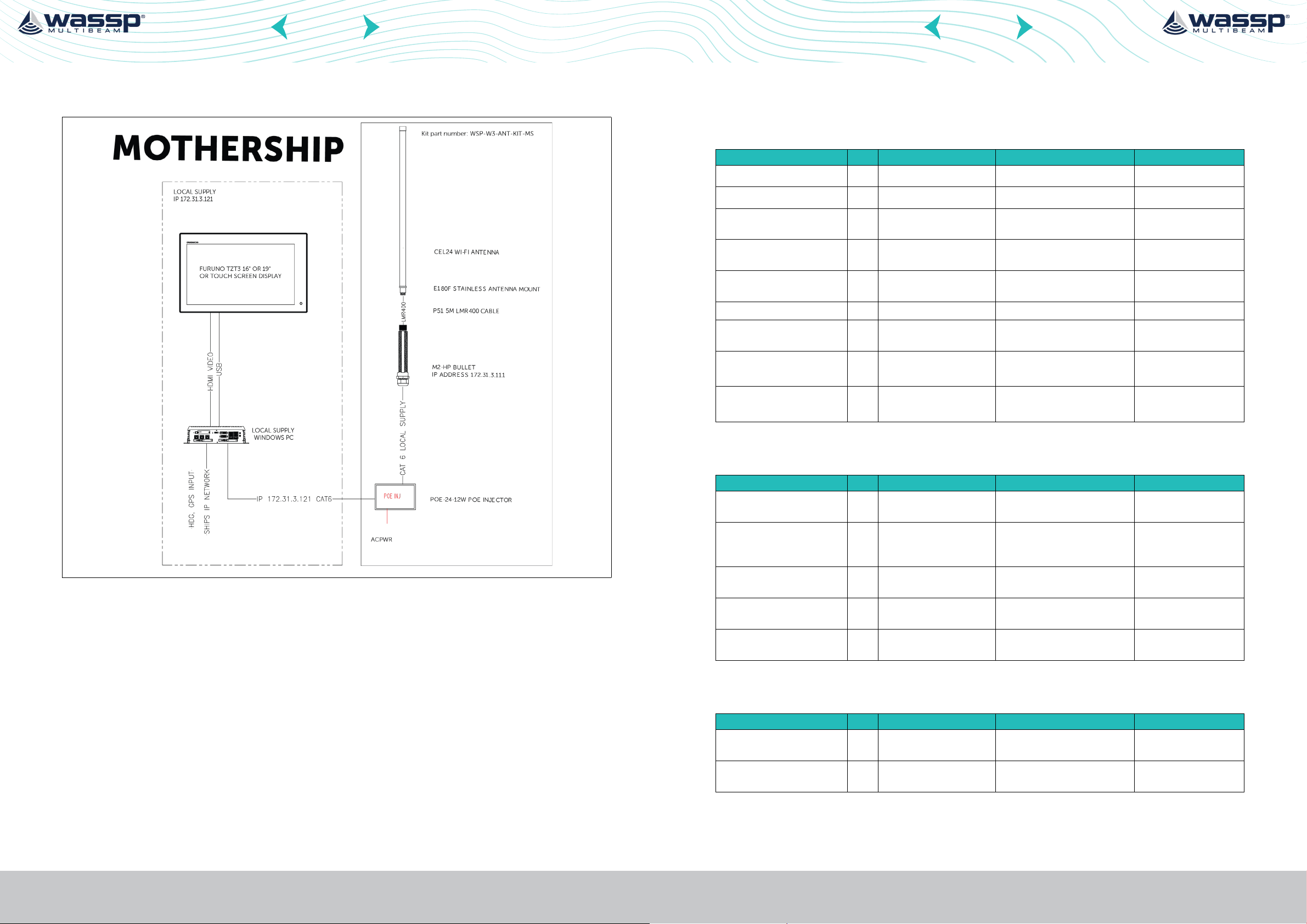
Figure 2. System Configuration Mothership
3.2. MOTHERSHIP WIFI EQUIPMENT WSP-W3-ANT-KIT-MS
WASSP P/N Qty Name Type Remarks
M2 HP 1 WiFI Bullet
CEL24 1 Wifi Antenna
E180F 1 ANTENNA MOUNT
P51 1 ANTENNA CABLE
POE-24-12W 1
MOTHERSHIP AC POE
INJECTOR
802.11b/g/n 600mW
Outdoor AP/Bridge
Omnidirectional Antenna
c/w N240F N-female
Connector (2310-2485 MHz)
Stainless Steel Deck Mount
Flange - 1 1/4" - 11 TPI
N-Male to N-Female 500cm
LLC400 Pig-tail
POE-24-12W 0.5A
airGateway Compatible POE
3.3. OPTIONAL SUPPLY
WASSP P/N Qty Name Type Remarks
001-512-620-00 POWER CABLE COMBINED POWER/
ETHERNET CABLE 15M
001-512-640-00 POWER CABLE COMBINED POWER/
ETHERNET CABLE 20M
Page 8 of 40 Page 9 of 40Doc: W3 Pole Installation Manual
wassp.com wassp.com
Version: 1.0 October 2021
Doc: W3 Pole Installation Manual
Version: 1.0 October 2021
Page 6

CONTENTS CONTENTS
W3 POLE INSTALLATION MANUAL
W3 POLE INSTALLATION MANUAL
3.4. OPTIONAL LICENSES
WASSP P/N Qty Name Type Remarks
WSP-002-210 TZ License TimeZero Pro Inter-face
WSP-002-200 Backscatter License Backscatter License
WSP-002-201 Water Column target
License
WSP-002-202 Side Scan License Side Scan License for tender
WSP-002-300 XYZ Data Format export Datamanager XYZ export
WSP-002-301 GSF Data Format export Datamanager GSF export
WSP-002-209 Survey License Survey functionality, Provides
Fish targets dis-played on
tender only
only
license
license
connection to 3rd party
clients like Hypack, Eiva, &
QPS that require uncorrected
data Included in S3.
Please note Survey
license WSP-002209 must be used in
conjunction
4 INSTALLATION
4.1. INSTALLATION CONSIDERATIONS
4.1.1. Connect to a Distribution Switchboard
» The W3P has a power switch, and should be connected to a fused power switch
board of either 12/24v DC
4.1.2. Location
» Install the pole in a vertical position,
with power cable in the forward
orientation.
Page 10 of 40 Page 11 of 40Doc: W3 Pole Installation Manual
wassp.com wassp.com
Version: 1.0 October 2021
» Install the W3P in a position on the transom the vessel, the pole can be mounted
on to a suitably strong swim platform (or duckboard) the mount can accommodate
fore/aft angles of up to 15° by selecting a location for the shear pin.
Alternatively, the bracket can be rotated to be and mounted against the transom of
the vessel again the bracket can accommodate angles up to 15° for aft.
The mount should be strong enough to not cause the pole to wobble while
underway, or cause damage to the vessel under normal operation, or while kicking
up on the event of striking an object
» The unit should be mounted were the transducer can be lowered into a clean flow
of water away from electrically noisy systems, or items on the vessel that create
turbulent water (i.e water inlets/outlets, engine intakes or exhausts
» The unit should not interfere or come in contact with the vessels drive units (i.e
outboards or sterndrives) and should not be subjected to thrust or forces from the
drive unit (i.e a jet drive)
» Install the pole where the GPS satellite compass on top of the unit has an
Doc: W3 Pole Installation Manual
Version: 1.0 October 2021
Page 7
CONTENTS CONTENTS
22
W3 POLE INSTALLATION MANUAL
unobstructed view of the sky, and is away from VHF transmitters and RADAR
systems that may cause interference
» Install the system where the long range Wi-Fi antenna (mounted inside the case
under the satellite compass at the rear of the unit) is not blocked by metallic object
that could interrupt transmission
» Ensure that the pole can be raised and lowered.
NOTE: The W3P pole is designed with a shear pin that will break if excessive
force is applied to the pole – this is to try to protect the pole in case it strikes
an object. The pole will rotate forward in this instance and it should be in a
position that it will not cause harm to anyone on board.
NOTE: Maximum Speed warning: the unit is designed to be used at a speed
up to 15knots in calm seas, operating at speeds above this could cause
damage or death to persons on board the vessel, damage to the unit, or
damage to the vessel.
W3 POLE INSTALLATION MANUAL
4.2. INSTALLATION OF THE W3P MOUNTING BRACKET
Determine the suitability of the mounting location BEFORE permanently mounting the
sensor.
4.2.1. Installation on a Swim Platform (deck mount)
Mount the deck mount plate WSP-400-901 so the bracket can easily be slid on or o the
transom of the vessel. Use 4 x M10 socket capscrews with suitable washer and nyloc nut,
ensure all surfaces are covered in a corrosion inhibitor such a tef-gel to prevent to metal
to metal corrosion.
The bracket of the W3P can be bolted down to the plate using the supplied Clamp levers
(M8 x 1.25 thread) ensure threads are covered in a corrosion inhibitor such as tef-gel, and
that excessive torque is not applied to the clamp levers. This could damage the threads in
the aluminium mount.
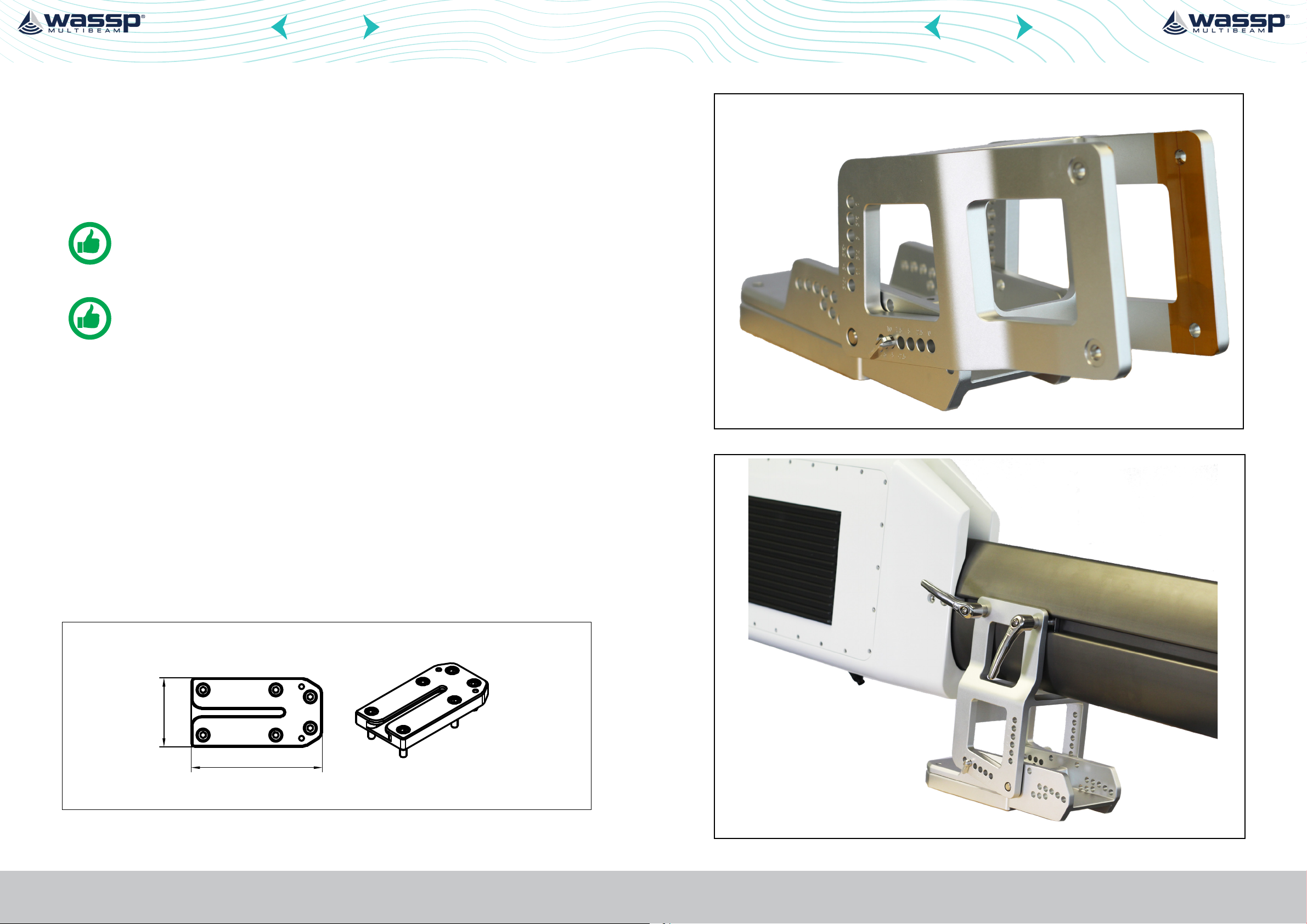
Figure 3. Mount on transom
100
Page 12 of 40 Page 13 of 40Doc: W3 Pole Installation Manual
190
wassp.com wassp.com
Version: 1.0 October 2021
Figure 4. W3 unit on mount, on transom
Doc: W3 Pole Installation Manual
Version: 1.0 October 2021
Page 8
CONTENTS CONTENTS
W3 POLE INSTALLATION MANUAL
4.2.2. Installation Directly to a Transom
» Mount the deck mount plate WSP-400-901 so the opening on the bracket is facing
up.
» Ensure the pole easily be slid on or o the transom of the vessel.
» Use 4 x M10 socket capscrews with suitable washer and nyloc nut, ensure all
surfaces are covered in a corrosion inhibitor such a tef-gel to prevent to metal to
metal corrosion.
» The bracket of the W3P can be bolted down to the plate using the supplied Clamp
levers (M8 x 1.25 thread), alternatively locally sourced bolts may be used.
» Ensure threads are covered in a corrosion inhibitor such as tef-gel, and that
excessive torque is not applied to the clamp levers/bolts. This could damage the
threads in the aluminium mount.
1. Use the supplied plate as a template to the mounting location, then drill four fixing
holes in the mounting location.
W3 POLE INSTALLATION MANUAL
NOTE: The holes must be parallel with the fore and aft line.
2. Put the plate on the platform and ensure that is lined up parallel with the ship’s bow.
3. Use customer furnished bolts, flat washers, spring washer to secure the plate to the
platform/transom. The torque for the bolts is 19.6 to 24.5 N*m
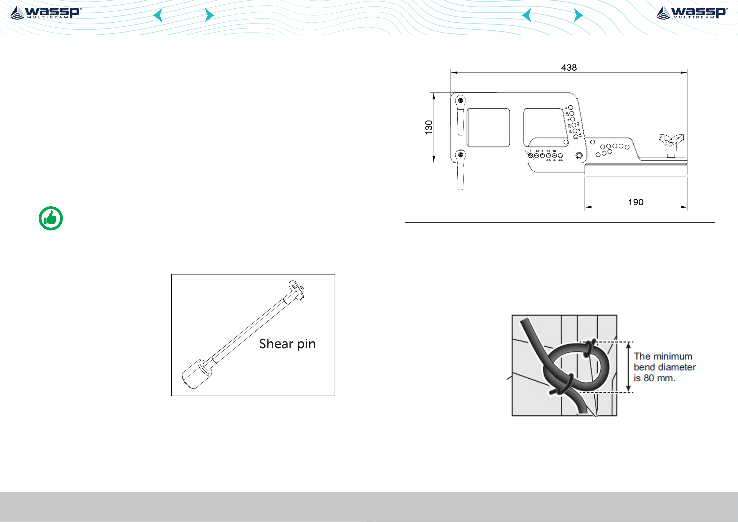
4. Use the bracket shear pin inserted
into a suitable hole so that the
transducer is mounted level on
the transom when at rest.
Figure 5. Bracket showing set angles
5. Connect the power/LAN cable to the cable assembly.
Follow these guidelines for laying the power/LAN cable:
• The connectors must not strike any part of the vessel due to wind, etc.
• Do not apply any load to the connectors
• The cable must
be located where
no tension is
applied to the
connectors. To
prevent tension,
create a loop in
the cable close
to the sensor and
tie the loop with
cable ties
Page 14 of 40 Page 15 of 40Doc: W3 Pole Installation Manual
wassp.com wassp.com
Version: 1.0 October 2021
Figure 6. Loop cable and tie loop with cable ties.
• Ensure that either end of the cable when disconnected cannot be dropped
into water. Cover connector when disconnected and not in use to ensure
that water cannot ingress and cause corrosion.
6. Connect the cable assembly to the power source and display unit. See “5 Wiring” on
page 16.
Doc: W3 Pole Installation Manual
Version: 1.0 October 2021
Page 9

CONTENTS CONTENTS
W3 POLE INSTALLATION MANUAL
W3 POLE INSTALLATION MANUAL
5 WIRING
5.1. TENDER / W3P POLE SIDE
5.1.1. Power Requirement
The W3P requires either 12 VDC or 24 VDC power.
» Connect the red cable to the positive terminal of ship’s battery
» Connect the blue cable to the negative terminal
» The black cable is a shielding cable for grounding
5.1.2. Network Cable Connection
Connect the network cable to the ships furnished windows PC or ships network. See
“Figure 1. System Configuration Tender” on page 7 and “6.3. Connecting to the W3P
via fixed ethernet Cable” on page 20.
If using the internal Wifi directly to the pole (i.e using a Durabook to wirelessly connect
to the pole), please ensure the cable is sealed with self amalgamating rubber tape, and
insulation tape and left in a dry location. See “6.4. Connecting to the W3P via Built in Wifi
Router” on page 21 for connection information.
NOTE: For best performance we recommend using the network cable to
communicate with the DRX.
5.2.3. Antenna Cabling
See “Figure 2. System Configuration Mothership” on page 8.
» Screw the supplied 5m coaxial cable to the N type fitting on the bottom of the
CEL24 antenna, and pass the cable through antenna mount.
» Using the overlocking nut (N239F) and O ring Secure the antenna onto the E180F
base.
NOTE: Wifi performance will be degraded by a long antenna run or poor
cable connection, where possible keep the antenna cable as short as
possible and extend the Ethernet cable to the Wifi bullet.
5.2.4. Bullet Mounting
1. Mount the M2 Bullet HP in a cool dry location. Screw the other end of the coaxial
cable to the Ntype connector.
2. Connect the Cat6 cable (user supplied) into the bottom of the Bullet unit.
3. Connect the Cat6 connected to the bullet to the POE labelled output on the POE
injector. Connect the AC power cable to the POE injector and connect to a local AC
power supply. Connect the second CAT6 cable directly to the ethernet port for the
mothership PC .
4. Set the IP address of the Mothership PC to 172.31.3.121 Subnet 255.255.0.0
5.1.3. PC
Connect PC as per manufactures instructions and Install the WASSP CDX SW (refer CDX
user Manual).
5.2. WIRING MOTHERSHIP SIDE
5.2.1. Power Requirement
The Wireless antenna bullet is designed to powered by the supplied AC powered POE
injector, however it can be powered by a DC powered version or suitable POE network
switch (local supply).
5.2.2. Antenna Mounting
Mount the antenna base with a clear view forward of the vessel, the higher the antenna
the greater the range of the antenna, however if it is too high, the tender may not be able
to connect to the mothership when the are along side. Consideration of high powered
transmitters that may interfere with the wireless access point (other Wifi, VHF, SSB,
RADARS and VSAT/SATCOMMS) should be taken into account, mount the unit away from
sources of interference – consult your dealer for more information.
5. Install the CDX software as per the CDX user manual.
Page 16 of 40 Page 17 of 40Doc: W3 Pole Installation Manual
wassp.com wassp.com
Version: 1.0 October 2021
Doc: W3 Pole Installation Manual
Version: 1.0 October 2021
Page 10

CONTENTS CONTENTS
W3 POLE INSTALLATION MANUAL
W3 POLE INSTALLATION MANUAL
6 INITIAL SETUP - CONNECTING TO SYSTEM
6.1. CHECK POINTS AFTER INSTALLATION
Before using the product, carry out the following:
» Mechanical checks
» Turning the power on and initial setup
6.1.1. Mechanical Checks
Check below points before switching on the W3P.
» All washers are in place and bolts are fully fastened.
» All connections are secure and network cable is connected to the multi function
display
» All connecting cables and wires are secured. See “5 Wiring” on page 16.
6.1.2. Turning the Power on and Initial Setup
Use the information in this manual and the manual for CDX software to power the sensor
and to proceed with initial setup.
» Briefly press the power button on the W3P, all the LEDS will initially turn on.
» To turn OFF the W3P, press and hold the power key for more than 4 seconds. All
LEDs will turn o, indicating that power has been turned o
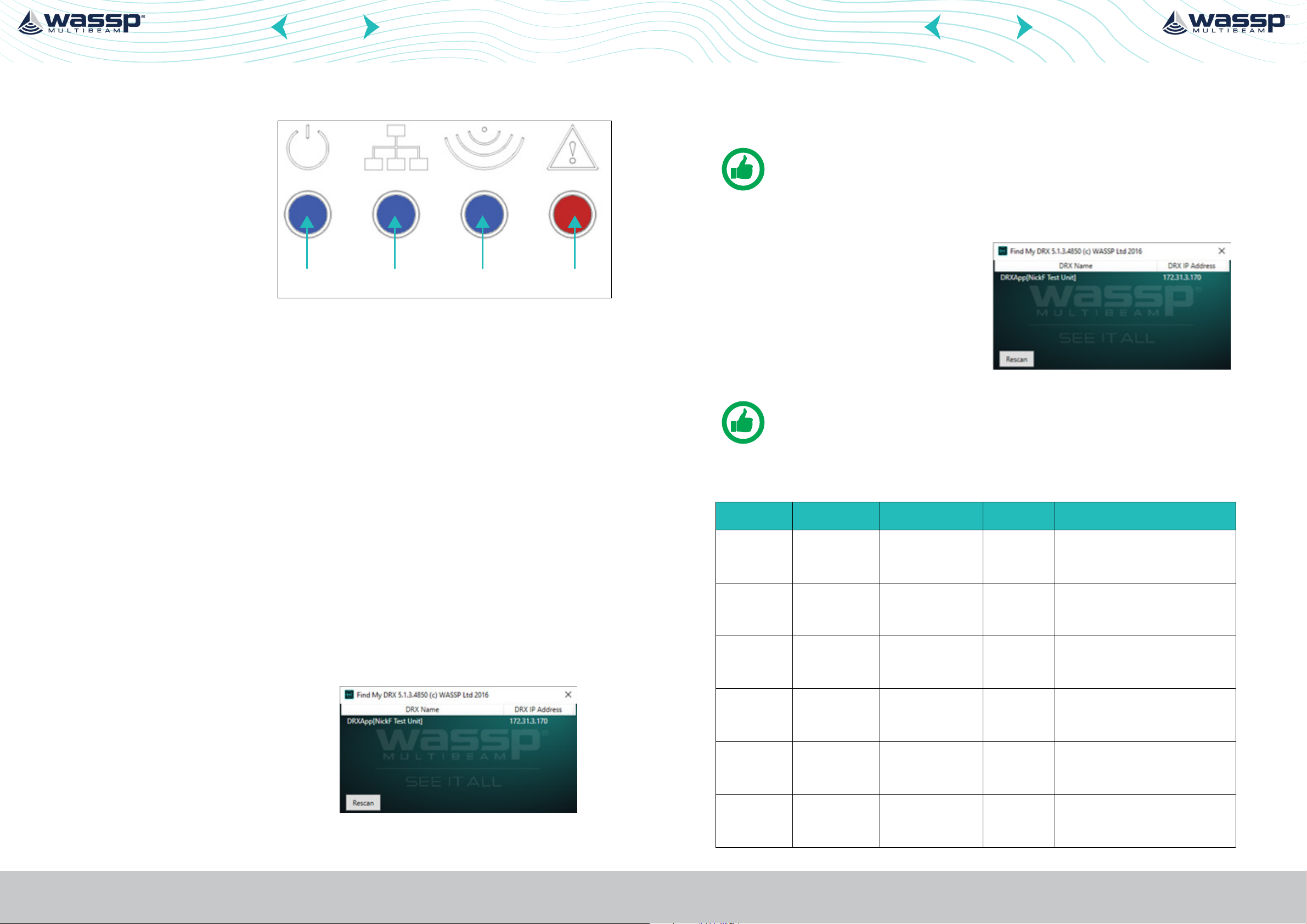
The DRX features 4 LEDS next to the power button which give a quick indication of the
status of the DRX system.
6.2.1. Startup sequence
The boot sequence is as below:
Power on
Booting
Power Network Ping Error
Starting
Process
6.2. LED STATUS
Normal
Operation
Figure 7. Startup Sequence
Page 18 of 40 Page 19 of 40Doc: W3 Pole Installation Manual
wassp.com wassp.com
Version: 1.0 October 2021
Doc: W3 Pole Installation Manual
Version: 1.0 October 2021
Page 11
CONTENTS CONTENTS
W3 POLE INSTALLATION MANUAL
W3 POLE INSTALLATION MANUAL
6.2.2. Normal Operation LED Indications
Power LED:
O = Power OFF
On Solid = DRXApp is running
Network LED:
O: No Link (cable not connected)
Solid: Link/Link Established
Blinking: Tx or RX trac
Ping LED:
O: Not pinging
Blinking: Pinging with frequency relative to ping rate (not actual ping rate).
Error LED:
Power Network Ping Error
Figure 8. Normal Operation LED Indications
6.4. CONNECTING TO THE W3P VIA BUILT IN WIFI ROUTER
1. Scan on the available wireless networks for WASSP_LOCAL
NOTE: This is preset to USA frequencies on the 5ghz band.
2. The Password is WASSP123 (case sensitive).
3. Open the Find My DRX program (refer
CDX operation manual).
4. If connected correctly and powered
on the unit will be found as per the
screenshot.
NOTE: The Built in router will provide an IP address in the correct range,
however we recommend to FIX the IP address to 172.31.3.199 subnet
255.255.0.0
O: Normal operation
On: (While booting) system is booting
On: (After booting) Indicates an error state. All LED states should be noted and reported
to WASSP Support. See “11 Appendix: Product Registration, Support and Resources” on
page 39.
6.3. CONNECTING TO THE W3P VIA FIXED ETHERNET CABLE
Power on the Windows PC or Tablet used on the tender to connect to the W3P pole.
1. Plug in the Rj45 connector to the PC connection.
2. Set the fixed IP address of the LAN port used to talk to the W3P to a Class B IP address
– Suggested address is 172.31.3.120 subnet 255.255.0.0
3. Open the Find My DRX program (refer
CDX operation manual)
4. If connected correctly and powered
on the unit will be found as per the
screenshot.
6.5. NETWORKING OVERVIEW
Code Name Type IP/subnet Remarks
RUTX10 WASSP_LOCAL 5ghz Inbuilt to W3P 172.31.3.1
255.255.0.0
Bullet M2 WASSP_TENDER 2.4ghz long range
inbuilt into W3P
Bullet M2 MOTHERSHIP 2.4ghz long range
unit – installed on
mothership
DRX1 Wassp DRX 172.31.3.120
User Furnished Tender PC PC mounted on
tender
172.31.3.110
255.255.0.0
172.31.3.111
255.255.0.0
/255.255.0.0
172.31.3.122
255.255.0.0
WASSP_Local password: WASSP123
System Username:admin
Password:Wassp123
WPA PSK : WASSP123
System Username:ubnt
Password:WASSP123
WPA PSK : WASSP123
System Username:ubnt
Password:WASSP123
Either connected via ethernet power
cable to pole, uses own router or via
Wifi inbuilt into W3P
5. Click on the text to open the DRX configuration page
Page 20 of 40 Page 21 of 40Doc: W3 Pole Installation Manual
wassp.com wassp.com
Version: 1.0 October 2021
User Furnished Mothership PC PC mounted on
Mothership
Doc: W3 Pole Installation Manual
Version: 1.0 October 2021
172.31.3.121
255.255.0.0
Either connected directly to bullet M2
On Mothership
Page 12

CONTENTS CONTENTS
W3 POLE INSTALLATION MANUAL
W3 POLE INSTALLATION MANUAL
7 INITIAL SETUP - OPERATION
7.1. INITIAL SETUP W3P
Turn on the PC display device, and do the initial setup for the DRX (see “6 Initial setup -
Connecting To System” on page 18).
7.1.1. Osets
The unit is factory calibrated to work right out of the box, however you will need to add
the draft oset (depth of the transducer) for correct mapping.
1. From the HOME bar, under
CONFIGURATION select DRX
PROCESSING.
2. Select TIDES.
1. From the HOME bar, under
CONFIGURATION select DRX
PROCESSING.
2. Select TIDES.
NOTE: NAVIONICS (AUTO), HARMONIC (AUTO) and MANUAL (STATION)
require appropriate cartography containing tidal station information. Use a
Navionics SD card to use these modes.
When TIDE CONTROL is disabled DRX tidal
data is not updated by CDX. On initially
setting TIDE CONTROL to OFF the DRX
tide value will be set to zero.
3. Select TIDE CONTROL on, TIDE MODE
to NAVIONICS AUTO and set the local
UTC OFFSET time.
7.1.2. Tide Oset
The Tide Oset is used in conjunction with the local tide oset to display the depth
corrected to chart datum.
Incorrect tide/draft osets will result in incorrect depths being recorded and poor
mapping results.
It is necessary to select your current UTC oset (+/-14 hours) and to select the database
to use for tide corrections. In either case using the Harmonic (built in) tides or Navionics
Tides (from installed chart) you have the option of automatic tide station selection, or
manually select the tide station. In auto mode the system will select the closest tide
station, but this may not necessarily be the correct tide station to use i.e if the tide station
is on another coast/inlet.
Tidal height oset can be configured to be applied as a depth correction in the DRX. This
will depend on the tide option set in the TIDES menu.
When TIDE CONTROL is enabled CDX will
set the DRX tidal level as per the options
below.
TIDE MODE will provide you with the
following options: DISABLED, MANUAL
(OFFSET), RTK, NAVIONICS (AUTO),
NAVIONICS (MANUAL), HARMONIC
(AUTO) or HARMONIC (MANUAL).
UTC OFFSET is used to correct UTC time
to local time. The Oset should include any
daylight savings.
Page 22 of 40 Page 23 of 40Doc: W3 Pole Installation Manual
wassp.com wassp.com
Version: 1.0 October 2021
Doc: W3 Pole Installation Manual
Version: 1.0 October 2021
Page 13

CONTENTS CONTENTS
W3 POLE INSTALLATION MANUAL
W3 POLE INSTALLATION MANUAL
7.1.2.3. Tide Mode Disabled
No tidal oset will be applied as a
correction to seafloor data in the DRX.
7.1.2.4. Tide Mode Manual (Oset)
The manually set tidal oset will be applied
to the DRX.
7.1.2.5. Tide Mode RTK
RTK tide calculates the tide based on RTK corrected GPS information. It is in general
significantly more accurate than conventional tide predictions, as it is based on a realtime GPS height measurement.
It does require the RTK tide DRX license and an RTK corrected satellite compass via PPP
or online RTK subscription.
7.1.2.7. Tide Mode Navionics
(Manual) or Harmonic (Manual)
Tidal oset will be applied based on a
manually selected tide station. The value
will be applied to the DRX periodically.
UTC OFFSET should entered to apply
correct local time for the tide station.
NOTE: TIDE VALUE will give the tide value currently being applied to the DRX.
NOTE: If UTC OFFSET for local time is incorrect, this will result in incorrect
tidal height being calculated.
7.1.3. Transducer Draft oset
Enter the depth of the transducer below the water line to correct the recorded depth of
the soundings.
It is recommended that a mark is put on the W3P and ensure that the pole is lowered
to the same position each time – if using on a dierent vessel it may be necessary to
change this value.
7.1.2.6. Tide Mode Navionics (Auto)
or Harmonic (Auto)
Tidal oset will be selected based on
local tide station using time and position
data. The value will be applied to the DRX
periodically.
UTC OFFSET should entered to apply
correct local time for the tide station.
1. From the HOME bar, under
CONFIGURATION select DRX
PROCESSING.
2. Select TIDES.
Page 24 of 40 Page 25 of 40Doc: W3 Pole Installation Manual
wassp.com wassp.com
Version: 1.0 October 2021
Doc: W3 Pole Installation Manual
Version: 1.0 October 2021
Page 14

CONTENTS CONTENTS
W3 POLE INSTALLATION MANUAL
W3 POLE INSTALLATION MANUAL
3. At the bottom of page enter the
TRANSDUCER DRAFT – this is in meters,
and the number is a positive value.
In this example the measured draft is 75cm
below the waterline:
7.1.5. Roll Oset
The W3P is factory calibrated for pitch and roll, and should not require correction,
however if correction is required please use the PATCH TEST app included with the CDX
SW to recalculate the roll correction.
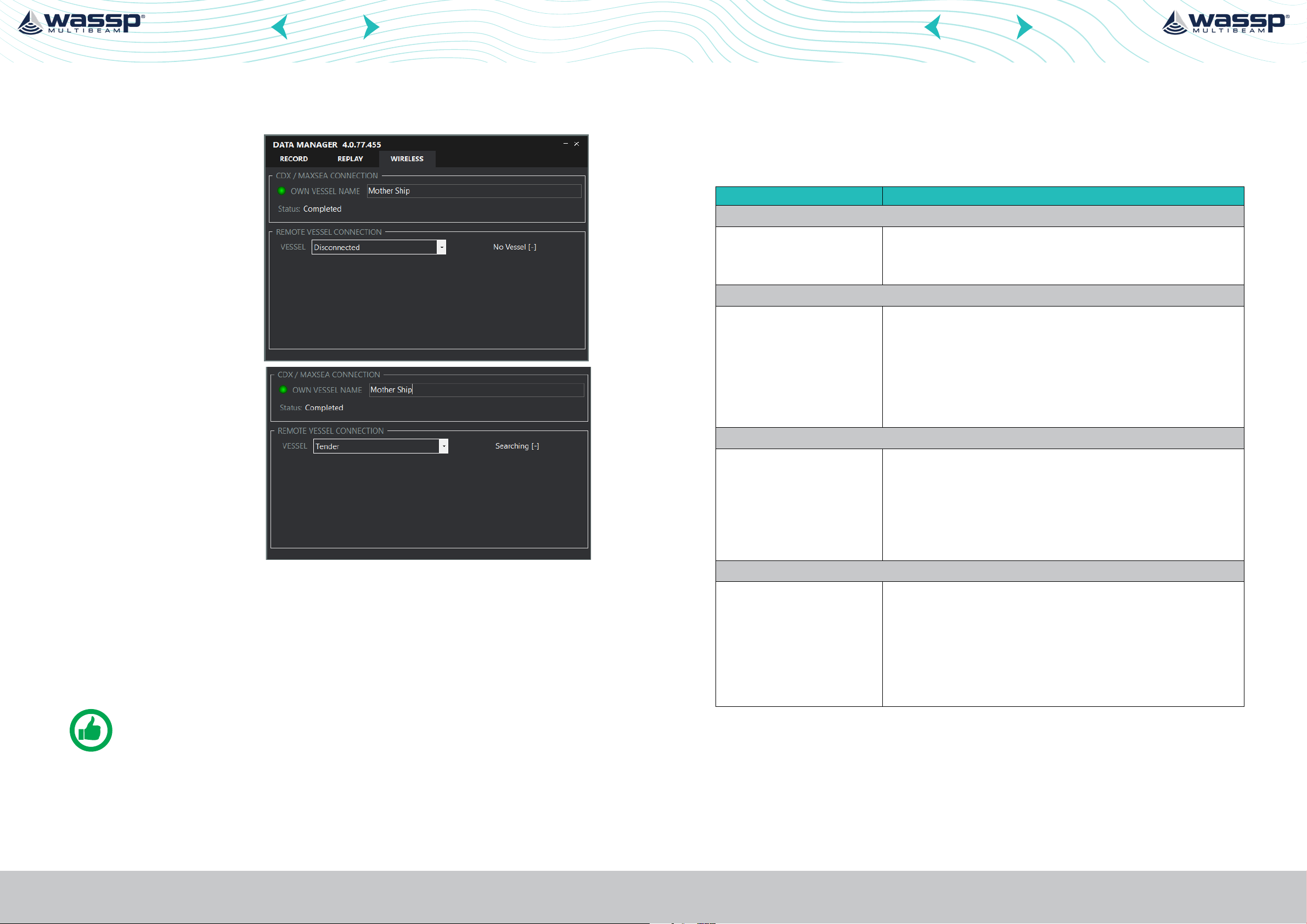
7.2. DATAMANAGER OVERVIEW
Run DATAMANAGER on the WIRELESS SERVER and it will automatically connect to the
DRX. The WIRELESS tab will be available if the Wireless license is installed.
1. Enter the nominated name
of the WIRELESS SERVER
under VESSEL NAME. This
will be used to identify
the vessel for all wireless
operations and will be the
name used to identify the
vessel by WIRELESS CLIENT
vessels. The name selected
here is ‘Tender’.
7.1.4. Sound Velocity
Sound velocity input is required to compensate for range inaccuracies caused by sound
speed variations. These changes can occur both seasonally and with geographical areas
especially in coastal areas where sound velocity will be impacted by both temperature
and water salinity dierences.
Sound velocity in water is aected by both temperature and salinity and can either be
measured directly or derived from temperature and salinity. This value should be adjusted
regularly, depending on the operating environment, as it will have a direct impact on
mapping accuracy.
The sound velocity control allows for both direct and derived values. Sound velocity
compensation can be calculated using appropriate sound velocity, sound velocity profile
or temperature and salinity sensors. The more accurate the sound velocity the more
accurate the mapping.
The visual eect of incorrect sound velocity is that a flat seafloor will either curve up or
curve down. This representation will indicate soundings that are too shallow or too deep
with the aect being accentuated toward the edges of the swath.
Sound velocity measurements can be manually reckoned using the sonar display. For
further details, refer to the CDX Operators Manual.
2. WIRELESS VESSEL is typically
not used for the WIRELESS
SERVER.
3. SCAN and connect to the
DRX using the RECORD Tab.
For further details, refer to
the CDX Operators Manual.
NOTE: WIRELESS does not require pressing the RECORD button, however the
DRX should be connected on the RECORD TAB.
7.3. INITIAL SETUP MOTHERSHIP PC
CDX software requires a GPS and Heading input to display the mothership position
relative to the Tender and the mapped chart.
Connection will typically be using a serial connection either directly or using a serial to
USB adapter connected to the CDX PC.
Once the connection between the sensor and PC is established configure the port(s)
under the WIRELESS SERVER section.
CDX supports 2 ports for own vessel data. CDX will automatically connect to the position
and heading data from the serial ports and display Own Vessel Position.
Page 26 of 40 Page 27 of 40Doc: W3 Pole Installation Manual
wassp.com wassp.com
Version: 1.0 October 2021
Doc: W3 Pole Installation Manual
Version: 1.0 October 2021
Page 15
CONTENTS CONTENTS
W3 POLE INSTALLATION MANUAL
W3 POLE INSTALLATION MANUAL
Run DATAMANAGER on the WIRELESS CLIENT. The WIRELESS tab will be available if the
Wireless license is installed.
1. Enter the nominated name of
the WIRELESS CLIENT vessel
under VESSEL NAME. This
will be used to identify the
vessel for wireless operation.
The vessel name selected
here is ‘Mother Ship’.
2. Select the name of the
WIRELESS SERVER from
the drop-down list under
WIRELESS VESSEL. In this
case ‘Tender’ is selected as
the active server.
All available WIRELESS
SERVERS on the network will
be visible and available for
selection.
8 MAINTENANCE & TROUBLESHOOTING
8.1. MAINTENANCE
Regular maintenance is important for good performance. Check the points mentioned
below every before use to keep the unit in good working order.
Checkpoint Action
Fixing bolts
» Corrosion
» If they are tightened
Top Box
» Cracks
» Foreign material
Bracket / Mount
» Replace corroded bolts.
» Tighten loosened bolts.
» Coat new bolts with marine sealant.
» If a crack is found, repair it with a small amount of
sealing compound or adhesive
» Remove foreign material with a freshwater-moistened
cloth. Do not use commercial cleaners to clean
the sensor; they can remove paint and markings or
deform the plastic.
» Replace corroded bolts.
» Tighten loosened bolts.
» Coat new bolts with marine sealant.
» Check for damage, bending or cracks, replace parts as
necessary
WIRELESS VESSEL STATUS will show as:
» NO VESSEL; No vessel available for connection.
» SEARCHING; Searching for vessel.
» SYNCING; Vessels synchronising connection.
» CONNECTED; Connection established.
» READY TO CONNECT; Connection available but not connected.
» OUT OF RANGE; Connection was established but subsequently lost.
NOTE: The number in brackets is the number of packets received from the
wireless vessel.
Page 28 of 40 Page 29 of 40Doc: W3 Pole Installation Manual
wassp.com wassp.com
Version: 1.0 October 2021
Complete Unit
» Cleaning
» Storage
Doc: W3 Pole Installation Manual
Version: 1.0 October 2021
» For long life it is recommended to wash the unit with a
low pressure hose and a mild detergent after each use.
» Store the unit is clean location in the upright position.
Dry unit before storing away
» Ensure that any cables left disconnected are covered
in a waterproof way to stop corrosion
Page 16

CONTENTS CONTENTS
W3 POLE INSTALLATION MANUAL
W3 POLE INSTALLATION MANUAL
8.2. REPLACEMENT OF FUSE
The 5A fuse (Type: FRU-2P5S-FU-5A-A, Code No.: 000-168-869-10) in the fuse holder
on the cable assembly protects the W3P sensor from overcurrent and equipment fault.
If you cannot turn on the power, check the fuse to see if it has blown. If the fuse has
blown, find the reason before you replace the fuse. If the fuse blows again after the
replacement, contact your dealer for advice.
8.3. TROUBLE SHOOTING
The table below provides simple troubleshooting procedures to restore normal
operation.
If you cannot restore normal operation, contact your dealer for advice.
Trouble Remedy
The unit will not power on » Check Power supply
» Check Fuse
» Check Connection to W3P to Power cable
I Cannot connect the DRX » Check IP address of PC
» Check W3P is powered on (LED light
sequence)
CDX software does not map » Check mapping is enabled
» Check Nav data bar to ensure all data is
received (GPS / HDG / itch /Roll / Heave) –
all are required to map
» Check Datamanager is running
Data is not received on mothership » Check datamanger is running on both tender
and mothership
» Check Datamanager on mothership is set to
receive data from the selected tender
Tender and Mothership are not
connected
» Check mothership IP address
» Ping tender bullet – open command prompt
on windows PC and type “ping 172.31.3.110”
– if data is being received check windows
firewall/antivirus is turned o
» Check POE injector
» Check Wireless connection is made via
webpage HTTPS://172.31.3.111
» Check W3P is powered on
» Check Tender PC is powered on
Page 30 of 40 Page 31 of 40Doc: W3 Pole Installation Manual
wassp.com wassp.com
Version: 1.0 October 2021
Doc: W3 Pole Installation Manual
Version: 1.0 October 2021
Page 17

CONTENTS CONTENTS
W3 POLE INSTALLATION MANUAL
W3 POLE INSTALLATION MANUAL
9 NMEA SUPPORTED SENTENCES
NMEA 0183 and serial sentences supported:
NMEA / Serial
Sentence
GGA GPS Position Fix and related data
GLL Position, Latitude/Longitude
GNS GNSS position fix data and related data
PTNL GGK Trimble Geographic Position
RMC
ZDA Time and date
HDG Magnetic Heading
HDT True Heading
Description
Navigation Information;
Position, Track Made Good and Speed Over Ground
10 SPECIFICATIONS OF W3P
TRANSCEIVER TYPE INTEGRATED DRX-32
CURRENT TRANSDUCER SUPPORT WIDEBAND FAIRING TRANSDUCER
MINIMUM DEPTH/M 1M
TYPICAL DEPTH 1/M (90° OR 2:1) 300M
MAX DEPTH 2/M (53° OR 1:1) 350M
SOUNDER DEPTH 3/M (NADIR) 400M
SWATHE COVERAGE (UP TO) 120°
DETECTION POINTS 224 (0.54° OVER 120°)
SIGNAL TYPE FM/CW
DEFAULT CENTRE FREQUENCY 160KHZ
CENTRE FREQUENCY RANGE 120-160Khz
MAXIMUM CHIRP FREQUENCY RANGE +/-30KHZ
HDM Heading Magnetic
PFEC ATT True heading (Furuno proprietary sentence), optionally pitch and roll
PFEC HVE Heave (Furuno proprietary sentence)
TSS1 Roll, pitch, heave
PASHR Roll, pitch, heave, heading
VTG Track Made Good and Ground Speed
MTW Water Temperature
FREQUENCY FROM 90-190KHZ
BANDWIDTH (UP TO) 60KHZ
RANGE RESOLUTION (MAX) 2CM
BEAM WIDTH PORT/STARBOARD 4.5° (3.6° @200KHZ)
BEAM WIDTH FORE/AFT 3.2° (2.6° @200KHZ)
SOUNDER BEAMS CONFIGURABLE 5-60°
DC INPUT 9-32V
WIRELESS ANTENNA KIT INTEGRATED
POWER CONSUMPTION (MAX) 60w
DATA CONNECTION GBE
OPERATING TEMPERATURE 0° TO 50°
ENVIRONMENTAL STANDARDS IEC60945, MIL-STD-901
MAX OPERATION SPEED 15 KNOTS
Page 32 of 40 Page 33 of 40Doc: W3 Pole Installation Manual
wassp.com wassp.com
Version: 1.0 October 2021
For Packing list see “3.1. Standard Supply” on page 9.
Doc: W3 Pole Installation Manual
Version: 1.0 October 2021
Page 18

CONTENTS CONTENTS
W3 POLE INSTALLATION MANUAL
W3 POLE INSTALLATION MANUAL
10.1. OUTLINE DRAWINGS 10.2. BASE PLATE DRAWINGS
Page 34 of 40 Page 35 of 40Doc: W3 Pole Installation Manual
wassp.com wassp.com
Version: 1.0 October 2021
Doc: W3 Pole Installation Manual
Version: 1.0 October 2021
Page 19

10.3. BRACKET DRAWINGS
CONTENTS CONTENTS
W3 POLE INSTALLATION MANUAL
W3 POLE INSTALLATION MANUAL
Page 36 of 40 Page 37 of 40Doc: W3 Pole Installation Manual
wassp.com wassp.com
Version: 1.0 October 2021
Doc: W3 Pole Installation Manual
Version: 1.0 October 2021
Page 20

CONTENTS CONTENTS
W3 POLE INSTALLATION MANUAL
W3 POLE INSTALLATION MANUAL
10.4. INTERCONNECTION DIAGRAM
11 APPENDIX: PRODUCT REGISTRATION, SUPPORT AND RESOURCES
WARRANTY
DRX products are covered with a one year limited warranty. In order to be covered by
the warranty, the WASSP DRX must be registered with WASSP Ltd. The product warranty
registration form can be filled in online by going to:
http://wassp.com/product-warranty-registration/
TECHNICAL SUPPORT
If you require maintenance and/or repair contact your local dealer. A list of WASSP dealers
and distributors is available at wassp.com.
DRX technical support is available directly through:
» Online: http://wassp.com/support/ and click on ‘Request Support’
LATEST RESOURCES
» For the latest version of manuals: http://wassp.com/support/ and click on ‘Manuals’
» For software updates and release notes: http://wassp.com/support/ and click on
‘Request Support’
» For Knowledge Base: http://support.wassp.com:8095/display/KB/
» For System drawings, mechanical drawings and declarations of conformity:
http://wassp.com/support/ and click on ‘Request Support’
Page 38 of 40 Page 39 of 40Doc: W3 Pole Installation Manual
wassp.com wassp.com
Version: 1.0 October 2021
Doc: W3 Pole Installation Manual
Version: 1.0 October 2021
Page 21

 Loading...