

Wassermann Wapo-Ex 12 II User Manual
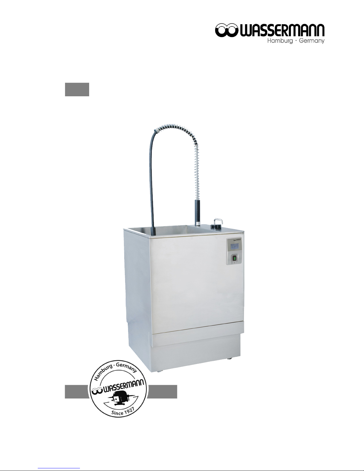
Boil Out Unit
Wapo-Ex 12 II
USER MANUAL

Dear customer,
Thank you for choosing a product from the Wassermann range. Wassermann Dental-
Maschinen incorporates the highest standards of quality and the latest technology.
In order to enjoy maximum performance and years of trouble-free operation, please read
this user manual carefully before you connect this device and start work, and operate the
device according to the recommended guidelines. The operation safety and the
functionality of this device can only be guaranteed if you follow both the general safety
guidelines and the applying laws to prevent accidents as well as the precautions given in
this user manual. We are not liable for any damages which occur due to inappropriate
usage or faulty operation of this device.
Make sure that anyone using this device has read and understood this user
manual.
Keep this user manual in a safe place where it can be referred to as required at
any time.
The unit complies with the relevant EU guidelines.
The unit is subject to the EU guidelines 2012/19/EU (WEEE Directive).
Company address:
Wassermann Dental-Maschinen GmbH
Rudorffweg 15-17
21031 Hamburg, Germany
Phone : +49 (0)40 730 926 -20/ -24 Fax.: +49 (0)40 730 37 24
export@wassermann-dental.com
www.wassermann.hamburg
www.facebook.com/WassermannDentalmaschinen
Erstellt: 31.05.18/ msc Version: 9 170970+170971 ab #158444 / Software ab V 1.53
.

Contents
1 Features....................................................................................................................................... 4
2 Safety Symbols used in this Manual.............................................................................................5
3 Safety Guidelines......................................................................................................................... 5
4 Responsibility for Operation or Damage.......................................................................................6
5 Application.................................................................................................................................... 6
6 Before Starting............................................................................................................................. 6
6.1 Transport.........................................................................................................................................6
6.2 Installation.......................................................................................................................................7
6.3 Storage............................................................................................................................................7
7 Installation/ Start-up/ Menu Functions..........................................................................................8
7.1 Water Supply...................................................................................................................................8
7.2 Fitting the Spray Gallows................................................................................................................8
7.3 Preparation......................................................................................................................................9
7.4 Start-up..........................................................................................................................................10
7.4.1 The Selector Lever....................................................................................................................... 10
8 Operation................................................................................................................................... 23
8.1 General Operating Instructions.....................................................................................................23
8.2 Operation.......................................................................................................................................24
8.3 Manual Spray Head......................................................................................................................24
9 Troubleshooting.......................................................................................................................... 25
10 Care and Maintenance............................................................................................................. 27
10.1 Cleaning......................................................................................................................................27
10.1.1 Cleaning the Wax Container (at least 1x per week, according to requirements)........................28
10.1.2 Changing the Water (at least every 6 weeks, according to requirements).................................28
10.1.3 Cleaning Procedure of the Combi Sensor v.2 (at least every 6 weeks, according to
requirements)......................................................................................................................................... 29
10.1.4 Dismount and Cleaning of the Combi Sensor v.2 (if it is very dirty, according to requirements).30
10.1.5 Lime Removal (at least 6-monthly, according to requirements)..................................................32
10.2 Maintenance................................................................................................................................32
10.3 Repairs........................................................................................................................................32
10.4 Spare Parts.................................................................................................................................32
10.5 Service Hotline 0049 (0)40 730 926 -20/ -24..............................................................................32
10.6 Scope of Delivery/ Accessories...................................................................................................33
10.7 Warranty......................................................................................................................................33
11 Technical Data......................................................................................................................... 34
12 Disposing of the Unit................................................................................................................ 34
12.1 Information on Disposal for Countries within the EU..................................................................34
13 EU Declaration of Conformity................................................................................................... 35

1 Features
The Wapo-Ex 12 II combines all-round skill, years of experience and the latest technology
to produce an outstanding product. This well-designed free standing unit with integrated
spray gallows scalds up to 12 flask halves simultaneously and fully automatically. The
innovative multifunction touch-screen terminal offers diverse functions and reproducible
procedures by simple programming. The Wapo-Ex 12 II is very durable and stands out
thanks to its flexible usage, programmable timer and automatic wax removal. The
electronic water level gauge, the leakage signal and the inlet limitation ensure additional
safety.
free standing unit for scalding up to 12 flask halves or 8 IVOCAP flask halves
multifunction touch-screen terminal for easiest operation
efficient usage thanks to its programmable timer and automatic wax removal
stainless steel construction
safety features with visual and audible signals
easy to clean and easy to operate
very durable and energy saving because of the intelligent heating control and the
high quality insulation
4
2 Safety Symbols used in this Manual
Warning!
This is a warning of risk situations and dangers.
Failure to observe this warning could be life-threatening. These warnings has to
be observed.
Information!
This symbol draws your attention to specific features that has to be observed.
3 Safety Guidelines
Configuring and operating this equipment requires precise knowledge and observance
of the instructions in this user manual. The equipment is designed only for its intended
application.
WARNING:
Servicing and repairs should be carried out only by authorized specialists.
Disconnect the power plug before starting any maintenance work.
Make sure that the equipment is connected to the correct power source.
Use heat-resistant gloves when working with the Wapo-Ex 12 II.
Risk of scalding!
Do not hold the manual spray head by the rose or hose.
Do not direct the spray at other people.
Water coming from the spray head can be at temperatures up to 95°C; only
direct the head towards the cover area or washbasin.
5
4 Responsibility for Operation or Damage
The responsibility for operating the device lies exclusively with the owner or user if said
device is incorrectly serviced, maintained or altered by persons not employed by an
authorised dealer or if the device is used in a manner contrary to its specified purpose.
The unit has to be maintained and operated in accordance with this user manual.
Wassermann Dental-Maschinen GmbH is not responsible for damage arising from the
nonobservance of these instructions.
Warranty and responsibility provisions contained in the sales and supply conditions of
Wassermann Dental-Maschinen GmbH are not extended by these instructions.
5 Application
The Wapo-Ex 12 II is suitable for scalding wax for up to 12 flask halves and also for
scalding smaller parts in the deeper cover by using the manual spray head.
Only use the device for this type of application.
6 Before Starting
6.1 Transport
Before transporting the unit, ensure that it has been unplugged from the power socket.
Make sure that it is packed correctly in order to avoid accidental damage.
Be sure to check for any transport damage when unpacking the goods. Note
down any damage if found.
6
6.2 Installation
Open the box, remove the packing materials, and carefully lift out the device and
accessories. Check the included accessories.
The device has to stand horizontally on a steady and even surface. Set the unit up close to
a water supply tap with ¾” external thread and a water drain.
Install the device in a place where it will not block the working area and the
functionality (take the dimensions into account):
Height with spray gallows: 1600 mm
Width included side wall distance (right): 700 mm
Depth included wall distance (rearwards): 670 mm
Make sure the water drain level is above 470 mm
Leave a side clearance of at least 50 mm at the right and the rear side of
the unit to allow adequate heat circulation.
Tip: Install the unit under an extractor hood to remove the steam.
It has to be fitted with a fuse (16 A / 230 V).
Do not install the unit outdoors or in places without proper ventilation.
Before start-up, be sure the device reaches room temperature.
6.3 Storage
If the unit is to be stored for an extended period, protect it from moisture and dust.
The unit location is very important when it comes to workplace safety, even if it is only to
be set up there for a short period. The room should be dry, well ventilated and vibration-
free. An even temperature and wooden supports also help.
The unit should not be stored or set up outdoors.
7
7 Installation/ Start-up/ Menu Functions
Before starting the unit, connect up the following:
7.1 Water Supply
Insert the supplied feeder hose gasket in its seat.
Connect the hose to the tap.
Connect the drain hose with the help of a hose clamp to the outlet on the unit.
Make sure the hose it at a suitable height above the feeder pipe.
The minimum amount of water should be about 4,5 l/min
at a supply pressure of 1,5- max. 6 bar.
7.2 Fitting the Spray Gallows
Raise the coil until the screw fitting can be seen.
In order to avoid injury, be sure to take hold of the spacer to raise the coil.
Angle the head over the spray area and screw in the gallows.
8

7.3 Preparation
As well as connecting the unit correctly, the following tasks need to be carried out before
you start-up:
Remove both sliding covers;
Remove the flasks, fence for small parts and scalding channel;
Swing the spray arm up and remove;
Remove the large, loose stainless steel basket;
Check that the pump filter is sitting correctly in place;
Remove remaining packaging;
Insert roller in bearing.
The roller carrier can only be inserted vertically in the vertical holder for the drive
shaft.
Reinsert the large stainless steel basket;
Fit fence for small parts in the large stainless steel basket.
Fit the spray arm on the connecting joint and swing it down (bayonet connector).
Make sure all seals are clean.
Insert the channel from the front so that any small particles can be caught in the
mesh of the large stainless steel basket.
Swing the handle in again when reinserting the flask holders.
Fit sliding cover and close (turn through 180°).
Remove cover (magnetic mount on front of unit) and close drain tap (lever
horizontal). Insert the waste container under the drain tap. Replace cover.
Open tap and check feeder hose for leaks.
The unit can be emptied using a siphon; make sure the drain hose does not leak
and is firmly attached to prevent it coming loose. If there is no waste drain, hang
the hose in a washbasin.
9
7.4 Start-up
Prior to initial operation, attach and check the feeder and drain hoses!
Firmly clamp the supplied drainage hose to the device and ensure there is a
suitable drainage facility.
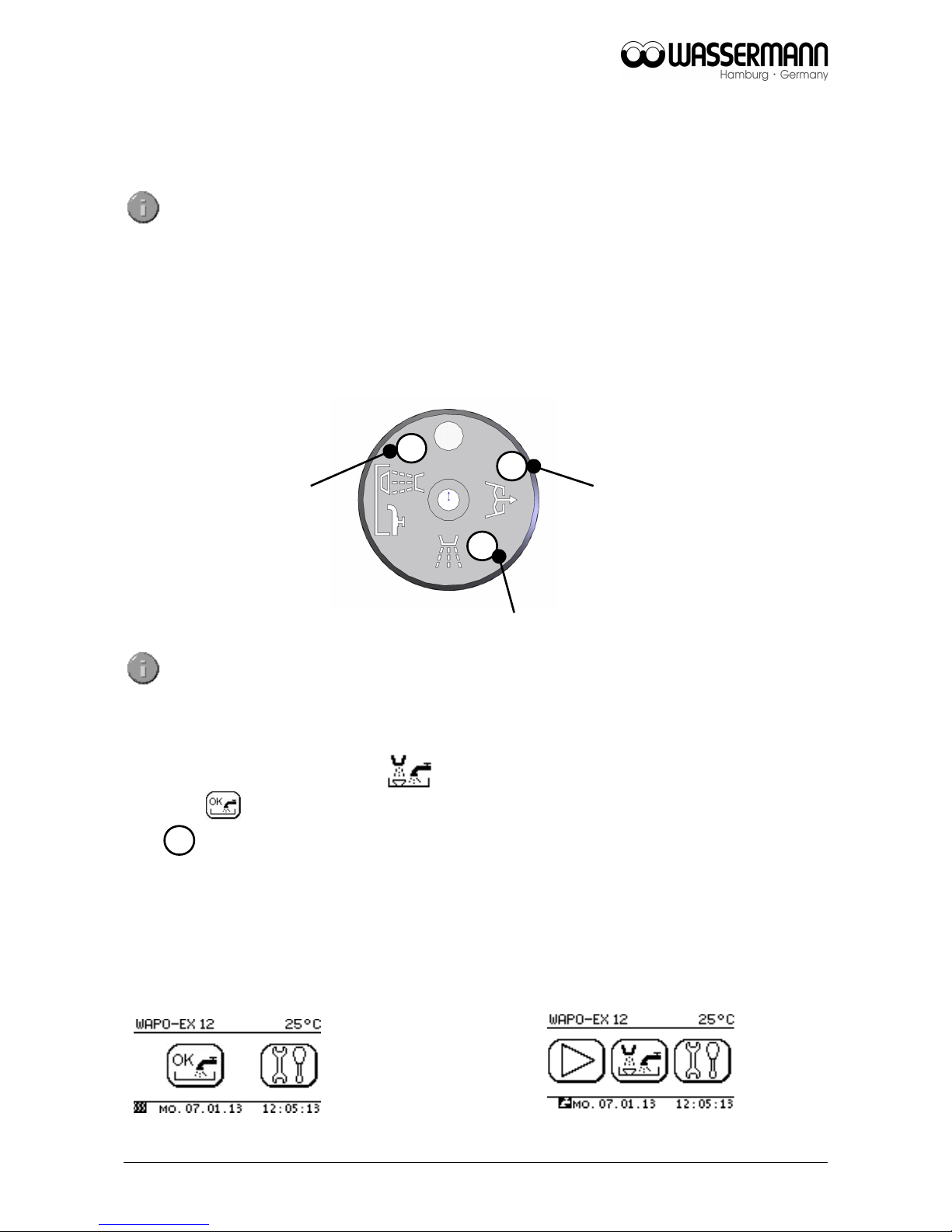
7.4.1 The Selector Lever
The following functions can be set using the selector lever:
Pull up the selector lever to unlock.
Insert the power plug into the socket, making sure that the mains and the unit operate on
the same voltage. Turn on the main switch (green rocker switch). Set the selector lever to
the "Automatic scalding" position .
Touch on and water supply is activated or if already activated before (please see
point ) the machine fills up automatically. Please note the safety function, if necessary,
pull the lever up to unlock.
After switching on the unit After switching on the unit
without automatic water supply with automatic water supply
the display shows: the display shows:
10
Automatic
scalding
Manual spraying
Pump down
6
5
19
18

Water fills the container to the working level and is heated to the operating temperature
automatically (approximately 1.5 hours). The default setting for this is 85 °C/185 °F. Add
wax remover once the operating temperature (nominal temperature display 85 °C) has
been reached. Use the manual spray to do this.
Add 100 ml wax remover (without solvent) to the scalding channel.
Set the selector lever to position. Follow unlocking procedure.
Tap the symbol on the display. The process must be ended manually. Stop the
process by pressing the symbol again.
Set the selector lever back to "Automatic scalding" again.
Wax remover only needs to be added as described above if the water is
changed or water is lost (depends on work load).
The following safety instructions have to be followed for safe work with the
manual spray:
Adjust the spray so that the spray holes are directed towards the
channels.
Do not hold the manual spray head by the rose or hose.
Do not direct the spray at other people.
We recommend the use of gloves because of the high temperatures
(up to 95°C) involved.
11
A
A
A
 Loading...