

Waspmote Plug & Sense! User Manual
Waspmote Plug & Sense!
Sensor Guide

Index
Document version: v7.7 - 03/2019
© Libelium Comunicaciones Distribuidas S.L.
INDEX
1. General ................................................................................................................................... 7
1.1. General and safety information ...................................................................................................... 7
1.2. Conditions of use .............................................................................................................................. 8
2. Introduction ..........................................................................................................................9
3. Sensors ................................................................................................................................. 10
3.1. Internal sensors .............................................................................................................................. 10
3.1.1. Accelerometer .....................................................................................................................10
3.2. Sensor probes ................................................................................................................................. 13
4. Smart Enviroment PRO ......................................................................................................14
4.2. Temperature, Humidity and Pressure Sensor Probe ................................................................. 16
4.3. Ultrasound sensor probe (MaxSonar® from MaxBotix™) ......................................................... 17
4.4. Luminosity sensor probe (Luxes accuracy) .................................................................................. 20
4.5. Carbon Monoxide (CO) Gas sensor probe for high concentrations [Calibrated] .................... 21
4.6. Carbon Monoxide (CO) Gas sensor probe for low concentrations [Calibrated] ..................... 22
4.7. Carbon Dioxide (CO2) Gas Sensor [Calibrated] ............................................................................ 23
4.8. Molecular Oxygen (O2) Gas Sensor probe [Calibrated] .............................................................. 24
4.9. Ozone (O3) Gas Sensor probe [Calibrated] .................................................................................. 25
4.10. Nitric Oxide (NO) Gas Sensor Probe for high concentrations [Calibrated] ............................ 26
4.11. Nitric Oxide (NO) Gas Sensor Probe for low concentrations [Calibrated] ............................. 27
4.12. Nitric Dioxide (NO2) Gas Sensor probe [Calibrated] ................................................................. 28
4.13. Nitric Dioxide (NO2) high accuracy Gas Sensor Probe [Calibrated] ........................................ 29
4.14. Sulfur Dioxide (SO2) Gas Sensor probe [Calibrated] ................................................................. 30
4.15. Sulfur Dioxide (SO2) high accuracy Gas Sensor Probe
[Calibrated] ............................................................................................................................................. 31
4.16. Ammonia (NH3) for low concentrations Gas Sensor
probe [Calibrated] .................................................................................................................................. 32
4.17. Ammonia (NH3) Gas Sensor Probe for high concentrations [Calibrated] .............................. 33
4.18. Methane (CH4) and Combustible Gas Sensor probe [Calibrated] ........................................... 34
4.19. Molecular Hydrogen (H2) Gas Sensor probe [Calibrated] ........................................................ 35
4.20. Hydrogen Sulde (H2S) Gas Sensor probe [Calibrated] ........................................................... 36
4.21. Hydrogen Chloride (HCl) Gas Sensor probe [Calibrated] ......................................................... 37
4.22. Hydrogen Cyanide (HCN) Gas Sensor Probe [Calibrated] ........................................................ 38
4.23. Phosphine (PH3) Gas Sensor probe [Calibrated] ....................................................................... 39
4.24. Ethylene Oxide (ETO) Gas Sensor probe [Calibrated] .............................................................. 40
4.25. Chlorine (Cl2) Gas Sensor probe [Calibrated] ............................................................................ 41
-2- v7.7

Index
4.26. Important notes for Calibrated Sensors .................................................................................... 42
4.27. Particle Matter (PM1 / PM2.5 / PM10) - Dust Sensor ................................................................ 43
4.27.1. Particle matter: the parameter ........................................................................................44
4.27.2. Measurement process ......................................................................................................44
4.27.3. Installing the Sensor Probe ..............................................................................................45
5. Smart Security ..................................................................................................................... 47
5.1. General description ........................................................................................................................ 47
5.2. Temperature, Humidity and Pressure Sensor Probe ................................................................. 49
5.3. Ultrasound sensor probe (MaxSonar® from MaxBotix™) ......................................................... 50
5.4. Luminosity sensor probe (Luxes accuracy) .................................................................................. 52
5.5. Relay Input-Output (Max: 30VDC, 1A) ........................................................................................... 53
5.5.1. Specications .......................................................................................................................53
5.5.2. Precautions for Safe Use ....................................................................................................53
5.5.3. Introduction .........................................................................................................................53
5.6. Relay Input-Output in Waspmote Plug & Sense! ......................................................................... 54
5.7. Liquid Flow sensor probes (FS100A, FS200A, FS300A, FS400, YF-S401 and YF-G1) ................ 55
5.8. Presence sensor (PIR) probe .......................................................................................................... 56
5.9. Liquid Level sensor probe .............................................................................................................. 57
5.10. Liquid Presence sensor probe (Point) ........................................................................................ 58
5.11. Liquid Presence sensor probe (Line) .......................................................................................... 58
5.12. Hall Eect sensor probe ............................................................................................................... 58
6. Smart Water ........................................................................................................................59
6.1. General description ........................................................................................................................ 59
6.2. Soil/Water Temperature (Pt-1000) sensor probe ........................................................................ 60
6.3. Conductivity sensor probe ............................................................................................................. 61
6.4. Dissolved Oxygen sensor probe ................................................................................................... 61
6.5. pH sensor probe ............................................................................................................................. 62
6.6. Oxidation-reduction potential sensor probe ............................................................................... 62
6.7. Turbidity sensor probe ................................................................................................................... 63
6.7.1. Turbidity: the parameter ....................................................................................................63
7. Smart Water Xtreme ..........................................................................................................64
7.1. General description ........................................................................................................................ 64
7.2. Optical dissolved oxygen and temperature OPTOD sensor probe .......................................... 66
7.2.1. Specications ......................................................................................................................66
7.3.1. Specications .......................................................................................................................69
7.4. Conductivity, salinity and temperature C4E sensor probe ........................................................ 70
7.4.1. Specications .......................................................................................................................71
7.5. Inductive conductivity, salinity and temperature CTZN sensor probe ..................................... 72
7.5.1. Specications .......................................................................................................................73
7.6. Turbidity and temperature NTU sensor probe ........................................................................... 74
-3- v7.7

Index
7.6.1. Specications .......................................................................................................................75
7.7. Suspended solids, turbidity, sludge blanket and temperature MES5 sensor probe .............. 76
7.7.1. Specications .......................................................................................................................77
7.8. Temperature, Humidity and Pressure Sensor Probe ................................................................. 78
7.9. Luminosity sensor probe (Luxes accuracy) .................................................................................. 79
7.10. Ultrasound sensor probe (MaxSonar® from MaxBotix™) ....................................................... 80
7.11. Eureka Manta multi sensor probe .............................................................................................. 81
7.11.1. Common specications ....................................................................................................81
7.11.2. Fluorometer Chlorophyll ..................................................................................................82
7.11.3. Fluorometer Phycocyanin (freshwater BGA) .................................................................82
7.11.4. Fluorometer Phycoerythrin (marine BGA) .....................................................................82
7.11.5. Fluorometer CDOM / FDOM ............................................................................................82
7.11.6. Ion selective electrode – Ammonium .............................................................................82
7.11.7. Ion selective electrode – Nitrate ......................................................................................82
7.11.8. Ion selective electrode – Chloride ...................................................................................83
7.11.9. Ion selective electrode – Sodium.....................................................................................83
7.11.10. Ion selective electrode – Calcium ..................................................................................83
8. Smart Water Ions ................................................................................................................ 84
8.1. General description ........................................................................................................................ 84
8.2. Soil/Water Temperature (Pt-1000) sensor probe ........................................................................ 87
8.3. Reference probes ............................................................................................................................ 88
8.4. Ion sensors ...................................................................................................................................... 89
8.5. pH sensor (for Smart Water Ions) ................................................................................................. 89
8.6. PRO Ion Sensors ............................................................................................................................. 90
9. Smart Cities PRO .................................................................................................................92
9.1. General description ........................................................................................................................ 92
9.2. Noise / Sound Level Sensor sensor probe .................................................................................. 95
9.2.1. Specifations of the Noise Level Sensor probe .................................................................95
9.2.2. Specications of the enclosure ..........................................................................................95
9.2.3. Calibration tests...................................................................................................................95
9.3. Smart environment PRO sensors .................................................................................................. 96
9.4. Important notes for Calibrated Sensors ...................................................................................... 97
10. Smart Parking ....................................................................................................................98
10.1. General description ...................................................................................................................... 98
11. Smart Agriculture .............................................................................................................99
11.1. General description ...................................................................................................................... 99
11.2. Temperature, Humidity and Pressure Sensor Probe ............................................................. 102
11.3. Ultrasound sensor probe (MaxSonar® from MaxBotix™) ..................................................... 104
11.4. Luminosity sensor probe (Luxes accuracy) ............................................................................. 106
-4- v7.7

Waspmote Plug & Sense! - Sensors Guide
11.5. Soil temperature (DS18B20) sensor probe ............................................................................. 107
11.6. Soil moisture sensor probe ....................................................................................................... 107
11.7. Weather station WS-3000 probe ............................................................................................... 109
11.8. Leaf Wetness sensor probe ....................................................................................................... 111
11.9. Soil/Water Temperature (Pt-1000) sensor probe .................................................................... 111
11.10. Solar Radiation sensor probe .................................................................................................. 112
11.11. Dendrometer sensor probe .................................................................................................... 114
12. Smart Agriculture Xtreme .............................................................................................116
12.1. General description .................................................................................................................... 116
12.2. Non-contact surface temperature measurement sensor probe (Apogee SI-411) .............. 118
12.2.1. Specications .................................................................................................................. 118
12.3. Leaf and ower bud temperature sensor probe (Apogee SF-421) ....................................... 119
12.3.1. Specications .................................................................................................................. 119
12.4. Soil oxygen level sensor probe (Apogee SO-411) ................................................................... 120
12.4.1. Specications .................................................................................................................. 121
12.5. Shortwave radiation sensor probe (Apogee SP-510) .............................................................. 122
12.5.1. Specications .................................................................................................................. 122
12.6. Solar Radiation sensor probe .................................................................................................... 123
12.7. Ultraviolet radiation sensor probe for Smart Agriculture Xtreme (Apogee SU-100) .......... 125
12.7.1. Specications .................................................................................................................. 126
12.8. Temperature, Humidity and Pressure Sensor Probe ............................................................. 127
12.9. Conductivity, water content and soil temperature GS3 sensor probe (Decagon GS3) ...... 128
12.9.1. Specications .................................................................................................................. 129
12.10. Conductivity, water content and soil temperature 5TE sensor probe (Decagon 5TE) ..... 130
12.10.1. Specications ................................................................................................................ 131
12.11. Soil temperature and volumetric water content sensor probe (Decagon 5TM) ............... 132
12.11.1. Specications ................................................................................................................ 133
12.12. Soil water potential sensor probe (Decagon MPS-6) ............................................................ 134
12.12.1. Specications ................................................................................................................ 135
12.13. Vapor pressure, temperature, barometric pressure and relative humidity sensor (Decagon
VP-4) ....................................................................................................................................................... 136
12.13.1. Specications ................................................................................................................ 137
12.14. Leaf wetness Phytos 31 sensor probe (Decagon Phytos 31) ............................................... 141
12.14.1. Specications ................................................................................................................ 141
12.15. Dendrometer sensor probes for Smart Agriculture Xtreme (Ecomatik DC2, DD-S and DF) ..
142
12.15.1. Ecomatik DC2 specications (Trunk diameter)......................................................... 142
12.15.2. Ecomatik DD-S specications (Stem diameter) ........................................................ 143
12.15.3. Ecomatik DF specications (Fruit diameter) ............................................................. 143
12.16. Weather station sensor probes (Gill Instruments MaxiMet series) .................................... 144
12.16.1. MaxiMet GMX-100 (PO) sensor probe ....................................................................... 145
12.16.2. MaxiMet GMX-300 (T-H-AP) sensor probe ................................................................ 145
12.16.3. MaxiMet GMX-200 (W) sensor probe ......................................................................... 146
12.16.4. MaxiMet GMX-240 (W-PO) sensor probe .................................................................. 147
-5- v7.7

Waspmote Plug & Sense! - Sensors Guide
12.16.5. MaxiMet GMX-300 (T-H-AP) sensor probe ................................................................ 148
12.16.6. MaxiMet GMX-301 (T-H-AP-R) sensor probe ............................................................. 148
12.16.7. MaxiMet GMX-400 (PO-T-H-AP) sensor probe .......................................................... 149
12.16.8. MaxiMet GMX-500 (W-T-H-AP) sensor probe ........................................................... 149
12.16.9. MaxiMet GMX-501 (W-T-H-AP-R) sensor probe ........................................................ 150
12.16.10. 12.17.10 MaxiMet GMX-531 (W-PT-T-H-AP-R) sensor probe ............................... 151
12.16.11. MaxiMet GMX-541 (W-PO-T-H-AP-R) sensor probe ............................................... 152
12.16.12. MaxiMet GMX-550 (W-x-T-H-AP) sensor probe ...................................................... 153
12.16.13. MaxiMet GMX-551 (W-x-T-H-AP-R) sensor probe ................................................... 154
12.16.14. MaxiMet GMX-600 (W-PO-T-H-AP) sensor probe .................................................. 155
12.16.15. Specication for each weather station sensor ....................................................... 156
12.17. Solar radiation and temperature Datasol MET probe (Atersa Datasol MET) .................... 158
12.17.1. Specications ................................................................................................................ 158
12.18. Luminosity sensor (AMS TSL2561) .......................................................................................... 159
12.18.1. Specications ................................................................................................................ 159
12.19. Ultrasound sensor probe (Maxbotix MB7040) ...................................................................... 160
12.19.1. Specications ................................................................................................................ 160
13. Ambient Control ..............................................................................................................161
13.1. General description .................................................................................................................... 161
13.2. Temperature, Humidity and Pressure Sensor Probe ............................................................. 163
13.3. Luminosity (LDR) sensor probe ................................................................................................. 164
13.4. Luminosity sensor probe (Luxes accuracy) ............................................................................. 165
13.5. Comparative between Light and Luminosity sensor .............................................................. 166
14. Radiation Control ............................................................................................................167
14.1. General description .................................................................................................................... 167
15. 4-20 mA Current Loop .....................................................................................................168
15.1. Terminal box probe .................................................................................................................... 169
15.2. DB9 probe .................................................................................................................................... 169
16. Documentation changelog ............................................................................................170
17. Certications ................................................................................................................... 171
-6- v7.7

Waspmote Plug & Sense! - Sensors Guide
1. General
Important:
All documents and any examples they contain are provided as-is and are subject to change without notice. Except
to the extent prohibited by law, Libelium makes no express or implied representation or warranty of any kind with
regard to the documents, and specically disclaims the implied warranties and conditions of merchantability and
tness for a particular purpose.
The information on Libelium’s websites has been included in good faith for general informational purposes only.
It should not be relied upon for any specic purpose and no representation or warranty is given as to its accuracy
or completeness.
1.1. General and safety information
• In this section, the term “Waspmote” encompasses both the Waspmote device itself and its modules and
sensor boards.
• Read through the document “General Conditions of Libelium Sale and Use”.
• Do not allow contact of metallic objects with the electronic part to avoid injuries and burns.
• NEVER submerge the device in any liquid.
• Keep the device in a dry place and away from any liquid which may spill.
• Waspmote consists of highly sensitive electronics which is accessible to the exterior, handle with great care
and avoid bangs or hard brushing against surfaces.
• Check the product specications section for the maximum allowed power voltage and amperage range and
consequently always use a current transformer and a battery which works within that range. Libelium is only
responsible for the correct operation of the device with the batteries, power supplies and chargers which it
supplies.
• Keep the device within the specied range of temperatures in the specications section.
• Do not connect or power the device with damaged cables or batteries.
• Place the device in a place only accessible to maintenance personnel (a restricted area).
• Keep children away from the device in all circumstances.
• If there is an electrical failure, disconnect the main switch immediately and disconnect that battery or any
other power supply that is being used.
• If using a car lighter as a power supply, be sure to respect the voltage and current data specied in the “Power
Supplies” section.
• If using a battery in combination or not with a solar panel as a power supply, be sure to use the voltage and
current data specied in the “Power supplies” section.
• If a software or hardware failure occurs, consult the Libelium Web Development section
• Check that the frequency and power of the communication radio modules together with the integrated
antennas are allowed in the area where you want to use the device.
• Waspmote is a device to be integrated in a casing so that it is protected from environmental conditions such
as light, dust, humidity or sudden changes in temperature. The board supplied “as is” is not recommended for
a nal installation as the electronic components are open to the air and may be damaged.
-7- v7.7

Waspmote Plug & Sense! - Sensors Guide
1.2. Conditions of use
• Read the “General and Safety Information” section carefully and keep the manual for future consultation.
• Use Waspmote in accordance with the electrical specications and the environment described in the “Electrical
Data” section of this manual.
• Waspmote and its components and modules are supplied as electronic boards to be integrated within a nal
product. This product must contain an enclosure to protect it from dust, humidity and other environmental
interactions. In the event of outside use, this enclosure must be rated at least IP-65.
• Do not place Waspmote in contact with metallic surfaces; they could cause short-circuits which will permanently
damage it.
Further information you may need can be found at: http://www.libelium.com/development/plug-sense
The “General Conditions of Libelium Sale and Use” document can be found at:
http://www.libelium.com/development/plug-sense/technical_service/
-8- v7.7
Waspmote Plug & Sense! - Sensors Guide
2. Introduction
In this document, all the possible congurations of the Plug & Sense! line are described, including a general
description of all the possible applications and the technical specications of the sensors associated to each one
of them.
For a deep description of the characteristics of the Plug & Sense! line, please refer to the Waspmote Plug & Sense!
Technical Guide. You can nd it, along with other useful information such as the Waspmote and Sensor boards
technical and programming guides, in the Development section of the Libelium website at http://www.libelium.com/
development/plug-sense
For detailed info about sensors or probes we do NOT recommend this Guide, but the dedicated guide for the
sensor board. Example: if you have a Plug & Sense! Smart Cities PRO, we advise reading the Smart Cities PRO
Technical Guide.
Note that no code for reading the sensors has been included in this guide. For programming the Waspmote Plug
& Sense! notes, please use the default examples provided for each sensor, available at: http://www.libelium.com/
development/plug-sense/examples/
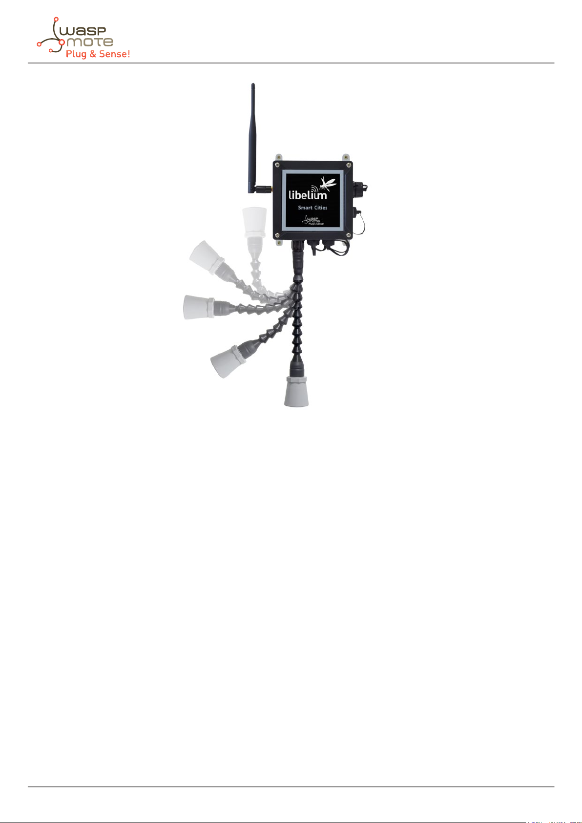
Figure: Waspmote Plug & Sense! line
-9- v7.7
3. Sensors
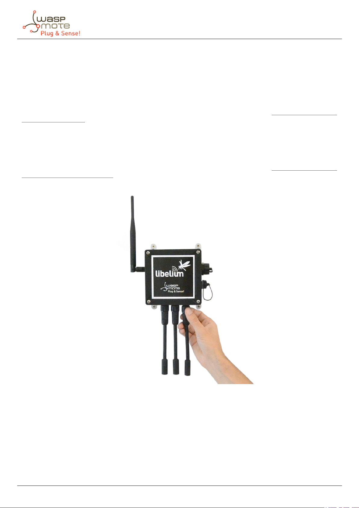
Figure: Image of Waspmote Plug & Sense!
3.1. Internal sensors
Waspmote Plug & Sense! - Sensors Guide
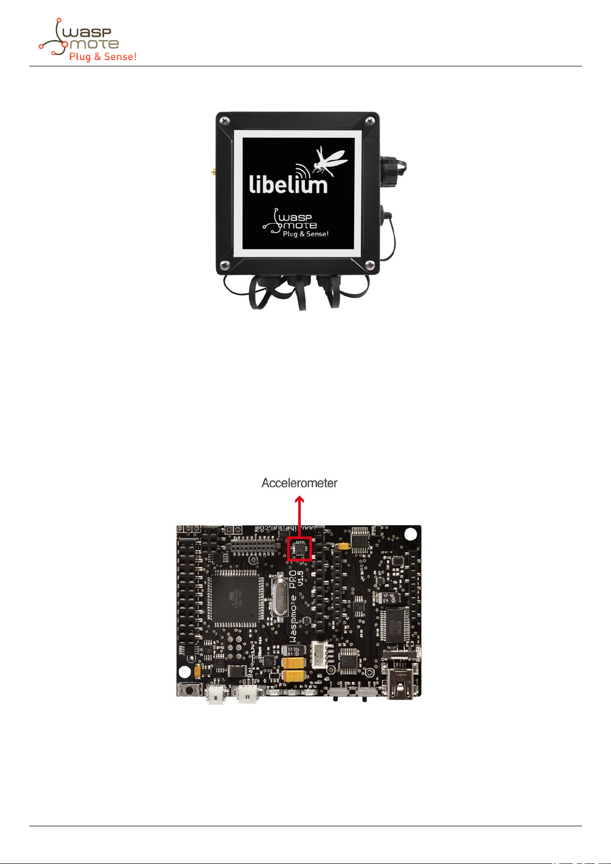
3.1.1. Accelerometer
Waspmote has a built-in acceleration sensor LIS3331LDH, by STMicroelectronics, which informs the mote of
acceleration variations experienced on each one of the 3 axes (X,Y, Z).
The integration of this sensor allows the measurement of acceleration on the 3 axes (X, Y, Z), establishing 4 kinds
of events: Free Fall, inertial wake up, 6D movement and 6D position which are explained in the Interruption
Programming Guide.
Figure: Accelerometer
The LIS331DLH has dynamically user-selectable full scales of ±2g/±4g/±8g and it is capable of measuring
accelerations with output data rates from 0.5 Hz to 1 kHz.
The device features ultra low-power operational modes that allow advanced power saving and smart sleep to
wake-up functions.
-10- v7.7
Waspmote Plug & Sense! - Sensors Guide
The accelerometer has several power modes, the output data rate (ODR) will depend on the power mode selected.
The power modes and output data rates are shown in this table:
Power mode Output data rate (Hz)
Power down --
Normal mode 1000
Low-power 1 0.5
Low-power 2 1
Low-power 3 2
Low-power 4 5
Low-power 5 10
This accelerometer has an auto-test capability that allows the user to check the functioning of the sensor in the
nal application. Its operational temperature range is between -40 ºC and +85 ºC.
The accelerometer communicates with the microcontroller through the I2C interface. The pins that are used for
this task are the SCL pin and the SDA pin, as well as another interruption pin to generate the interruptions.
The accelerometer has 4 types of event which can generate an interrupt: free fall, inertial wake up, 6D movement
and 6D position.
These thresholds and times are set in the WaspACC.h le.
To show the ease of programming, an extract of code about how to get the accelerometer values is included
below:
{
ACC.ON();
ACC.getX();
ACC.getY();
ACC.getZ();
}
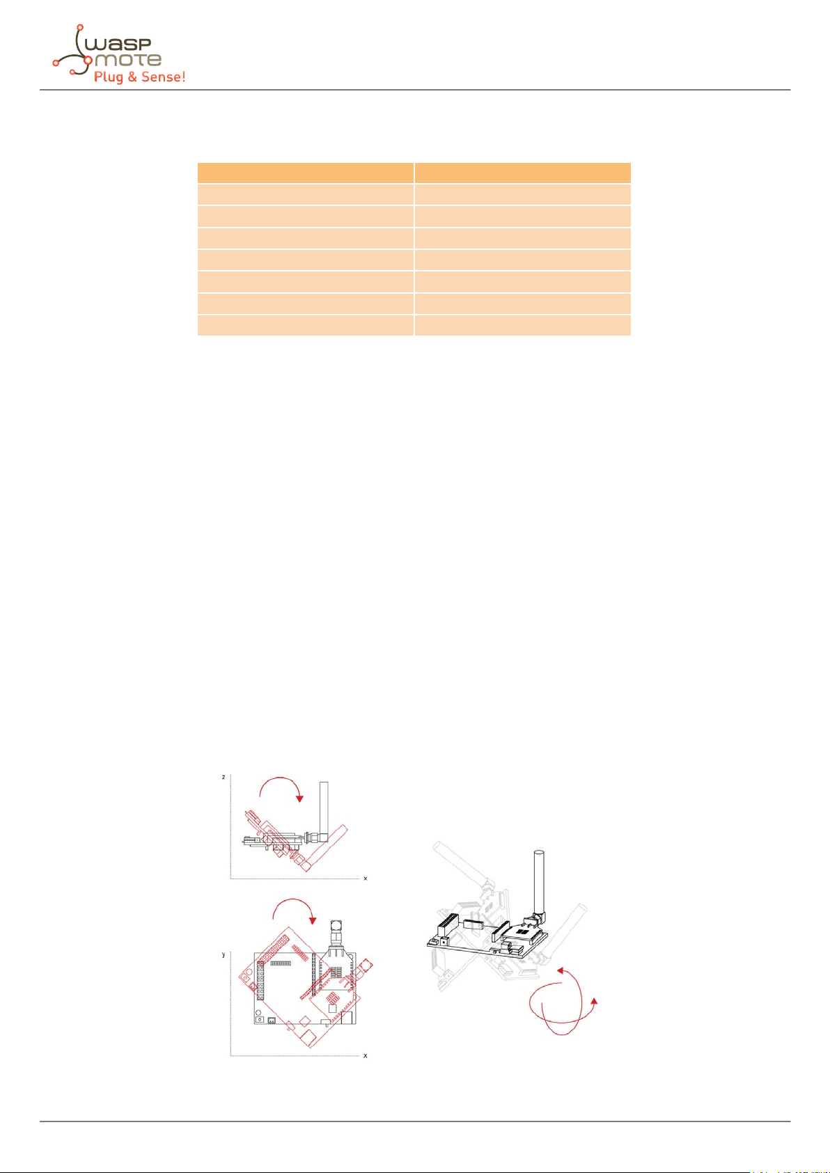
Some gures with possible uses of the accelerometer are shown below:
Rotation and twist:
-11- v7.7
Free fall of objects in which it is installed:
Waspmote Plug & Sense! - Sensors Guide
Crash:
More information about interruptions generated by the accelerometer can be found in the chapter “Interruptions”
and in the Interruption Programming Guide.
Related API libraries: WaspACC.h, WaspACC.cpp
All information about their programming and operation can be found in the Accelerometer Programming Guide.
All the documentation is located in the Development section in the Libelium website.
-12- v7.7

Waspmote Plug & Sense! - Sensors Guide
3.2. Sensor probes
All sensing capabilities of Waspmote Plug & Sense! are provided by sensor probes. Each sensor probe contains one
sensor, some necessary protections against outdoor environmental conditions and a waterproof male connector.
The standard length of a sensor probe is about 150 mm, including waterproof connector, but it could vary due to
some sensors need special dimensions. Weight of a standard probe rounds 20 g, but there are some special cases
where this weight can rise.
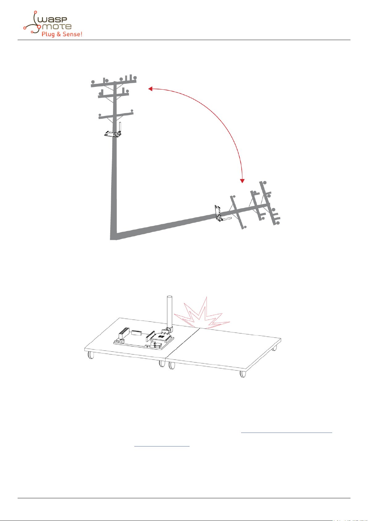
Sensor probes are designed to be used in vertical position (with the sensor looking to the ground). In this position,
the protection cap of each sensor probe is eective against rain.
-13- v7.7
Waspmote Plug & Sense! - Sensors Guide
4. Smart Enviroment PRO
4.1. Smart Environment PRO
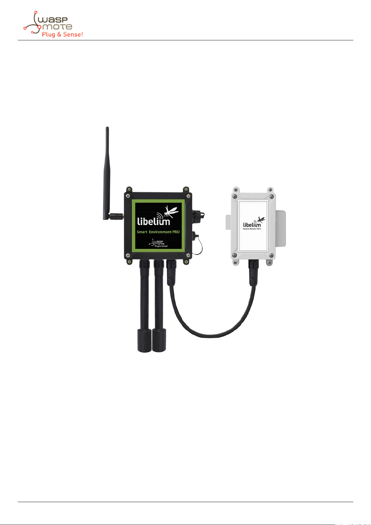
The Smart Environment PRO model has been created as an evolution of Smart Environment. It enables the user
to implement pollution, air quality, industrial, environmental or farming projects with high requirements in terms
of high accuracy, reliability and measurement range as the sensors come calibrated from factory.
Figure: Smart Environment PRO Waspmote Plug & Sense! model
-14- v7.7

Sensor sockets are congured as shown in the gure below.
Waspmote Plug & Sense! - Sensors Guide
Sensor
Socket
Sensor probes allowed for each sensor socket
Parameter Reference
Carbon Monoxide (CO) for low concentrations [Calibrated] 9371-LC-P
Carbon Dioxide (CO2) [Calibrated] 9372-P
Oxygen (O2) [Calibrated] 9373-P
Ozone (O3) [Calibrated] 9374-P
Nitric Oxide (NO) for low concentrations [Calibrated] 9375-LC-P
Nitric Dioxide (NO2) high accuracy [Calibrated] 9376-HA-P
Sulfur Dioxide (SO2) high accuracy [Calibrated] 9377-HA-P
Ammonia (NH3) for low concentrations [Calibrated] 9378-LC-P
Ammonia (NH3) for high concentrations [Calibrated] 9378-HC-P
Methane (CH4) and Combustible Gas [Calibrated] 9379-P
Hydrogen (H2) [Calibrated] 9380-P
Hydrogen Sulde (H2S) [Calibrated] 9381-P
Hydrogen Chloride (HCl) [Calibrated] 9382-P
Hydrogen Cyanide (HCN) [Calibrated] 9383-P
Phosphine (PH3) [Calibrated] 9384-P
Ethylene (ETO) [Calibrated] 9385-P
Chlorine (Cl2) [Calibrated] 9386-P
D Particle Matter (PM1 / PM2.5 / PM10) - Dust 9387-P
Temperature, humidity and pressure 9370-P
E
Luminosity (Luxes accuracy) 9325-P
Ultrasound (distance measurement) 9246-P
Figure: Sensor sockets configuration for Smart Environment PRO model
Note: For more technical information about each sensor probe go to the Development section on the Libelium website.
Calibrated gas sensors are manufactured once the order has been placed to ensure maximum durability of the
calibration feature. The manufacturing process and delivery may take from 4 to 6 weeks. The lifetime of calibrated
gas sensors is 6 months working at maximum accuracy. We strongly encourage our customers to buy extra gas
sensors to replace the original ones after that time to ensure maximum accuracy and performance.
-15- v7.7
Waspmote Plug & Sense! - Sensors Guide
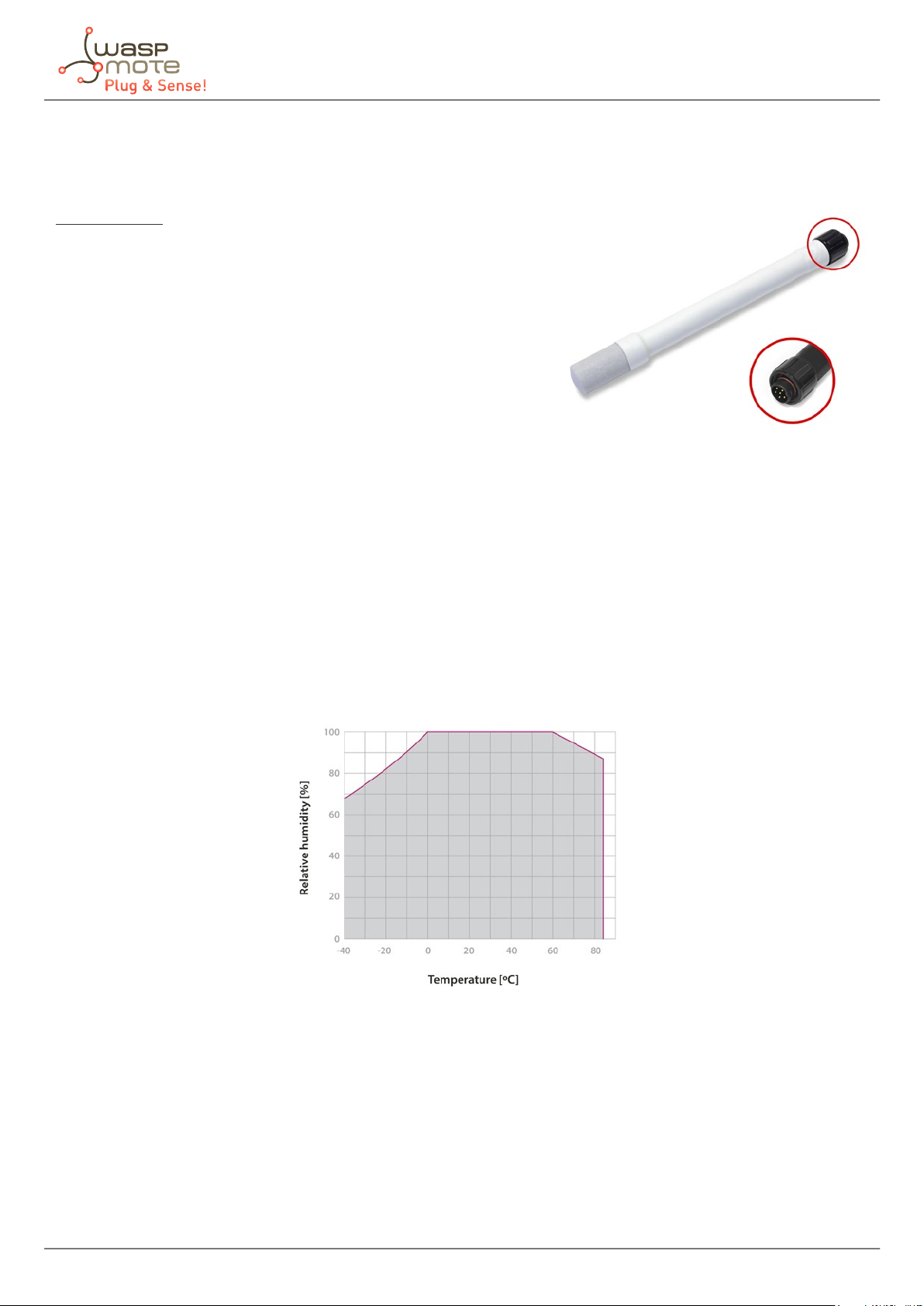
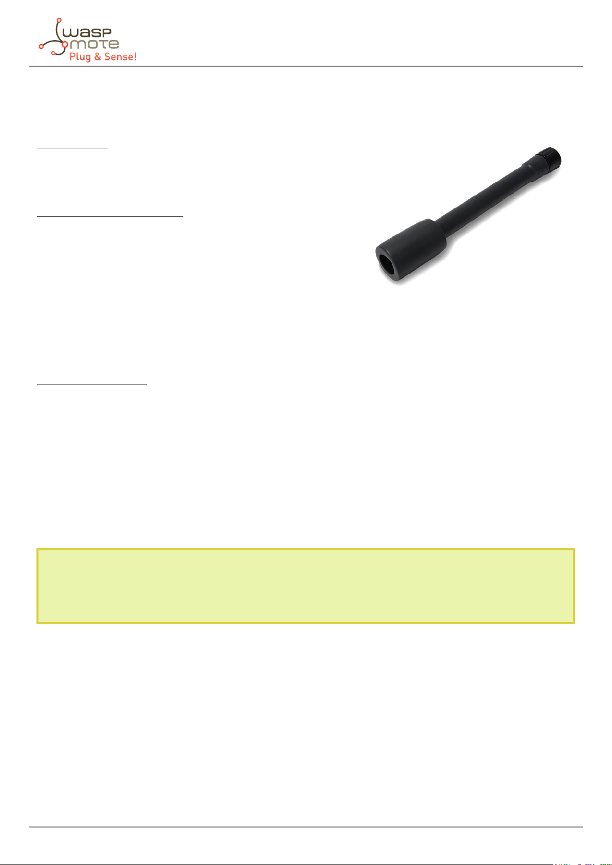
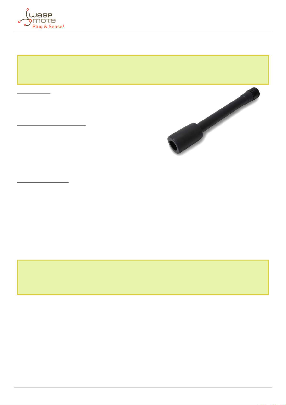
4.2. Temperature, Humidity and Pressure Sensor Probe
The BME280 is a digital temperature, humidity and atmospheric pressure sensor developed by Bosch Sensortec.
Specications
Electrical characteristics
Supply voltage: 3.3 V
Sleep current typical: 0.1 μA
Sleep current maximum: 0.3 μA
Temperature sensor
Operational range: -40 ~ +85 ºC
Full accuracy range: 0 ~ +65 ºC
Accuracy: ±1 ºC (range 0 ºC ~ +65 ºC)
Response time: 1.65 seconds (63% response from +30 to +125 °C).
Typical consumption: 1 μA measuring
Humidity sensor
Measurement range: 0 ~ 100% of relative humidity (for temperatures < 0 °C and > 60 °C see gure below)
Accuracy: < ±3% RH (at 25 ºC, range 20 ~ 80%)
Hysteresis: ±1% RH
Operating temperature: -40 ~ +85 ºC
Response time (63% of step 90% to 0% or 0% to 90%): 1 second
Typical consumption: 1.8 μA measuring
Maximum consumption: 2.8 μA measuring
Figure: Image of the Temperature, Hu-
midity and Pressure Sensor Probe
Figure: Humidity sensor operating range
Pressure sensor
Measurement range: 30 ~ 110 kPa
Operational temperature range: -40 ~ +85 ºC
Full accuracy temperature range: 0 ~ +65 ºC
Absolute accuracy: ±0.1 kPa (0 ~ 65 ºC)
Typical consumption: 2.8 μA measuring
Maximum consumption: 4.2 μA measuring
-16- v7.7
Waspmote Plug & Sense! - Sensors Guide
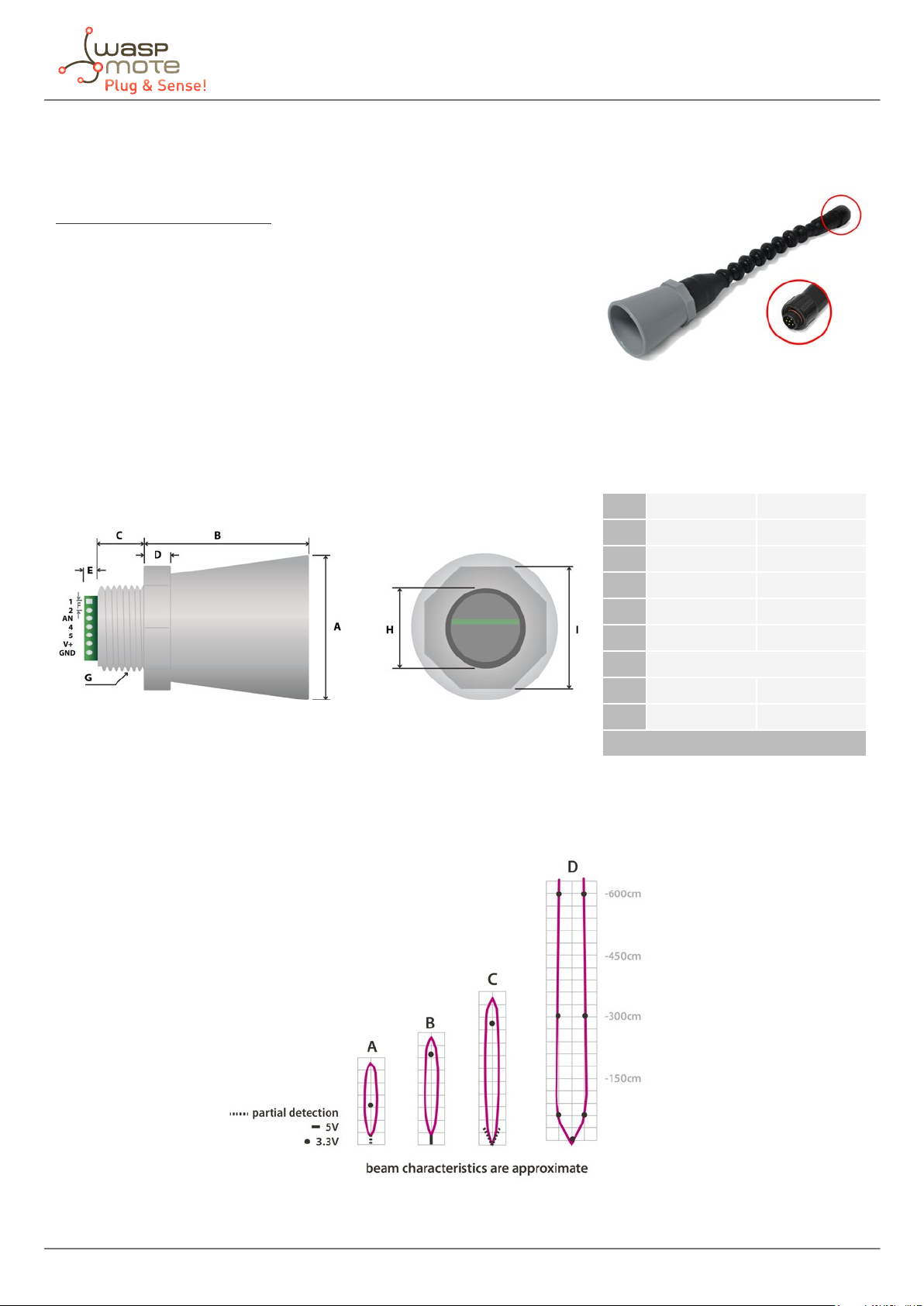
4.3. Ultrasound sensor probe (MaxSonar® from MaxBotix™)
I2CXL-MaxSonar®-MB7040™
Operation frequency: 42 kHz
Maximum detection distance: 765 cm
Interface: Digital bus
Power supply: 3.3 V ~ 5 V
Consumption (average): 2.1 mA (powered at 3.3 V) – 3.2 mA (powered at 5
V)
Consumption (peak): 50 mA (powered at 3.3 V) – 100 mA (powered at 5 V)
Usage: Indoors and outdoors (IP-67)
Figure: Ultrasonic I2CXL-MaxSonar®-MB7040 from MaxBotix™
sensor
A 1.72” dia. 43.8 mm dia.
B 2.00” 50.7 mm
C 0.58” 14.4 mm
D 0.31” 7.9 mm
E 0.18” 4.6 mm
F 0.1” 2.54 mm
G 3/4” National Pipe Thread Straight
H 1.032” dia. 26.2 dia.
I 1.37” 34.8 mm
weight: 1.76 oz. ; 50 grams
Figure: Ultrasonic I2CXL-MaxSonar®-MB7040 sensor dimensions
In the gure below we can see a diagram of the detection range of the sensor developed using dierent detection
patterns (a 0.63 cm diameter dowel for diagram A, a 2.54 cm diameter dowel for diagram B, an 8.25 cm diameter
rod for diagram C and a 28 cm wide board for diagram D):
-17- v7.7

Waspmote Plug & Sense! - Sensors Guide
Figure: Diagram of the sensor beam extracted from the data sheet of the XL-MaxSonar®-WRA1™ sensor from MaxBotix
-18- v7.7
Waspmote Plug & Sense! - Sensors Guide
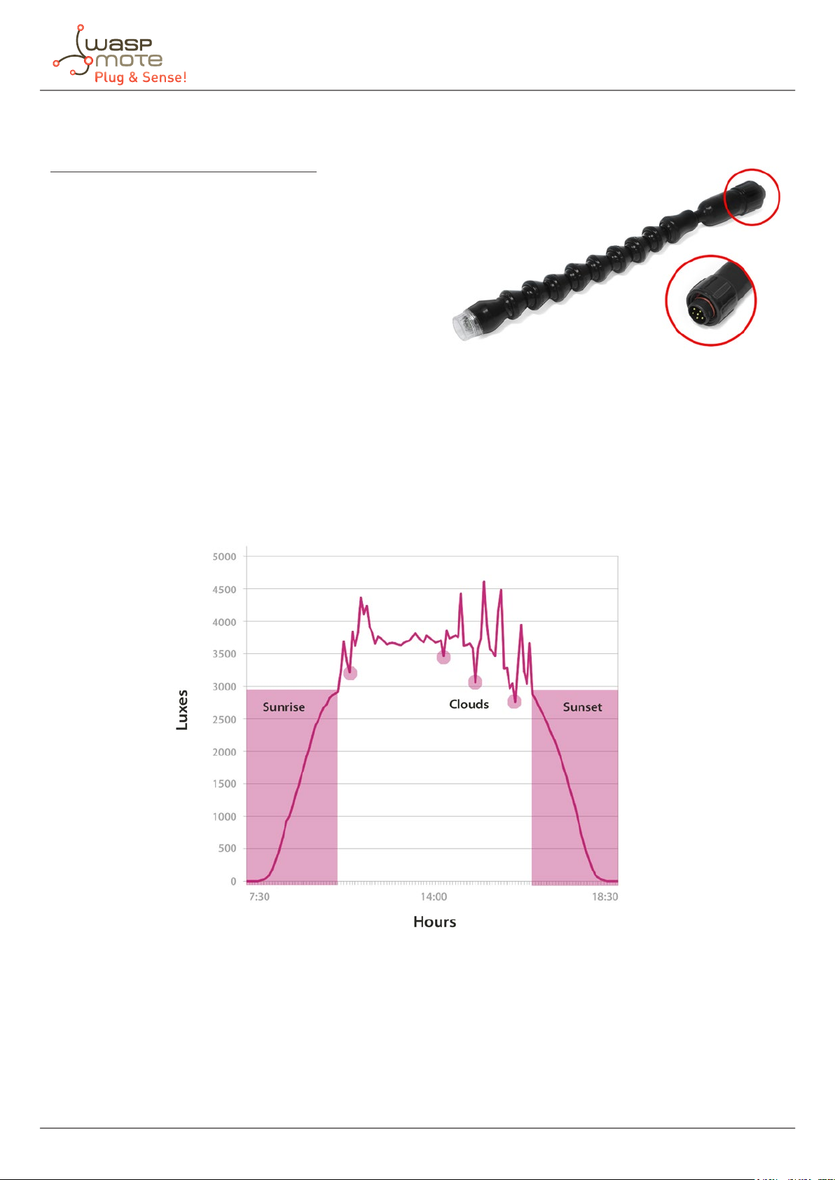
Figure: Image of congurations of the ultrasound sensor probe
As we see in the gure, the ultrasound sensor probe may be placed in dierent positions. The sensor can be
focused directly to the point we want to measure.
-19- v7.7
Waspmote Plug & Sense! - Sensors Guide
4.4. Luminosity sensor probe (Luxes accuracy)
Sensor specications (Luxes accuracy)
Dynamic range: 0.1 to 40000 Lux
Spectral range: 300 – 1100 nm
Voltage range: 2.7 – 3.6 V
Operating temperature: -30 ºC to +80 ºC
Typical consumption: 0.24 mA
Maximum consumption: 0.6 mA
Usage: Indoors and outdoors
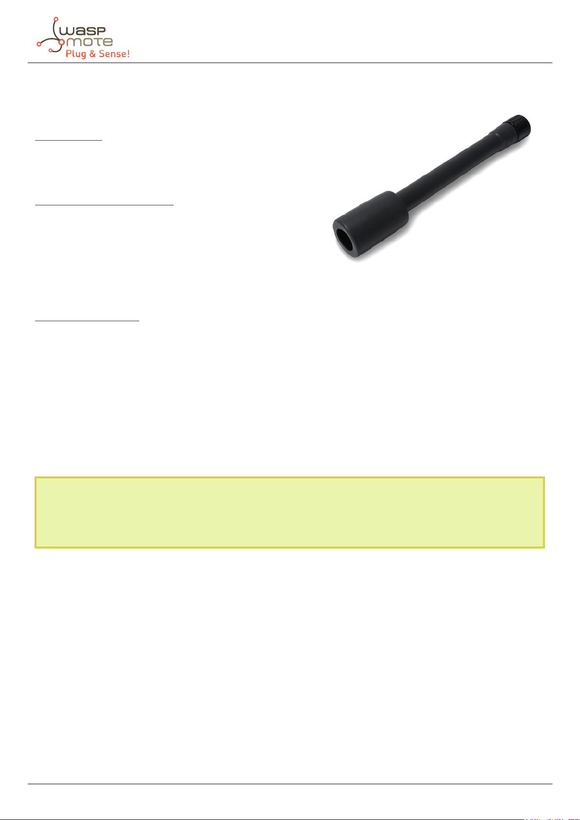
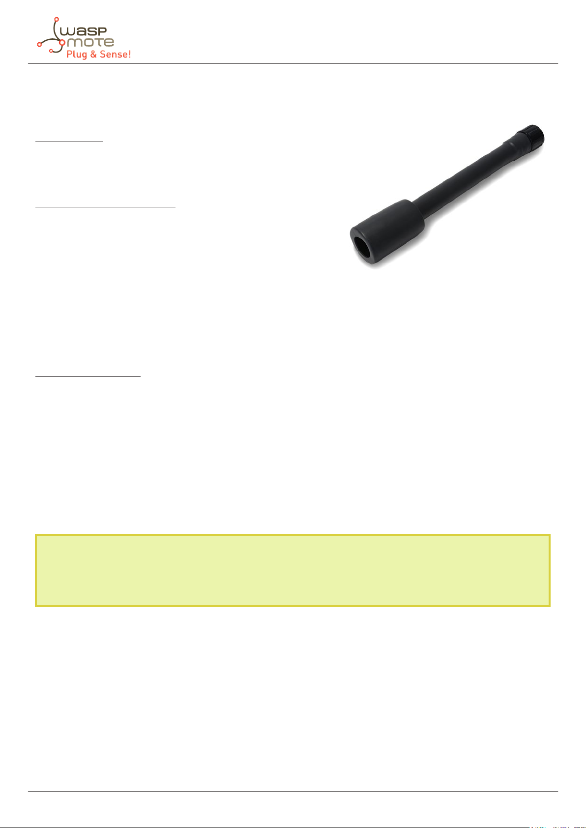
Figure: Image of the Luminosity sensor probe (Luxes accuracy)
This is a light-to-digital converter that transforms light intensity into a digital signal output. This device combines
one broadband photo-diode (visible plus infrared) and one infrared-responding photo-diode on a single CMOS
integrated circuit capable of providing a near-photopic response over an eective 20-bit dynamic range (16-bit
resolution). Two integrating ADCs convert the photo-diode currents to a digital output that represents the irradiance
measured on each channel. This digital output in lux is derived using an empirical formula to approximate the
human eye response.
Figure: Image of the Luminosity sensor probe (Luxes accuracy)
-20- v7.7
Waspmote Plug & Sense! - Sensors Guide
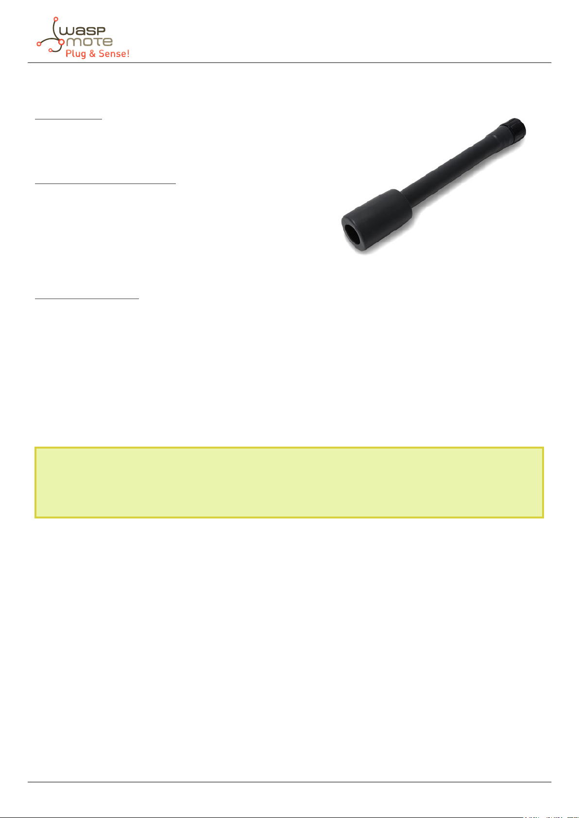
4.5. Carbon Monoxide (CO) Gas sensor probe for high concentrations [Calibrated]
Specications
Gas: CO
Sensor: 4-CO-500
Performance Characteristics
Nominal Range: 0 to 500 ppm
Maximum Overload: 2000 ppm
Long Term Output Drift: < 2% signal/month
Response Time (T90): ≤ 30 seconds
Sensitivity: 70 ± 15 nA/ppm
Accuracy: as good as ±1 ppm* (ideal conditions)
Operation Conditions
Temperature Range: -20 ºC to 50 ºC
Operating Humidity: 15 to 90% RH non-condensing
Pressure Range: 90 to 110 kPa
Storage Temperature: 0 ºC to 20 ºC
Expected Operating Life: 5 years in air
Figure: Image of the Carbon Monoxide Sensor Probe
for high concentrations
Average consumption: less than 1 mA
* Accuracy values are only given for the optimum case. Read the Gases PRO Technical Guide for more details.
Calibrated gas sensors are manufactured once the order has been placed to ensure maximum durability of the
calibration feature. The manufacturing process and delivery may take from 4 to 6 weeks. The lifetime of calibrated
gas sensors is 6 months working at maximum accuracy. We strongly encourage our customers to buy extra gas
sensors to replace the original ones after that time to ensure maximum accuracy and performance.
-21- v7.7
Waspmote Plug & Sense! - Sensors Guide
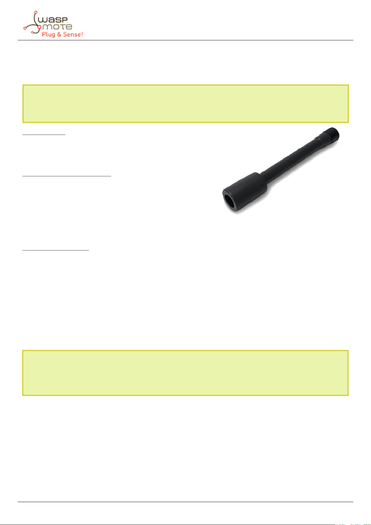
4.6. Carbon Monoxide (CO) Gas sensor probe for low concentrations [Calibrated]
Specications
Gas: CO
Sensor: CO-A4
Performance Characteristics
Nominal Range: 0 to 25 ppm
Maximum Overload: 2000 ppm
Long Term Sensitivity Drift: < 10% change/year in lab air, monthly
test
Long Term zero Drift: < ±100 ppb equivalent change/year in lab
air
Response Time (T90): ≤ 20 seconds
Sensitivity: 220 to 375 nA/ppm
Accuracy: as good as ±0.1 ppm* (ideal conditions)
H2S lter capacity: 250000 ppm·hrs
Figure: Image of the Carbon Monoxide Sensor Probe
for low concentrations
Operation Conditions
Temperature Range: -30 ºC to 50 ºC
Operating Humidity: 15 to 90% RH non-condensing
Pressure Range: 80 to 120 kPa
Storage Temperature: 0 ºC to 20 ºC
Expected Operating Life: 3 years in air
Average consumption: less than 1 mA
* Accuracy values are only given for the optimum case. Read the Gases PRO Technical Guide for more details.
Calibrated gas sensors are manufactured once the order has been placed to ensure maximum durability of the
calibration feature. The manufacturing process and delivery may take from 4 to 6 weeks. The lifetime of calibrated
gas sensors is 6 months working at maximum accuracy. We strongly encourage our customers to buy extra gas
sensors to replace the original ones after that time to ensure maximum accuracy and performance.
-22- v7.7

Waspmote Plug & Sense! - Sensors Guide
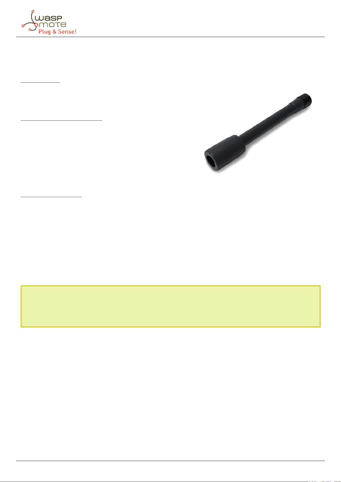
4.7. Carbon Dioxide (CO2) Gas Sensor [Calibrated]
Specications
Gas: CO
Sensor: INE20-CO2P-NCVSP
Performance Characteristics
Nominal Range: 0 to 5000 ppm
Long Term Output Drift: < ±250 ppm/year
Warm up time: 60 seconds @ 25 ºC
At least 30 min for full specication @ 25 °C
Response Time (T90): ≤ 60 seconds
Resolution: 25 ppm
Accuracy: as good as ±50 ppm*, from 0 to 2500 ppm range (ideal conditions)
as good as ±200 ppm*, from 2500 to 5000 ppm range (ideal conditions)
Operation Conditions
Temperature Range: -40 ºC to 60 ºC
Operating Humidity: 0 to 95% RH non-condensing
Storage Temperature: -40 ºC to 85 ºC
MTBF: ≥ 5 years
Average consumption: 80 mA
2
Figure: Image of the Carbon Dioxide Sensor Probe
Note: The CO2 Sensor and the Methane (CH4) and Combustible Gas Sensor have high power requirements and
cannot work together in the same Gases PRO Sensor Board. The user must choose one or the other, but not both.
* Accuracy values are only given for the optimum case. Read the Gases PRO Technical Guide for more details.
Calibrated gas sensors are manufactured once the order has been placed to ensure maximum durability of the
calibration feature. The manufacturing process and delivery may take from 4 to 6 weeks. The lifetime of calibrated
gas sensors is 6 months working at maximum accuracy. We strongly encourage our customers to buy extra gas
sensors to replace the original ones after that time to ensure maximum accuracy and performance.
-23- v7.7
Waspmote Plug & Sense! - Sensors Guide
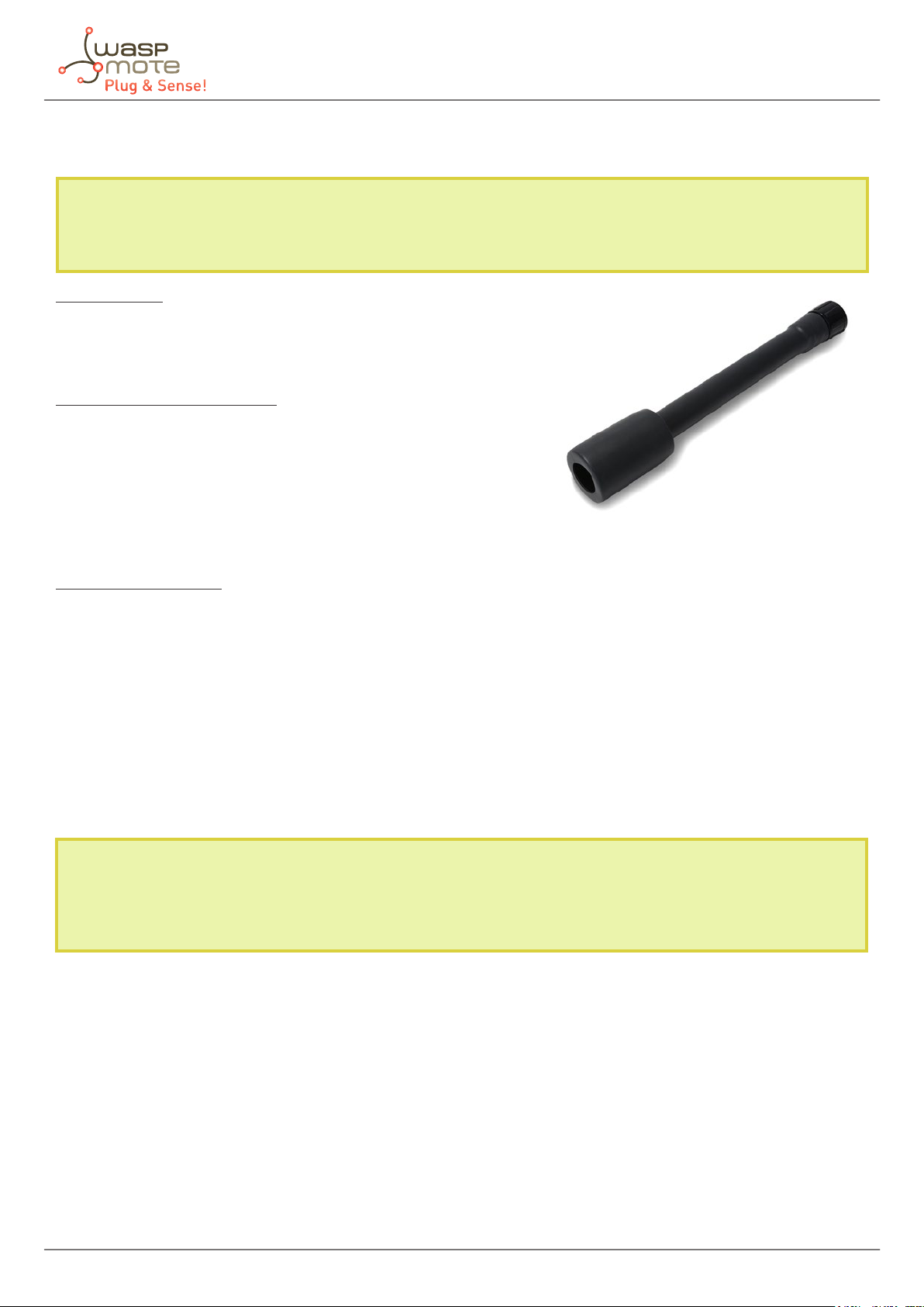
4.8. Molecular Oxygen (O2) Gas Sensor probe [Calibrated]
Specications
Gas: O
Sensor: 4-OL
Performance Characteristics
Nominal Range: 0 to 30 Vol.%
Maximum Overload: 90 Vol.%
Long Term Output Drift: < 2% signal/3 months
Response Time (T90): ≤ 30 seconds
Sensitivity: 1.66 ± 0.238 nA/ppm
Accuracy: as good as ± 0.1 % (ideal conditions)
Operation Conditions
Temperature Range: -20 ºC to 50 ºC
Operating Humidity: 5 to 90 % RH non-condensing
Pressure Range: 90 to 110 kPa
Storage Temperature: 0 ºC to 20 ºC
Expected Operating Life: 2 years in air
Average consumption: less than 1 mA
2
Figure: Image of the Molecular Oxygen Sensor Probe
* Accuracy values are only given for the optimum case. Read the Gases PRO Technical Guide for more details.
Calibrated gas sensors are manufactured once the order has been placed to ensure maximum durability of the
calibration feature. The manufacturing process and delivery may take from 4 to 6 weeks. The lifetime of calibrated
gas sensors is 6 months working at maximum accuracy. We strongly encourage our customers to buy extra gas
sensors to replace the original ones after that time to ensure maximum accuracy and performance.
-24- v7.7

Waspmote Plug & Sense! - Sensors Guide
4.9. Ozone (O3) Gas Sensor probe [Calibrated]
Specications
Gas: O
Sensor: OX-A431
Performance Characteristics
Nominal Range: 0 to 18 ppm
Maximum Overload: 50 ppm
Long Term sensitivity Drift: -20 to -40% change/year
Response Time (T90): ≤ 45 seconds
Sensitivity: -200 to -550 nA/ppm
Accuracy: as good as ±0.2 ppm* (ideal conditions)
High cross-sensitivity with NO2 gas. Correction could be necessary in ambients with NO2.
Operation Conditions
Temperature Range: -20 ºC to 40 ºC
Operating Humidity: 15 to 85% RH non-condensing
Pressure Range: 80 to 120 kPa
Storage Temperature: 3 ºC to 20 ºC
Expected Operating Life: > 24 months in air
3
Figure: Image of the Ozone Sensor Probe
Average consumption: less than 1 mA
* Accuracy values are only given for the optimum case. Read the Gases PRO Technical Guide for more details.
Calibrated gas sensors are manufactured once the order has been placed to ensure maximum durability of the
calibration feature. The manufacturing process and delivery may take from 4 to 6 weeks. The lifetime of calibrated
gas sensors is 6 months working at maximum accuracy. We strongly encourage our customers to buy extra gas
sensors to replace the original ones after that time to ensure maximum accuracy and performance.
-25- v7.7
Waspmote Plug & Sense! - Sensors Guide
4.10. Nitric Oxide (NO) Gas Sensor Probe for high concentrations [Calibrated]
Note: This sensor probe was discontinued in March 2017. Its substitute is the Nitric Monoxide (NO) for low
concentrations Gas Sensor Probe [Calibrated]. The information about this alternative sensor probe can be
found in the next section of this guide.
Specications
Gas: NO
Sensor: 4-NO-250
Performance Characteristics
Nominal Range: 0 to 250 ppm
Maximum Overload: 1000 ppm
Long Term Output Drift: < 2% signal/month
Response Time (T90): ≤ 30 seconds
Sensitivity: 400 ± 80 nA/ppm
Accuracy: as good as ±0.5 ppm* (ideal conditions)
Figure: Image of the Nitric Oxide Sensor Probe
for high concentrations
Operation Conditions
Temperature Range: -20 ºC to 50 ºC
Operating Humidity: 15 to 90% RH non-condensing
Pressure Range: 90 to 110 kPa
Storage Temperature: 0 ºC to 20 ºC
Expected Operating Life: 2 years in air
Average consumption: less than 1 mA
* Accuracy values are only given for the optimum case. Read the Gases PRO Technical Guide for more details.
Calibrated gas sensors are manufactured once the order has been placed to ensure maximum durability of the
calibration feature. The manufacturing process and delivery may take from 4 to 6 weeks. The lifetime of calibrated
gas sensors is 6 months working at maximum accuracy. We strongly encourage our customers to buy extra gas
sensors to replace the original ones after that time to ensure maximum accuracy and performance.
-26- v7.7
Waspmote Plug & Sense! - Sensors Guide
4.11. Nitric Oxide (NO) Gas Sensor Probe for low concentrations [Calibrated]
Specications
Gas: NO
Sensor: NO-A4
Performance Characteristics
Nominal Range: 0 to 18 ppm
Maximum Overload: 50 ppm
Long Term Sensitivity Drift: < 20% change/year in lab air, monthly test
Long Term zero Drift: 0 to 50 ppb equivalent change/year in lab air
Response Time (T90): ≤ 25 seconds
Sensitivity: 350 ± 550 nA/ppm
Accuracy: as good as ±0.2 ppm* (ideal conditions)
Operation Conditions
Temperature Range: -30 ºC to 50 ºC
Operating Humidity: 15 to 85% RH non-condensing
Pressure Range: 80 to 120 kPa
Storage Temperature: 0 ºC to 20 ºC
Expected Operating Life: 2 years in air
Figure: Image of the Nitric Oxide Sensor Probe
for high concentrations
Average consumption: less than 1 mA
* Accuracy values are only given for the optimum case. Read the Gases PRO Technical Guide for more details.
Calibrated gas sensors are manufactured once the order has been placed to ensure maximum durability of the
calibration feature. The manufacturing process and delivery may take from 4 to 6 weeks. The lifetime of calibrated
gas sensors is 6 months working at maximum accuracy. We strongly encourage our customers to buy extra gas
sensors to replace the original ones after that time to ensure maximum accuracy and performance.
-27- v7.7
Waspmote Plug & Sense! - Sensors Guide
4.12. Nitric Dioxide (NO2) Gas Sensor probe [Calibrated]
Note: This sensor probe was discontinued in May 2017. Its substitute is the Nitric Dioxide (NO2) high accuracy
Gas Sensor Probe [Calibrated]. The information about this alternative sensor probe can be found in the next
section of this guide.
Specications
Gas: NO
Sensor: 4-NO2-20
Performance Characteristics
Nominal Range: 0 to 20 ppm
Maximum Overload: 250 ppm
Long Term Output Drift: < 2% signal/month
Response Time (T90): ≤ 30 seconds
Sensitivity: 600 ± 150 nA/ppm
Accuracy: as good as ±0.1 ppm* (ideal conditions)
Operation Conditions
Temperature Range: -20 ºC to 50 ºC
Operating Humidity: 15 to 90% RH non-condensing
Pressure Range: 90 to 110 kPa
Storage Temperature: 0 ºC to 20 ºC
Expected Operating Life: 2 years in air
Average consumption: less than 1 mA
2
Figure: Image of the Nitric Dioxide Sensor Probe
* Accuracy values are only given for the optimum case. Read the Gases PRO Technical Guide for more details.
Calibrated gas sensors are manufactured once the order has been placed to ensure maximum durability of the
calibration feature. The manufacturing process and delivery may take from 4 to 6 weeks. The lifetime of calibrated
gas sensors is 6 months working at maximum accuracy. We strongly encourage our customers to buy extra gas
sensors to replace the original ones after that time to ensure maximum accuracy and performance.
-28- v7.7
Waspmote Plug & Sense! - Sensors Guide
4.13. Nitric Dioxide (NO2) high accuracy Gas Sensor Probe [Calibrated]
Specications
Gas: NO
Sensor: NO2-A43F
Performance Characteristics
Nominal Range: 0 to 20 ppm
Maximum Overload: 50 ppm
Long Term Sensitivity Drift: < -20 to -40% change/year in lab air,
monthly test
Long Term zero Drift: < 20 ppb equivalent change/year in lab air
Response Time (T90): ≤ 60 seconds
Sensitivity: -175 to -450 nA/ppm
Accuracy: as good as ±0.1 ppm* (ideal conditions)
O3 lter capacity @ 2 ppm: > 500 ppm·hrs
Operation Conditions
Temperature Range: -30 ºC to 40 ºC
Operating Humidity: 15 to 85% RH non-condensing
Pressure Range: 80 to 120 kPa
Storage Temperature: 0 ºC to 20 ºC
Expected Operating Life: 2 years in air
2
Figure: Image of the high accuracy Nitric Dioxide Sensor Probe
Average consumption: less than 1 mA
* Accuracy values are only given for the optimum case. Read the Gases PRO Technical Guide for more details.
Calibrated gas sensors are manufactured once the order has been placed to ensure maximum durability of the
calibration feature. The manufacturing process and delivery may take from 4 to 6 weeks. The lifetime of calibrated
gas sensors is 6 months working at maximum accuracy. We strongly encourage our customers to buy extra gas
sensors to replace the original ones after that time to ensure maximum accuracy and performance.
-29- v7.7
Waspmote Plug & Sense! - Sensors Guide
4.14. Sulfur Dioxide (SO2) Gas Sensor probe [Calibrated]
Note: This sensor probe was discontinued in May 2017. Its substitute is the Nitric Dioxide (NO2) high accuracy
Gas Sensor Probe [Calibrated]. The information about this alternative sensor probe can be found in the next
section of this guide.
Specications
Gas: SO
Sensor: 4-SO2-20
Performance Characteristics
Nominal Range: 0 to 20 ppm
Maximum Overload: 150 ppm
Long Term Output Drift: < 2% signal/month
Response Time (T90): ≤ 45 seconds
Sensitivity: 500 ± 150 nA/ppm
Accuracy: as good as ±0.1 ppm* (ideal conditions)
Operation Conditions
Temperature Range: -20 ºC to 50 ºC
Operating Humidity: 15 to 90% RH non-condensing
Pressure Range: 90 to 110 kPa
Storage Temperature: 0 ºC to 20 ºC
Expected Operating Life: 2 years in air
Average consumption: less than 1 mA
2
Figure: Image of the Sulfur Dioxide Sensor Probe
* Accuracy values are only given for the optimum case. Read the Gases PRO Technical Guide for more details.
Calibrated gas sensors are manufactured once the order has been placed to ensure maximum durability of the
calibration feature. The manufacturing process and delivery may take from 4 to 6 weeks. The lifetime of calibrated
gas sensors is 6 months working at maximum accuracy. We strongly encourage our customers to buy extra gas
sensors to replace the original ones after that time to ensure maximum accuracy and performance.
-30- v7.7
 Loading...