

Waspmote Libelium Networking Manual
RFID/NFC 13.56MHz
Networking Guide

-2-
v7.0
Index
Document version: v7.0 - 02/2017
© Libelium Comunicaciones Distribuidas S.L.
INDEX
1. Introduction ......................................................................................................................................... 4
1.1. The standard ..................................................................................................................................................................................4
2. Hardware .............................................................................................................................................. 6
3. Dual radio with the Expansion Board ................................................................................................ 7
3.1. Expansion Radio Board ..............................................................................................................................................................7
3.2. Setting on .......................................................................................................................................................................................8
3.3. Setting o .......................................................................................................................................................................................8
4. RFID Tags .............................................................................................................................................. 9
5. Usage .................................................................................................................................................. 10
6. Security with RFID/NFC at 13.56 MHz .............................................................................................. 11
7. RFID 13.56 MHz and NFC ................................................................................................................... 13
8. Libelium’s library ............................................................................................................................... 14
8.1. Library constructor ................................................................................................................................................................... 15
8.2. Switching the module on .......................................................................................................................................................16
8.3. Switching the module o ......................................................................................................................................................16
8.4. Initiating the module ...............................................................................................................................................................16
8.5. Authenticating a sector ..........................................................................................................................................................17
8.6. Reading a block ......................................................................................................................................................................... 17
8.7. Reading a block with authentication .................................................................................................................................18
8.8. Writing in a block ......................................................................................................................................................................18
8.9. Writing in a block with authentication ..............................................................................................................................18
8.10. Writing in a block and checking it .................................................................................................................................... 19
8.11. Writing in a block with authentication and checking it ...........................................................................................19
8.12. Setting keys in a sector ......................................................................................................................................................... 19
8.13. Powering down ......................................................................................................................................................................20
8.14. Waking up ................................................................................................................................................................................. 20
8.15. Printing data ............................................................................................................................................................................. 21
8.16. Comparing UIDs ...................................................................................................................................................................... 21
8.17. Searching a UID among a group of UIDs .......................................................................................................................21
8.18. Converting from a string to a uint8_t pointer .............................................................................................................. 22
8.19. Converting from a uint8_t pointer to an integer ........................................................................................................22
9. Time of execution of the functions ................................................................................................... 23

-3-
v7.0
10. Certications .................................................................................................................................... 24
11. Code examples and extended information ................................................................................... 25
12. API changelog .................................................................................................................................. 28
Index
-4-
v7.0
Introduction
1. Introduction
This guide explains the RFID/NFC module features and functions. This product was designed for Waspmote v12 and continues
with no changes for Waspmote v15. There are no great variations in this library for our new product lines Waspmote v15, released
on October 2016.
Anyway, if you are using previous versions of our products, please use the corresponding guides, available on our Development
website.
You can get more information about the generation change on the document “New generation of Libelium product lines”.
1.1. The standard
RFID (Radio Frequency Identication) is a technology that uses electromagnetic elds to identify objects in a contactless way; it
is also called proximity identication. There are 2 elements in RFID communications: the RFID module (or reader/writer device)
and an RFID card (or tag). The RFID module acts as the master and the card acts as the slave; this means the module queries the
card and sends instructions to it. In a normal RFID communication, the RFID module is xed and the user takes his card near it
when he needs to start the interaction.
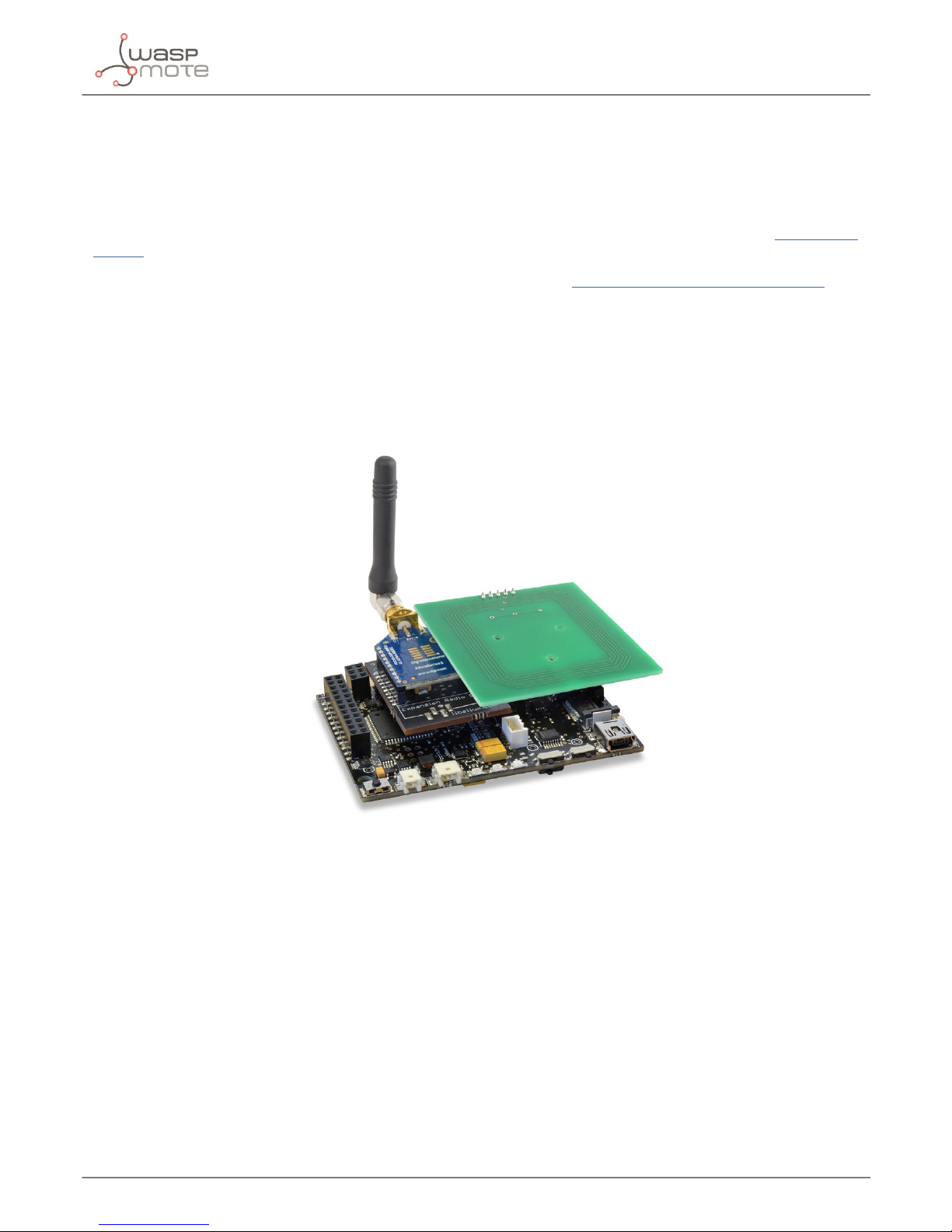
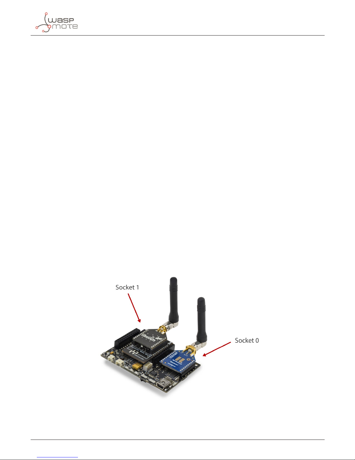
Figure : Waspmote with RFID/NFC module on socket 0 (below antenna) and ZigBee radio on socket 1
An RFID card can be understood as a remote storage unit where we can read and write information without contact. Most of the
RFID tags are passive, which implies that the RFID module must create an electromagnetic eld in order to power the tag. The
RFID card’s antenna (in fact it is an inductive coupler) gets the power from this eld. Also, an RFID card has a very basic microcontroller which manages the communications and memory access.
Many RFID standards have been released by the industry. Most of them have as operating frequency 13.56 MHz or 125 kHz. In
the present document we will be explaining the RFID/NFC module, which works at 13.56 MHz.
In particular, Libelium has created an ISO/IEC 14443-A and NFC compliant module for Waspmote. The ISO/IEC 14443-A protocol
is widely accepted as the de facto RFID at 13.56 MHz standard. Billions of ISO/IEC14443-A cards have been sold over the world.
NFC (Near Field Communication) is an extension of RFID which focuses on communications between smartphones and other
advanced devices. NFC is a set of standards based on previous RFID protocols like ISO/IEC 14443-A.
There are basically 3 ways to interact with an RFID card; Libelium’s RFID/NFC module allows the developer to implement the 3 of them:
1. the RFID/NFC module reads the RFID card’s unique identication (UID)
2. the RFID/NFC module reads the RFID card’s internal memory (16 bytes each time)
3. the RFID/NFC module writes in the RFID card’s internal memory (16 bytes each time)
-5-
v7.0
Introduction
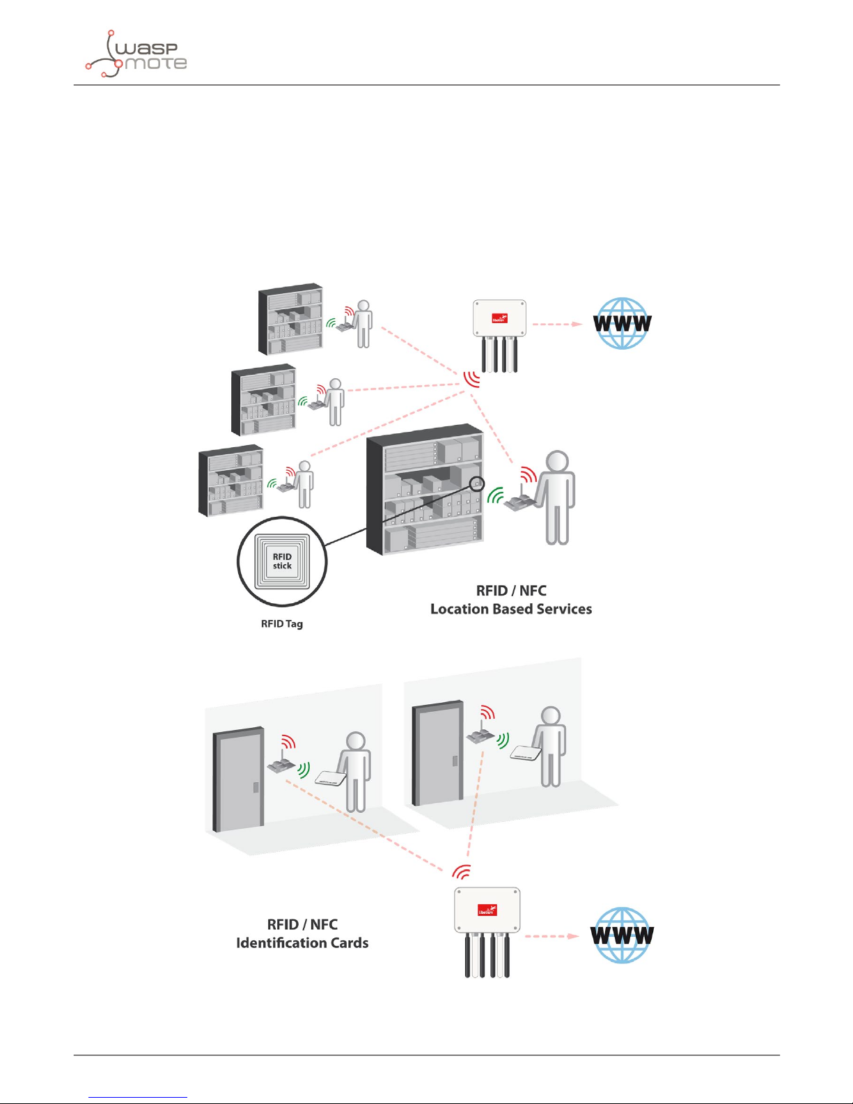
Among the RFID/NFC applications, the most common are:
• access control/security
• events ticketing
• public transport
• equipment and personnel tracking
• logistics
• real-time inventories
• marketing information (kiosks)
Figure : Some application examples
-6-
v7.0
Hardware
2. Hardware
Libelium’s RFID/NFC module integrates an RFID/NFC reader/writer integrated circuit.
Features
• Compatibility: Reader/writer mode supporting ISO 14443A / MIFARE / FeliCaTM / NFCIP-1
• Distance: 5cm
• Max capacity: 4KB
• Tags: cards, keyrings, stickers
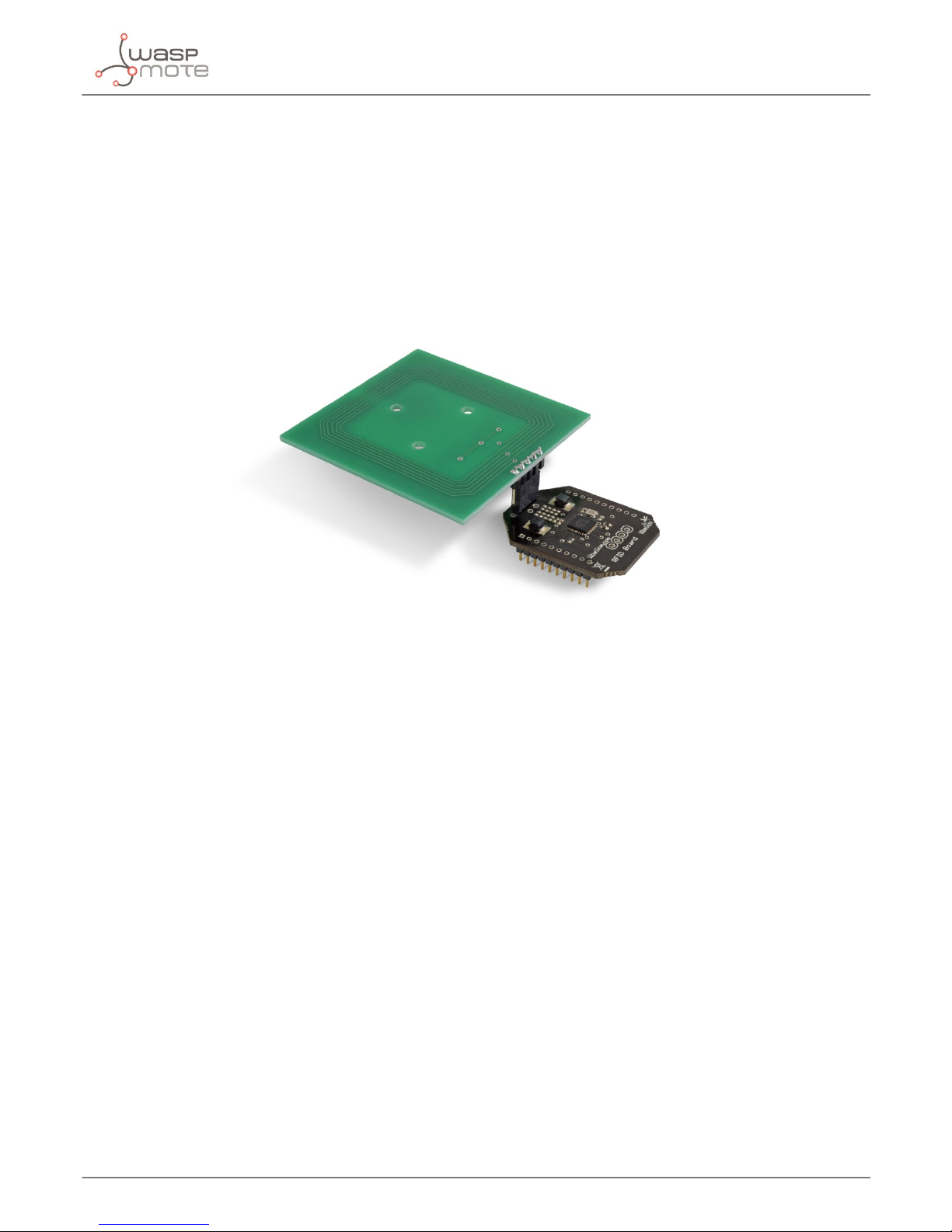
Figure : RFID/NFC module for 13.56 MHz and antenna
Among several RFID standards; Libelium’s RFID/NFC module is compliant with ISO/IEC 14443-A/Mifare®, which probably are
the most successful international standards in RFID technology. Mifare® is a proprietary technology by NXP which is based on
the ISO/IEC 14443-A standard. This technology operates at the 13.56 MHz ISM frequency band, so it can be deployed anywhere
without authorization or license.
The RFID/NFC module implements the radio-frequency, analog and digital tasks in transmission and reception, while Waspmote’s
role is to control these operations. Waspmote is connected to the RFID/NFC module through its UART interface.
The ISO/IEC 14443-A/Mifare® standard oers a 3-pass authentication method to enable secure, encrypted communications
between the RFID/NFC module and the card. Also, there are dierent mechanisms (CRC, parity, bit encoding, etc) to ensure the
data integrity.
The RFID/NFC module is also compatible with NFC, in particular with the standards ISO/IEC 18098 and NFCIP-1. The NFC
technology allows two-way communications between end-points that normally are smartphones or other advanced electronic
devices. An NFC communication can be set in a very quick way, which is a benet with regard to WiFi or Bluetooth.
The antenna is 57x57x10 mm and can be plugged in 2 directions, but for the best range we suggest to place it like in the photos,
standing out of the surface of Waspmote. Obviously, for projects with strict form factor specications, the antenna can be placed
over Waspmote. The antenna has a gain of around 33 dB and is congurable by the user.
-7-
v7.0
Dual radio with the Expansion Board
3. Dual radio with the Expansion Board
Before starting to use a module, it needs to be initialized. During this process, conguration parameters are sent to the module.
USB and SD card are also initialized.
3.1. Expansion Radio Board
The Expansion Board allows to connect two communication modules at the same time in the Waspmote sensor platform. This
means a lot of dierent combinations are possible using any of the wireless radios available for Waspmote: 802.15.4, ZigBee,
DigiMesh, 868 MHz, 900 MHz, LoRa, WiFi, GPRS, GPRS+GPS, 3G, 4G, Sigfox, LoRaWAN, Bluetooth Pro, Bluetooth Low Energy and
RFID/NFC. Besides, the following Industrial Protocols modules are available: RS-485/Modbus, RS-232 Serial/Modbus and CAN
Bus.
Some of the possible combinations are:
• LoRaWAN - GPRS
• 802.15.4 - Sigfox
• 868 MHz - RS-485
• RS-232 - WiFi
• DigiMesh - 4G
• RS-232 - RFID/NFC
• WiFi - 3G
• CAN bus - Bluetooth
• etc.
Remark: GPRS, GPRS+GPS, 3G and 4G modules do not need the Expansion Board to be connected to Waspmote. They can be plugged
directly in the socket1.
Next image shows the sockets available along with the UART assigned. On one hand, SOCKET0 allows to plug any kind of radio
module through the UART0. On the other hand, SOCKET1 permits to connect a radio module through the UART1.
Figure : Waspmote with XBee radio on socket 0 and Bluetooth module on socket 1

-8-
v7.0
Dual radio with the Expansion Board
This API provides a function in order to initialize the RFID/NFC module called RFID13.ON(socket). This function supports a
new parameter which permits to select the socket. It is possible to choose between socket0 or socket1.
An example of use the initialization function is the following:
• Selecting socket0: RFID13.ON(SOCKET0);
• Selecting socket1: RFID13.ON(SOCKET1);
The rest of functions are used the same way as they are used with older API versions. In order to understand them we recommend
to read this guide.
Warnings:
• Warnings:
• Avoid to use DIGITAL7 pin when working with the Expansion Board. This pin is used for setting the XBee into sleep mode.
• Avoid to use DIGITAL6 pin when working with the Expansion Board. This pin is used as power supply for the Expansion
Board.
• Incompatibility with Sensor Boards:
- Agriculture v30 and Agriculture PRO v30: Incompatible with Watermark and solar radiation sensors
- Events v30: Incompatible with interruption shift register
- Gases v30: DIGITAL6 is incompatible with CO2 (SOCKET_2) and DIGITAL7 is incompatible with NO2 (SOCKET_3)
- Smart Water v30: DIGITAL7 incompatible with conductivity sensor
- Smart Water Ions v30: Incompatible with ADC conversion (sensors cannot be read if the Expansion Board is in use)
- Gases PRO v30: Incompatible with SOCKET_2 and SOCKET_3
- Cities PRO v30: Incompatible with SOCKET_3. I2C bus can be used. No gas sensor can be used.
3.2. Setting on
With the function ON() module is powered and the UART is opened to communicate with the module. It also enters in command
mode and sets some default congurations.
// switches ON the RFID/NFC module using expansion board
RFID13.ON(SOCKET1);
3.3. Setting o
The RFID/NFC API function OFF() exits from the radio RFID/NFC command-mode securely, closes the UART and switches the
module o.
// closes the UART and powers off the module
RFID13.OFF();
-9-
v7.0
RFID Tags
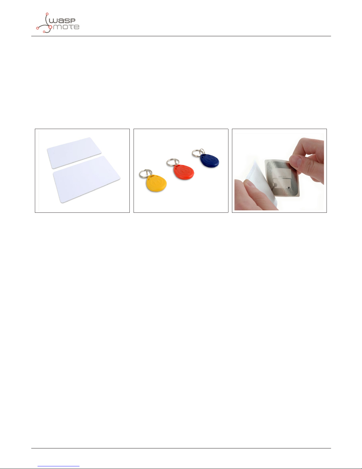
4. RFID Tags
Libelium oers Mifare® Classic 1k cards tags and stickers along with the Waspmote RFID/NFC module. More than 3.5 billions of
this type of cards have been sold around the world up now.
An RFID card has a thin form factor (81x54x1 mm), like a driving license or identication card, and can be kept in the user’s wallet.
However, an RFID tag is smaller and thicker (around 20x20x5 mm) but can be kept in the user’s keyring. Last, an RFID sticker has
an intermediate size (50x50) and it is really thin and exible. Of course, a sticker can be stuck in any object so it focuses on the
Internet of Things (IoT) and logistics applications.
It is important to note that a card always has a longer range than a tag or sticker because the antenna of a card has more surface.
Figure : RFID cards Figure : RFID keyrings Figure : RFID sticker
A Mifare® Classic 1k card has 1024 bytes of internal storage capacity, divided into 16 sectors. Each sector is composed of 4 blocks, and
each block is composed of 16 bytes. That is to say, each card has 64 blocks, from number 0 to 63. Let’s describe the structure of a card:
1. In each sector, the last block (blocks number 3, 7, 11..) is called the sector trailer. This block stores the 2 keys or passwords
and controls the access to the rest of the blocks in the sector (e.g. block number 7 controls block 4, 5 and 6). The rst 6 bytes
(0..5) are the key A, and the last 5 bytes (10..15) are the key B. As we will see, before reading or writing in any block, we must
rst authenticate us to that sector by providing one of the two keys (normally the A key). The bytes number 6, 7 and 8 store
the control bytes, which control the way the the blocks may be accessed (read/write). Byte number 9 is not dened in all
sector trailers.
2. The very rst block (number 0) is called the manufacturer block and has special characteristics. The rst 4 bytes (0..3) are the
unique identication (UID). The UID can be seen as the serial number of the card and identify the card in a unequivocal way
(read more in the “Security with RFID/NFC at 13.56 MHz” chapter). The next byte (number 4) is the CRC check byte so it can
be used to check the correct read; it is calculated with the XOR of the 4-byte UID. The rest of the bytes in the block number
0 (bytes 5..15) are the manufacturer data. This block 0 has read-only access for security reasons. We need to authenticate
before reading the block number 0 but the UID can be obtained anyway, without the key.
3. The rest of the blocks (1 and 2; 4, 5 and 6; 8, 9 and 10; etc) are known as data blocks and they are available to read and write
operations, after the needed authentication process.
To sum up, the Mifare® 1k cards have a net storage capacity of:
(16 sectors/card x 3 data blocks/sector X 16 bytes/block) – 16 bytes (rst block) = 752 bytes/card
The cards have been tested to conserve data for 10 years and to have a write endurance of 100,000 cycles.
 Loading...