

Page 1
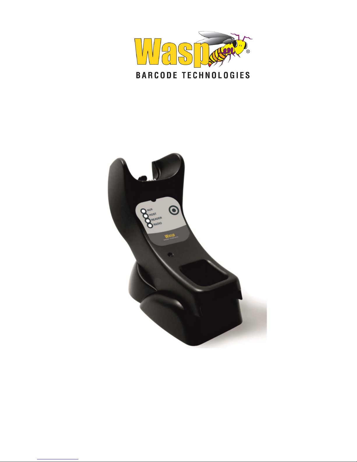
Wasp WWS750-BS
Base Station
Quick Reference Guide
Page 2

Wasp Barcode Technologies
1400 10th Street
Plano, Texas USA 75074
Telephone: (214) 547-4100
©2018 Wasp Barcode Technologies
An Unpublished Work - All rights reserved. No part of the contents of this documentation or the procedures described therein may be reproduced or transmitted in any form or by any means without prior written permission of Wasp
Barcode Technologies or its subsidiaries or affiliates ("Wasp Technologies"
Technologies Wasp Technologies). Owners of WaspTechnologies products are
hereby granted a non-exclusive, revocable license to reproduce and transmit
this documentation for the purchaser's own internal business pur poses. Purchaser shall not remove or alter any proprietary notices, including copy right
notices, contained in this documentation and shall ensure that all notices
appear on any reproductions of the documentation.
Should future revisions of this manual be published, you can acquire printed
versions by contacting your Wasp Technologies representative. Electronic versions may either be downloadable from the Wasp Technologies website
(www.waspbarcode.com
) or provided on appropriate media. If you visit our
website and would like to make comments or suggestions about this or other
Wasp Technologies publications, please let us know via the "Contact
WaspTechnologies" page.
Disclaimer
Wasp Technologies has taken reasonable measures to provide information in
this manual that is complete and accurate, however, Wasp Technologies
reserves the right to change any specification at any time without prior notice.
Wasp Technologies and the Wasp Technologies logo are registered trademarks
of Wasp Technologies Barcode Technologies in many countries, including the
U.S.A. and the E.U. Duraline is a trademark of Wasp Barcode Technologies registered in many countries, including the U.S.A. and the E.U. All other brand and
product names may be trademarks of their respective owners.
Patents
This product is covered by one or more of the following patents:
Design patents: EP002577189, USD757732, ZL201530128521.0
Utility patents: EP1873886B1, US7948214, ZL200780030808.2.
.
Page 3

Table of Contents
Using the WWS750-BS Base Station ........................................................... 1
Installation ....................................................................................................... 2
Regulating the Cradle Position .............................................................. 2
Mounting with the Metal Plate ............................................................. 4
System Connections ....................................................................................... 5
Connecting and Disconnecting the Interface Cable ............................ 5
WWS750-BS Configuration ............................................................................ 7
Serial Configuration ................................................................................ 7
Configuration Bar Codes ........................................................................ 7
Resetting Standard Product Defaults .................................................. 7
Selecting the Interface Type .......................................................................... 8
Configuring the Interface ............................................................... 8
Keyboard Interface ....................................................................... 10
Scancode Tables............................................................................ 11
Country Mode ........................................................................................ 12
Caps Lock State ..................................................................................... 16
Numlock ................................................................................................. 17
Technical Features ........................................................................................ 18
Wasp Technologies Limited Factory Warranty ......................................... 20
Ergonomic Recommendations .................................................................... 21
Services and Support .................................................................................... 21
Page 4

Page 5
Quick Reference Guide 1
Using the WWS750-BS Base Station
The WWS750-BS Presentation Base, when paired with one or more WWS750
reader, builds a Cordless Reading System for the collection, decod- ing and
transmission of bar code data. It can be connected to a Host PC via RS-232,
USB, or KBD Wedge, and is suited for single-cradle layouts.
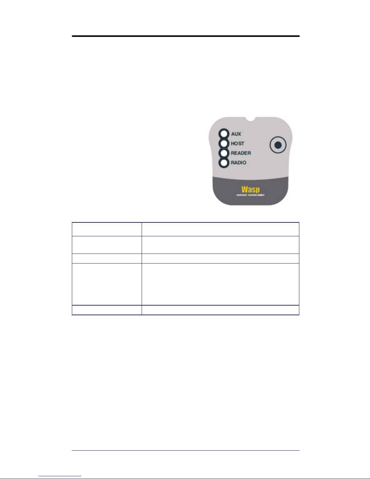
The label on the cradle contains LED indicators and a multi-function button.
The LEDs signal the WWS750-BS status, as shown.
LED STATUS
Aux
Yellow On = WWS750-BS is powered through an external
power supply.
Host Yellow On = WWS750-BS is powered by the Host.
Reader
Green On = the reader battery is completely charged.
Red On = the reader battery is charging.
Orange Blinking = reader battery fault - replace battery.
Red / Green Alternatively Blinking = charging error - see PRG.
Off = reader not in the cradle or not properly inserted.
Radio Yellow Blinking = radio activity.
Page 6
Installation
2 WWS750-BS Base Station
Installation
To set up your WWS750-BS cradle you must:
1. Physically install the cradle.
2. Make all system connections.
3. Configure the WWS750-BS cradle.
The cradle package contains the following items:
Regulating the Cradle Position
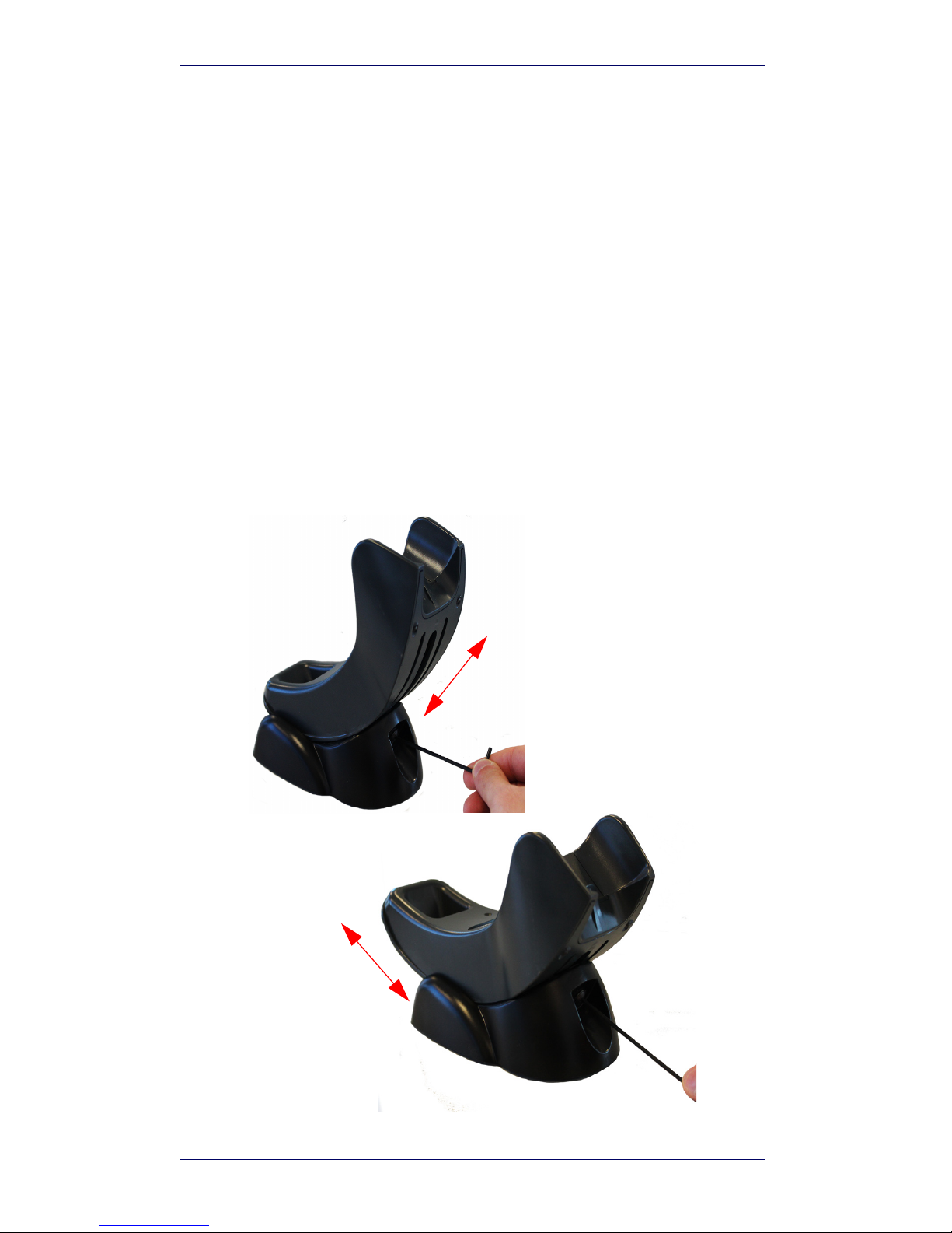
To regulate the position, use the hex key to unscrew the holder and slide it to
the desired position.
• WWS750-BS Presentation Base • Hex Key
• WWS750-BS Quick Reference Guide
(this manual)
• Rubber Spacers
• Metal Mounting Plate
Page 7
Installation
Quick Reference Guide 3
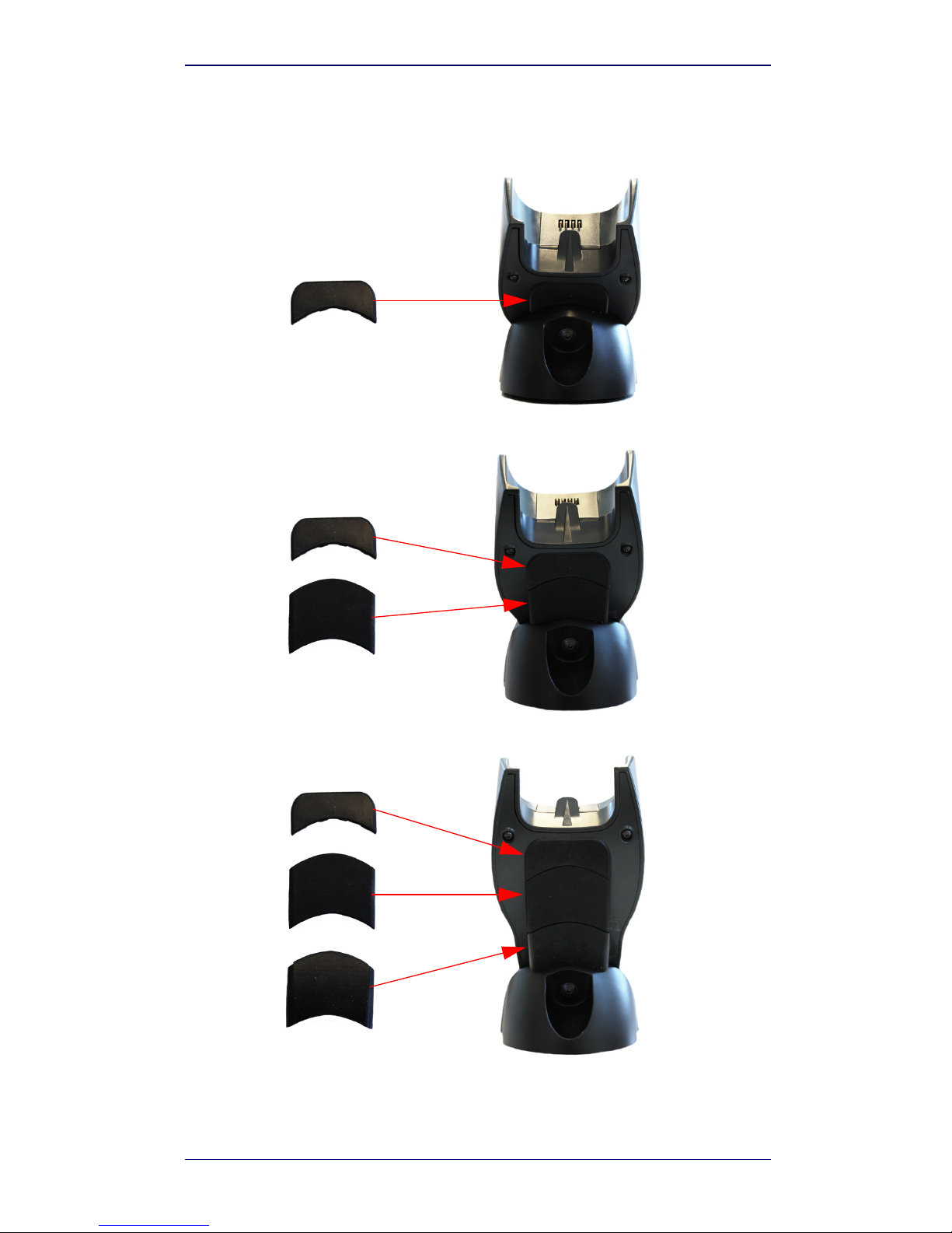
The rubber spacers included in the box can be used to fix the position of the
cradle:
Page 8
Installation
4 WWS750-BS Base Station
Mounting with the Metal Plate
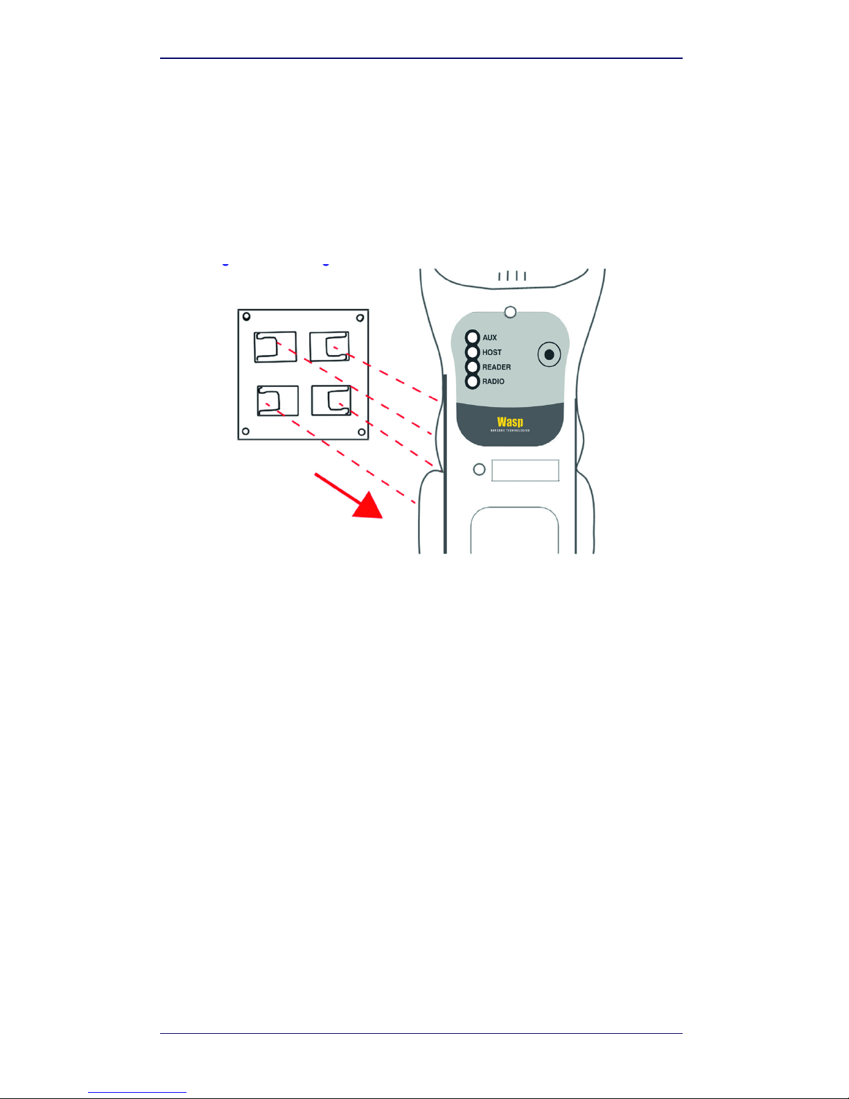
1. Affix the metal plate onto the desired mounting surface using the
two center screw holes (see Figure 1 on page 4).
2. Slide the tabs on the back of the cradle onto the metal plate as
shown in Figure 1.
3. After aligning the tabs, push up to lock into place.
Figure 1. Mounting Plate on Wall
Page 9
System Connections
Quick Reference Guide 5
System Connections
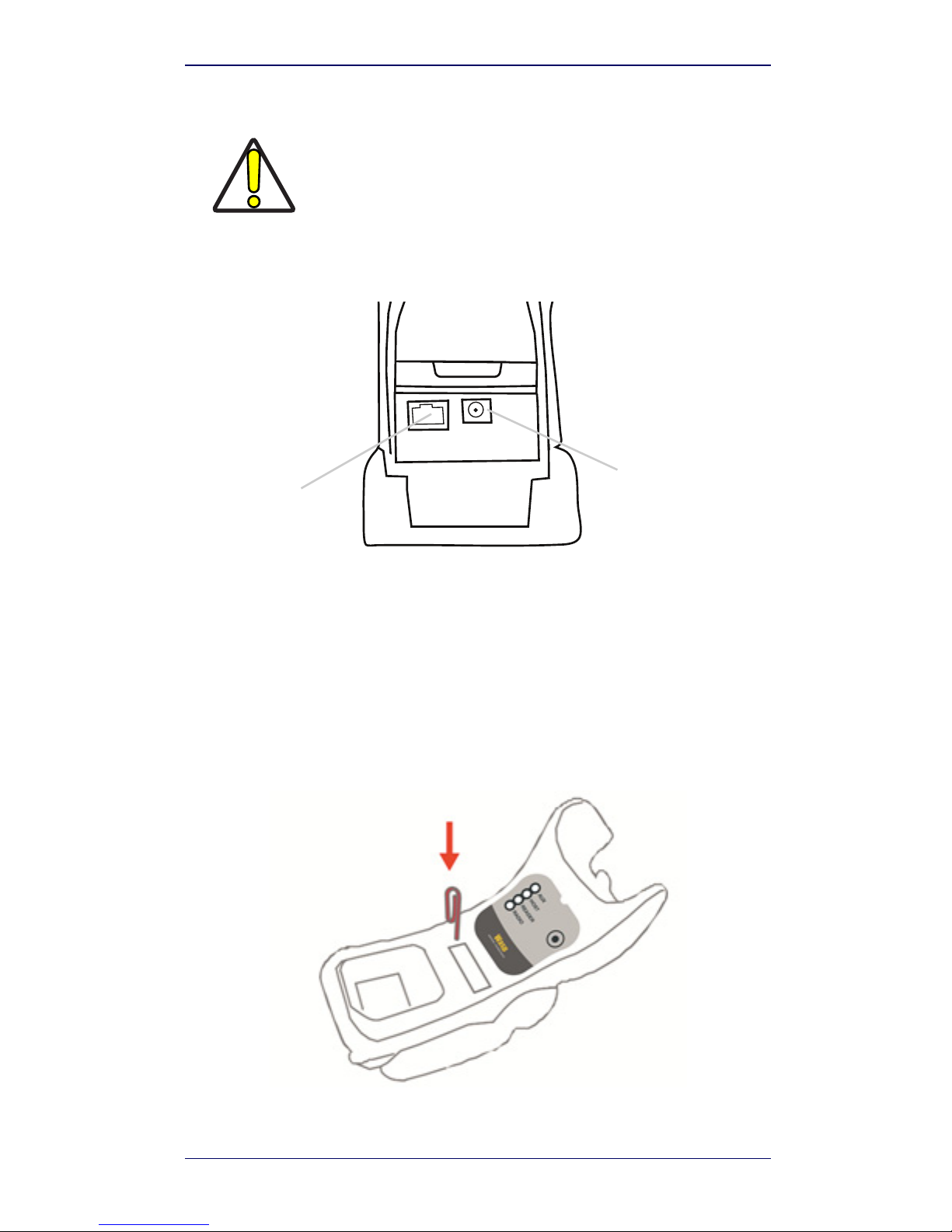
The WWS750-BS cradle provides a multi-interface connector and a power
supply connector as shown:
Connecting and Disconnecting the Interface Cable
The WWS750-BS can be connected to a Host by means of a multi-interface
cable, which must be simply plugged into the Host connector, visible on the
front panel of the cradle.
To disconnect the cable, insert a paper clip or other similar object into the hole
corresponding to the Host connector on the body of the cradle. Push down on
the clip while unplugging the cable. Refer to the following figure:
CAUTION
Connections should always be made with power off!
Power Supply
Multi-Interface
Connector
Connecting/Disconnecting the Cable
Page 10
System Connections
6 WWS750-BS Base Station
RS-232
USB
NOTE
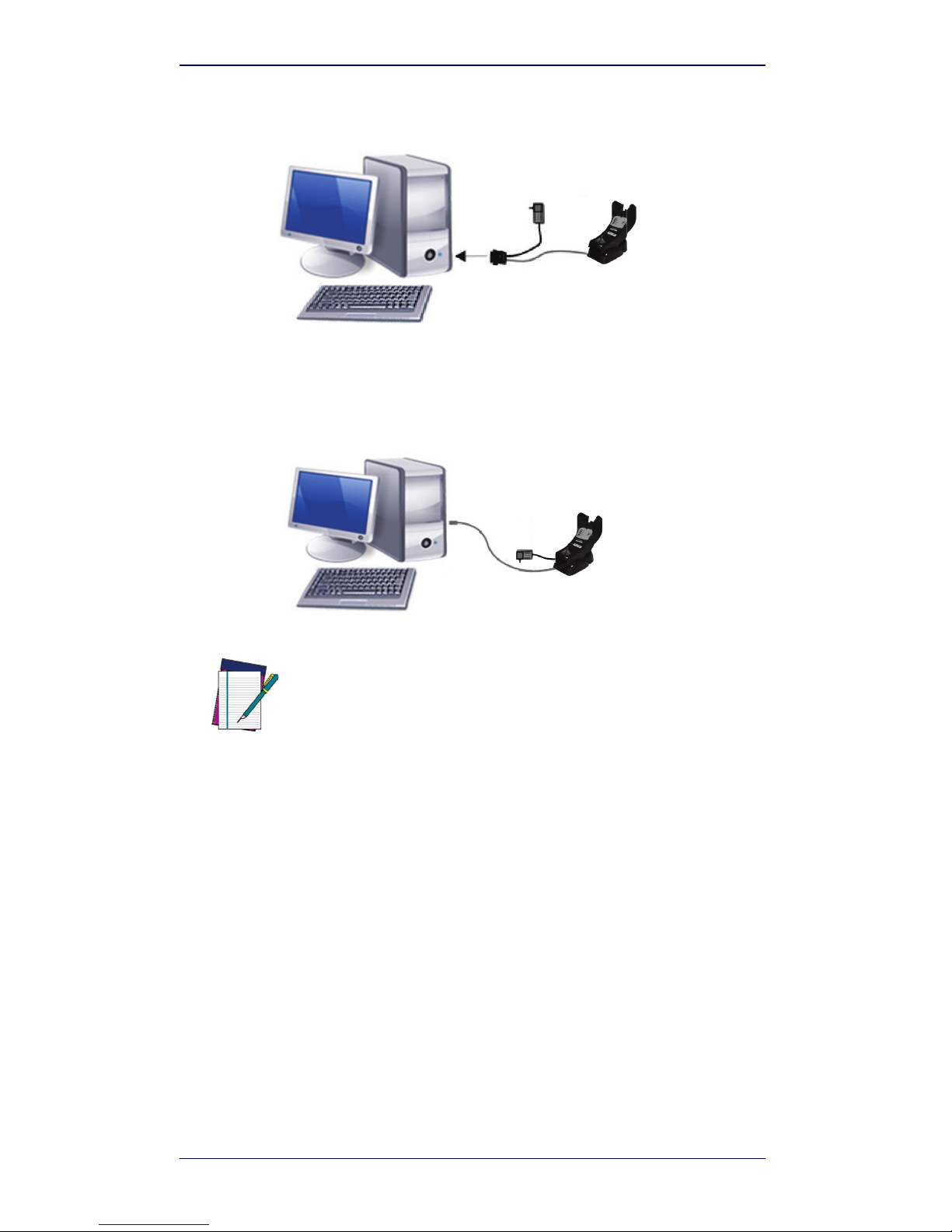
The power supply is required only if you need to connect the interface
cable to a standard USB Port. The power supply is not required if you
connect the interface cable to a PoweredUSB 12V or 24V port.
Page 11
WWS750-BS Configuration
Quick Reference Guide 7
WWS750-BS Configuration
The WWS750-BS configuration can be performed in two ways: sending configuration strings from the Host PC via the RS-232 or USB-COM interface or
by reading configuration bar codes with the WWS750.
Serial Configuration
By connecting the WWS750-BS to a PC through an RS-232 or USB-COM interface cable it is possible to send configuration strings from the PC to
WWS750-BS.
Configuration Bar Codes
Link the cradle and the reader using the procedures described in the WWS750
Quick Reference. Once the pairing is complete, you can configure the
WWS750-BS cradle by reading configuration bar codes in this manual.
To configure the WWS750-BS using the WWS750 reader (paired to the cradle
with the Bind command), follow the procedure according to the interface
selected.
Resetting Standard Product Defaults
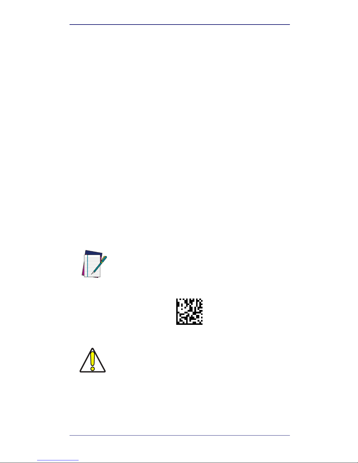
Reference the PRG for a listing of standard factory settings. If you aren’t sure
what programming options are in your reader, or you’ve changed some
options and want the factory settings restored, scan the
Standard Product
Default Settings
bar code below to copy the factory configuration for the cur-
rently active interface to the current configuration.
NOTE
Factory defaults are based on the interface type. Configure the reader
for the correct interface before scanning this label.
CAUTION
Scanning this bar code will RESET all settings for the WWS750. Any
customized settings that may have been applied to the reader will be
lost.
Standard Product Default Settings
Page 12
Selecting the Interface Type
8 WWS750-BS Base Station
Selecting the Interface Type
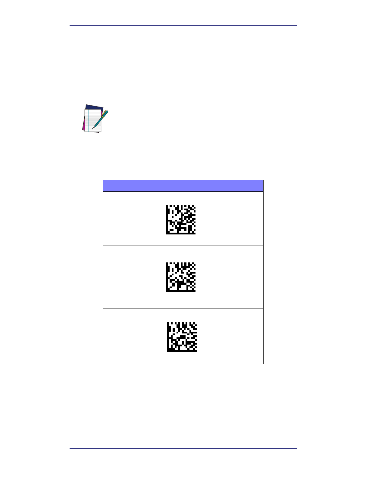
Upon completing the physical connection between the reader and its host,
scan the appropriate bar code for your system’s correct interface type.
Configuring the Interface
Scan the programming bar code which selects the appropriate interface type
for the system the reader will be connected to.
NOTE
Unlike some other programming features and options, interface selections require that you scan only one programming bar code label. DO
NOT scan an ENTER/EXIT bar code prior to scanning an interface selection bar code.
Some interfaces require the scanner to start in the disabled state when
powered up. If additional scanner configuration is desired while in this
state, pull the trigger and hold for 5 seconds. The scanner will change
to a state that allows programming with bar codes.
RS-232
RS-232 standard interface
Select RS232-STD
RS-232 Wincor-Nixdorf
Select RS232-WN
RS-232 for use with OPOS/UPOS/JavaPOS
Select RS-232 OPOS
Page 13
Selecting the Interface Type
Quick Reference Guide 9
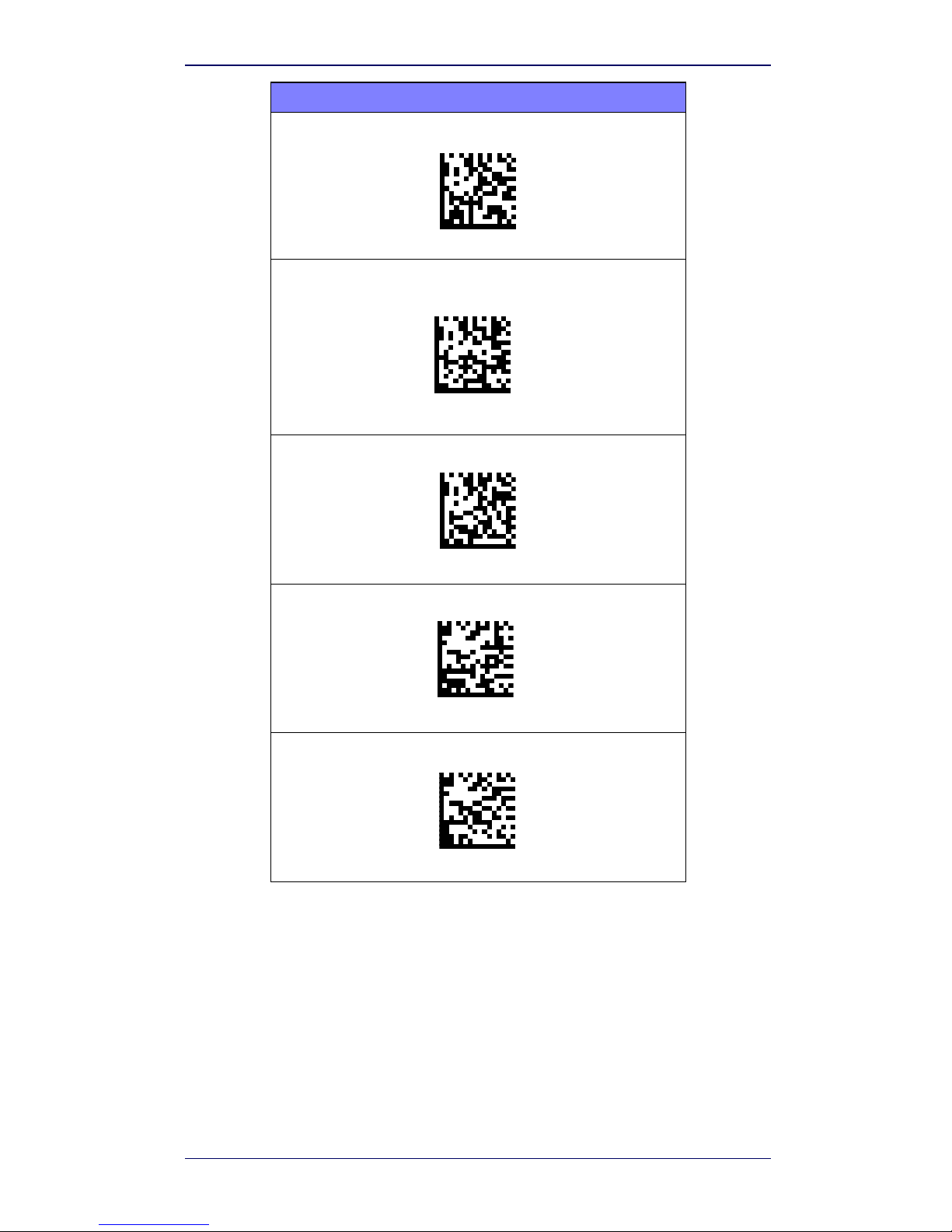
USB
USB COM to simulate RS-232 standard interface
USB-COM-STD
a
USB-OEM
(can be used for OPOS/UPOS/JavaPOS)
USB-OEM
USB Keyboard with standard key encoding
Select USB Keyboard
USB Keyboard with alternate key encoding
USB Alternate Keyboard
USB Keyboard for Apple computers
USB-KBD-APPLE
a. Download the correct USB COM driver from www.waspbarcode.com.
Page 14
Selecting the Interface Type
10 WWS750-BS Base Station
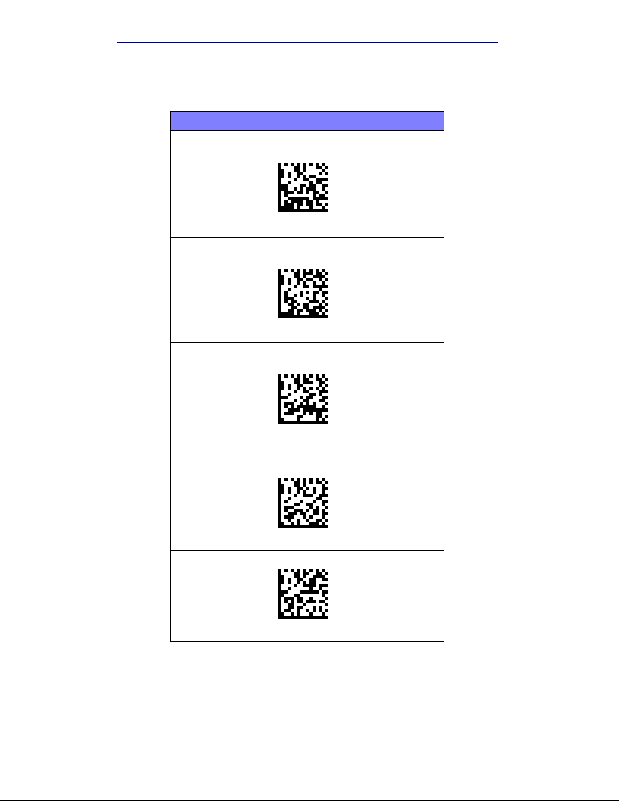
Keyboard Interface
Use the programming bar codes to select options for
USB Keyboard and Wedge Interfaces.
KEYBOARD
AT, PS/2 25-286, 30-286, 50, 50Z, 60, 70, 80, 90 & 95 w/
Standard Key Encoding
Select KBD-AT
Keyboard Wedge for IBM AT PS2 with standard key encoding
but without external keyboard
Select KBD-AT-NK
AT, PS/2 25-286, 30-286, 50, 50Z, 60, 70, 80, 90 & 95
w/Alternate Key
Select KBD-AT-ALT
Keyboard Wedge for IBM AT PS2 with alternate key encoding
but without external keyboard
Select KBD-AT-ALT-NK
PC/XT w/Standard Key Encoding
Select KBD-XT
Page 15
Selecting the Interface Type
Quick Reference Guide 11
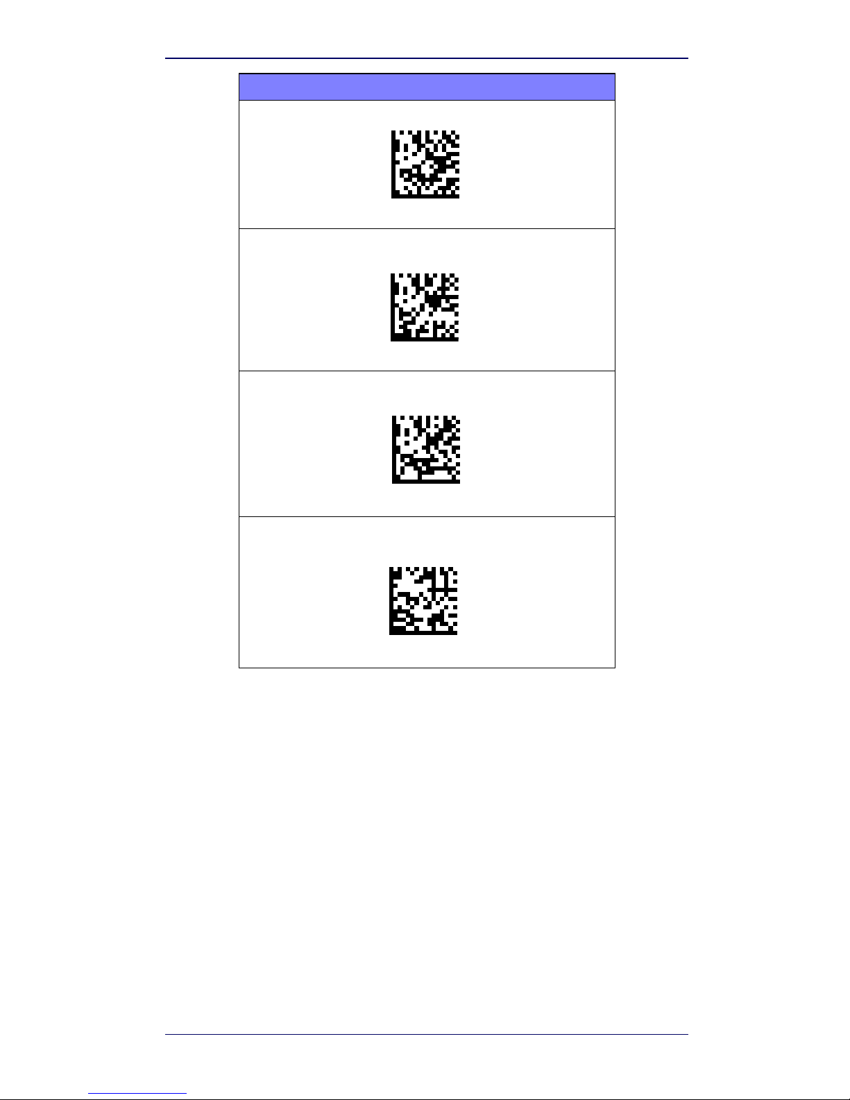
Scancode Tables
Reference the WWS750 QRG for information about control character emulation which applies to keyboard interfaces.
KEYBOARD (continued)
Keyboard Wedge for IBM Terminal 3153
Select KBD-IBM-3153
Keyboard Wedge for IBM Terminals 31xx, 32xx, 34xx, 37xx make
only keyboard
Select KBD-IBM-M
Keyboard Wedge for IBM Terminals 31xx, 32xx, 34xx, 37xx make
break keyboard
Select KBD-IBM-MB
Keyboard Wedge for DIGITAL Terminals
VT2xx, VT3xx, VT4xx
Select KBD-DIG-VT
Page 16
Selecting the Interface Type
12 WWS750-BS Base Station
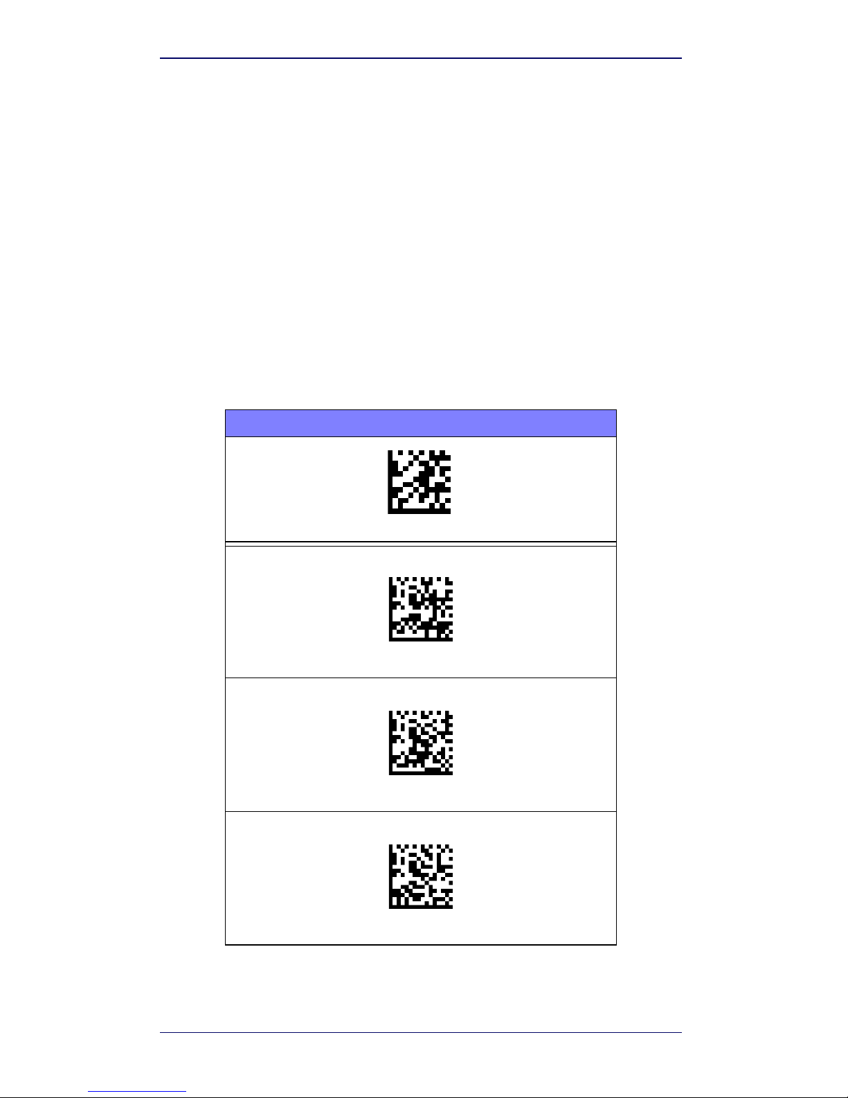
Country Mode
This feature specifies the country/language supported by the keyboard. Only
these interfaces support ALL Country Modes:
• USB Keyboard (without alternate key encoding)
• AT, PS/2 25-286, 30-286, 50, 50Z, 60, 70, 80, 90 & 95 w/Std Key
Encoding
• Keyboard Wedge for IBM AT PS2 with standard key encoding but
without external keyboard
• AT, PS/2 25-286, 30-286, 50, 50Z, 60, 70, 80, 90 & 95 without Alternate Key
• Keyboard Wedge for IBM AT PS2 without alternate key encoding but
without external keyboard
All other interfaces support ONLY the following Country Modes: U.S., Belgium,
Britain, France, Germany, Italy, Spain, Sweden.
COUNTRY MODE
ENTER/EXIT PROGRAMMING MODE
Country Mode = U.S.
Country Mode = Belgium
Country Mode = Britain
*
Supports only the interfaces listed in the Country Mode feature
description
Page 17
Selecting the Interface Type
Quick Reference Guide 13
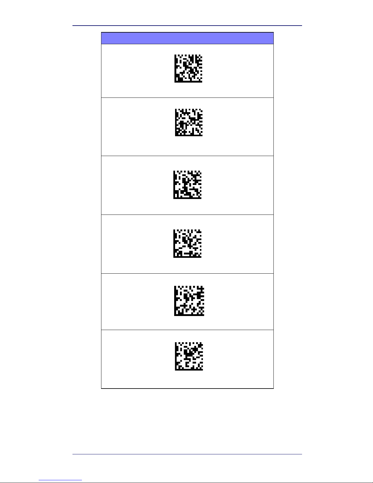
COUNTRY MODE (continued)
Country Mode = Croatia*
Country Mode = Czech Republic*
Country Mode = Denmark*
Country Mode = France
Country Mode = French Canadian
Country Mode = Germany
*
Supports only the interfaces listed in the Country Mode feature
description
$CKBCO13(CR)
Page 18
Selecting the Interface Type
14 WWS750-BS Base Station
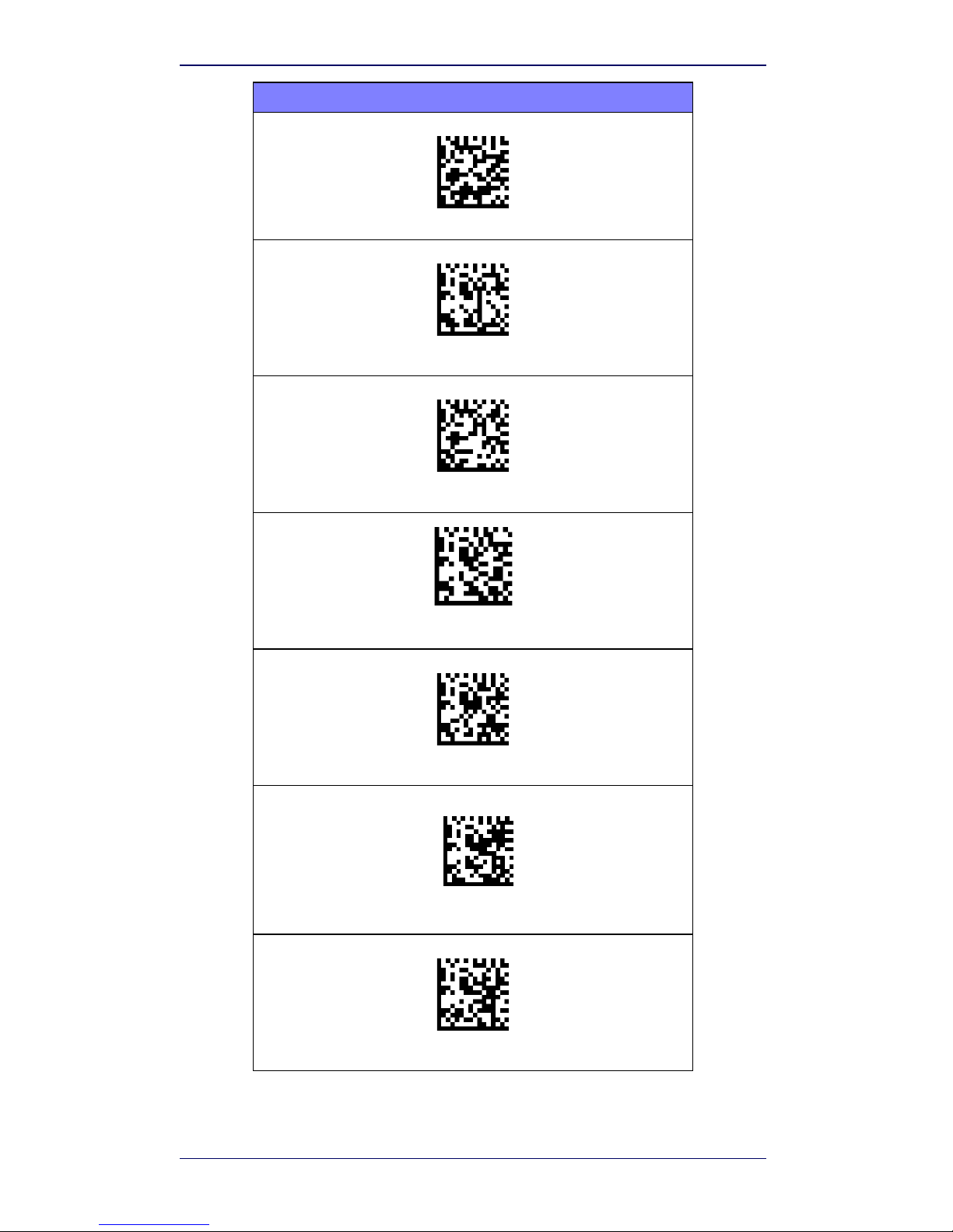
COUNTRY MODE (continued)
Country Mode = Hungary*
Country Mode = Italy
Country Mode = Japanese 106-key*
Country Mode = Lithuanian
Country Mode = Norway*
Country Mode = Poland*
Country Mode = Portugal*
*
Supports only the interfaces listed in the Country Mode feature
description
$CKBCO14(CR)
Page 19
Selecting the Interface Type
Quick Reference Guide 15
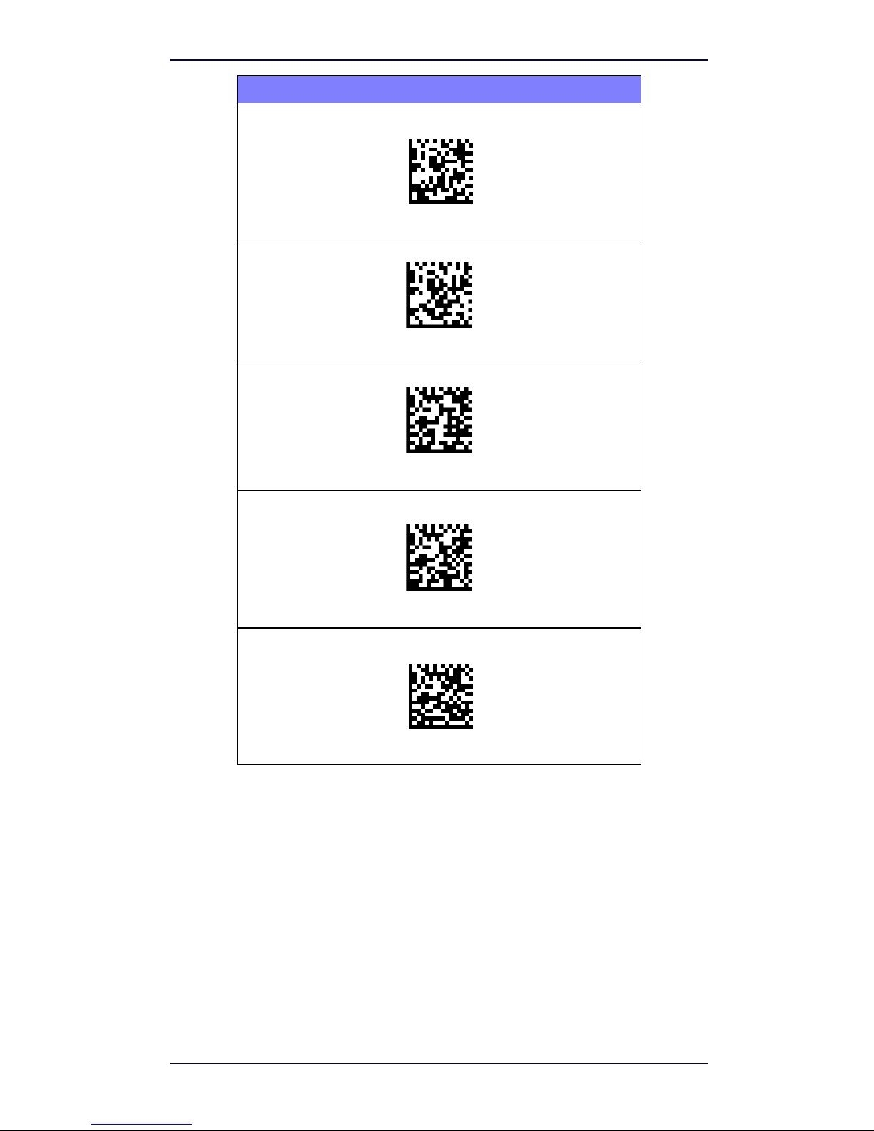
COUNTRY MODE (continued)
Country Mode = Romania*
Country Mode = Spain
Country Mode = Sweden
Country Mode = Slovakia*
Country Mode = Switzerland*
*
Supports only the interfaces listed in the Country Mode feature
description
Page 20
Selecting the Interface Type
16 WWS750-BS Base Station
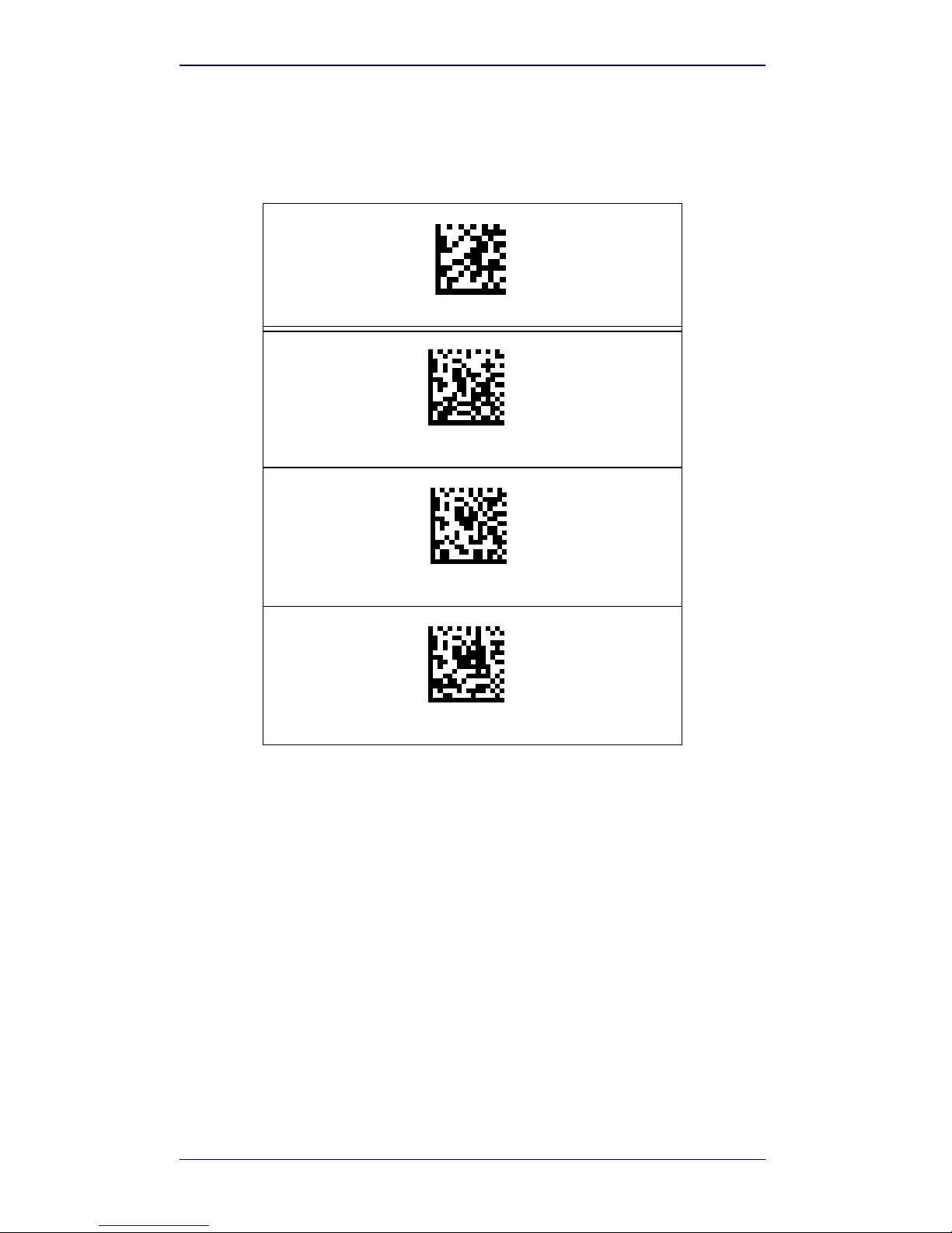
Caps Lock State
This option specifies the format in which the reader sends character data.
This applies to keyboard wedge interfaces. This does not apply when an alternate key encoding keyboard is selected.
ENTER/EXIT PROGRAMMING MODE
Caps Lock State = Caps Lock OFF
Caps Lock State = Caps Lock ON
Caps Lock State = AUTO Caps Lock Enable
Page 21
Selecting the Interface Type
Quick Reference Guide 17
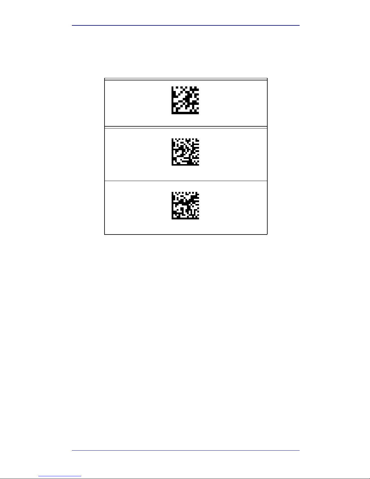
Numlock
This option specifies the setting of the Numbers Lock (Numlock) key while in
keyboard wedge interface. This only applies to alternate key encoding interfaces. It does not apply to USB keyboard.
ENTER/EXIT PROGRAMMING MODE
Numlock = Numlock key unchanged
Numlock = Numlock key toggled
Page 22
Technical Features
18 WWS750-BS Base Station
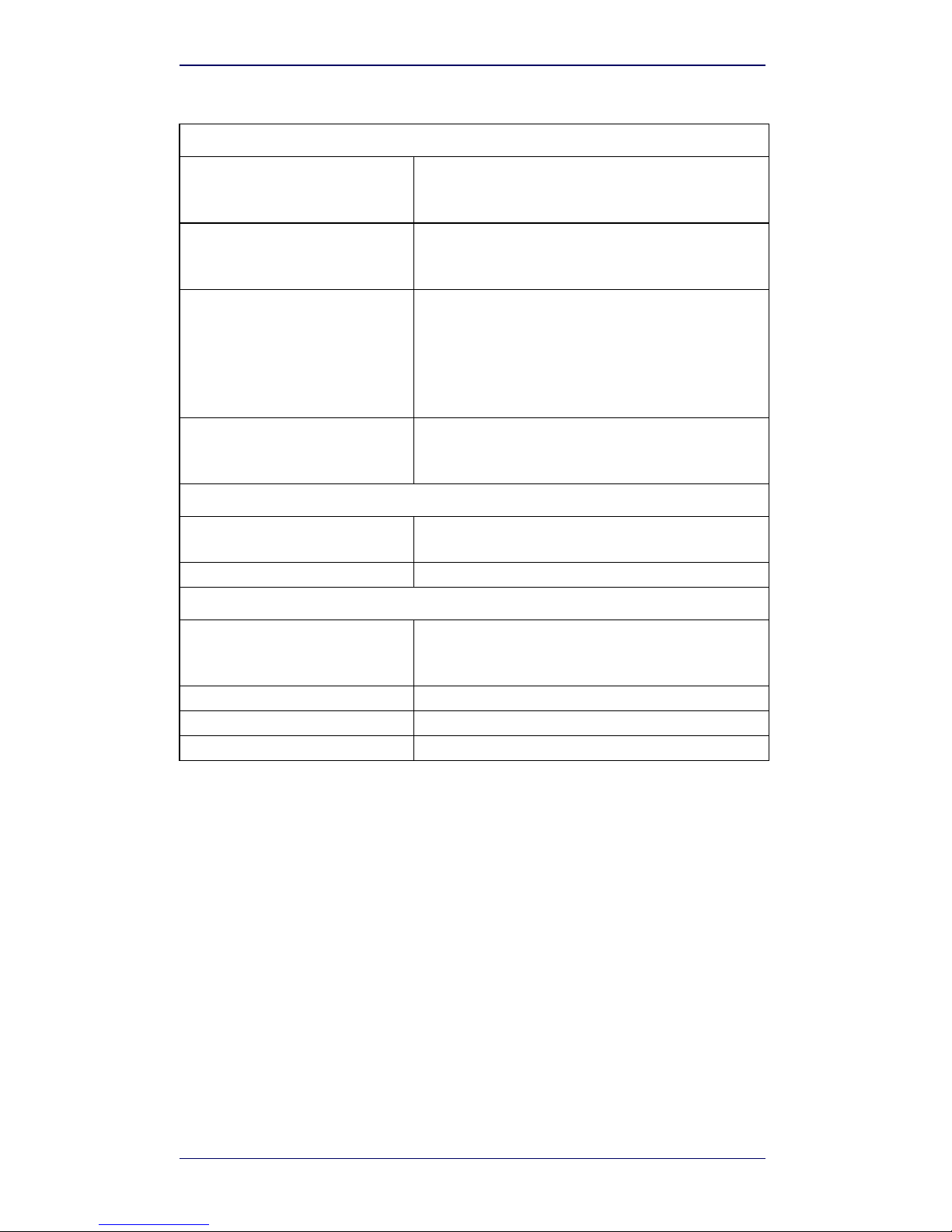
Technical Features
ELECTRICAL FEATURES
Supply Voltage
External Power
Host Power
10 - 30 VDC
(Powered USB or RS232)
Power Consumption
External Power
Host Power
max. 10 W (charging) *
max. 10 W (charging) *
Indicators
Ext. Power/Data yellow LED
Host Power/Data yellow LED
Reader batt. state green/red LED
Spare batt. state green/red LED
Radio yellow LED
Ethernet green LED (Ethernet models only)
Time of Recharge
External Power
Host Power
min. 3 hours with 2150 mAh Li-Ion battery
min. 3 hours with 2150 mAh Li-Ion battery
BLUETOOTH FEATURES
Protocol
Bluetooth 2.0; Class 1; SPP (Serial Port Profile) or HID
(Human Interface Device) profile
Radio Frequency 2.40 to 2.48 GHz
ENVIRONMENTAL FEATURES
Working Temperature
Radio
Battery Charging
-20° to +50
C / -4 to +122 °F
0° to +40 °C / +32° to +104 °F
Storage Temperature -20° to +70
C / -4 to +158 °F
Humidity 90% non condensing
Protection Class IP40
Page 23
Technical Features
Quick Reference Guide 19
* Having a switching regulator inside, the WWS750-BS draws the same
power, regardless of the supply voltage. i.e. as the input voltage increases
the current drawn decreases
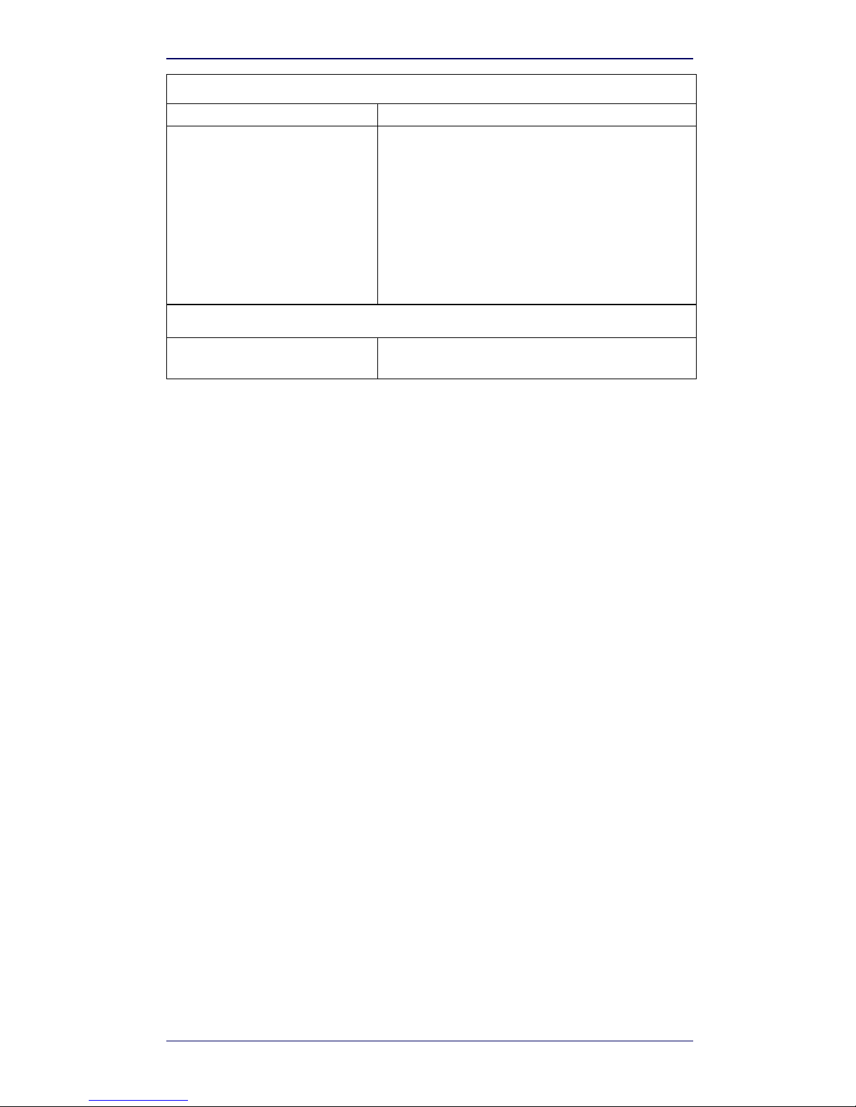
MECHANICAL FEATURES
Weight without metal plate 490gr
Dimensions (without antenna)
WHEN HORIZONTALLY POSITIONED:
Height 125mm
Length 215mm
Width 98mm
WHEN VERTICALLY POSITIONED:
Height 185mm
Length 85mm
Width 98mm
SYSTEM CONFIGURATION
Max number of devices per base
station
7
Page 24

Wasp Technologies Limited Factory Warranty
20 WWS750-BS Base Station
Wasp Technologies Limited Factory Warranty
Warranty Coverage
Wasp warranties this product against defects in workmanship and materials, for a period of
three years from the date of shipment, provided that the product is operated under normal
and proper conditions. Wasp hardware products are warranted against defects in material
and workmanship under normal and proper use. The liability of Wasp under this warranty is
limited to furnishing the labor and parts necessary to remedy any defect covered by this warranty and restore the product to its normal operating condition. Repair or replacement of
product during the warranty does not extend the original warranty term. Products are sold
on the basis of specifications applicable at the time of manufacture and Wasp has no obligation to modify or update products once sold.
If Wasp determines that a product has defects in material or workmanship, Wasp shall, at its
sole option repair or replace the product without additional charge for parts and labor, or
credit or refund the defective products duly returned to Wasp. To perform repairs, Wasp may
use new or reconditioned parts, components, subassemblies or products that have been
tested as meeting applicable specifications for equivalent new material and products. Customer will allow Wasp to scrap all parts removed from the repaired product. The warranty period shall extend from the date of shipment from Wasp for the duration published by Wasp
for the product at the time of purchase (Warranty period). Wasp warrants repaired hardware
devices against defects in workmanship and materials on the repaired assembly for a 90 day
period starting from the date of shipment of the repaired product from Wasp or until the expiration of the original warranty period, whichever is longer. Wasp does not guarantee, and
it is not responsible for, the maintenance of, damage to, or loss of configurations, data, and
applications on the repaired units and at its sole discretion can return the units in the “factory default” configuration or with any software or firmware update available at the time of
the repair (other than the firmware or software installed during the manufacture of the product). Customer accepts responsibility to maintain a back up copy of its software and data.
Refer to:
http://www.waspbarcode.com/support/warranty-claims
Warranty Claims:
http://www.waspbarcode.com/support/warranty-claims
Warranty Claims Process
In order to obtain service under the Factory Warranty, Customer must notify Wasp of the
claimed defect before the expiration of the applicable Warranty period and obtain from Wasp
a return authorization number (RMA) for return of the product to a designated Wasp service
center. If Wasp determines Customer’s claim is valid, Wasp will repair or replace product
without additional charge for parts and labor. Customer shall be responsible for packaging
and shipping the product to the designated Wasp service center, with shipping charges prepaid. Wasp shall pay for the return of the product to Customer if the shipment is to a location
within the country in which the Wasp service center is located. Customer shall be responsible
for paying all shipping charges, duties, taxes, and any other charges for products returned to
any other locations. Failure to follow the applicable RMA policy, may result in a processing
fee. Customer shall be responsible for return shipment expenses for products which Wasp,
at its sole discretion, determines are not defective or eligible for warranty repair.
Warranty Exclusions
The Wasp Factory Warranty shall not apply to:
(i) any product which has been damaged, modified, altered, repaired or upgraded by other
than Wasp service personnel or its authorized representatives;
(ii) any claimed defect, failure or damage which Wasp determines was caused by faulty
operations, improper use, abuse, misuse, wear and tear, negligence, improper storage
or use of parts or accessories not approved or supplied by Wasp;
(iii) any claimed defect or damage caused by the use of product with any other instrument,
equipment or apparatus;
(iv) any claimed defect or damage caused by the failure to provide proper maintenance,
including but not limited to cleaning the upper window in accordance with product
manual;
Page 25

Ergonomic Recommendations
Quick Reference Guide 21
(v) any defect or damage caused by natural or man-made disaster such as but not limited
to fire, water damage, floods, other natural disasters, vandalism or abusive events that
would cause internal and external component damage or destruction of the whole
unit, consumable items;
(vi) any damage or malfunctioning caused by non-restoring action as for example firm-
ware or software upgrades, software or hardware reconfigurations etc.;
(vii) the replacement of upper window/cartridge due to scratching, stains or other degra-
dation and/or
(viii) any consumable or equivalent (e.g., cables, power supply, batteries, keypads, touch
screen, triggers etc.).
No Assignment
Customer may not assign or otherwise transfer its rights or obligations under this warranty
except to a purchaser or transferee of product. No attempted assignment or transfer in violation of this provision shall be valid or binding upon Wasp.
WASP’S LIMITED WARRANTY IS IN LIEU OF ALL OTHER WARRANTIES, EXPRESS OR IMPLIED, ORAL
OR WRITTEN, STATUTORY OR OTHERWISE, INCLUDING, WITHOUT LIMITATION, ANY IMPLIED WARRANTIES OF MERCHANTABILITY, FITNESS FOR A PARTICULAR PURPOSE, OR NONINFRINGEMENT.
WASP SHALL NOT BE LIABLE FOR ANY DAMAGES SUSTAINED BY CUSTOMER ARISING FROM DELAYS IN THE REPLACEMENT OR REPAIR OF PRODUCTS UNDER THE ABOVE. THE REMEDY SET
FORTH IN THIS WARRANTY STATEMENT IS THE CUSTOMER’S SOLE AND EXCLUSIVE REMEDY FOR
WARRANTY CLAIMS. UNDER NO CIRCUMSTANCES WILL WASP BE LIABLE TO CUSTOMER OR ANY
THIRD PARTY FOR ANY LOST PROFITS, OR ANY INCIDENTAL, CONSEQUENTIAL IN-DIRECT, SPECIAL
OR CONTINGENT DAMAGES REGARDLESS OF WHETHER WASP HAD ADVANCE NOTICE OF THE
POSSIBILITY OF SUCH DAMAGES.
Risk of Loss
Customer shall bear risk of loss or damage for product in transit to Wasp. Wasp shall assume
risk of loss or damage for product in Wasp’s possession. In the absence of specific written
instructions for the return of product to Customer, Wasp will select the carrier, but Wasp
shall not thereby assume any liability in connection with the return shipment.
Ergonomic Recommendations
• Reduce or eliminate repetitive motion
• Maintain a natural position
• Reduce or eliminate excessive force
• Keep objects that are used frequently within easy reach
• Perform tasks at correct heights
• Reduce or eliminate vibration
• Reduce or eliminate direct pressure
• Provide adjustable workstations
• Provide adequate clearance
•Provide a suitable working environment
• Improve work procedures
Services and Support
Wasp provides several services as well as technical support through its website. Log on to
www.waspbarcode.com
and click on the links indicated for fur-
ther information.
CAUTION
In order to avoid or minimize the potential risk of ergonomic injury follow
the recommendations below. Consult with your local Health & Safety Manager to ensure that you are adhering to your company’s safety programs to
prevent employee injury.
Page 26

Services and Support
22 WWS750-BS Base Station
NOTES
Page 27

Page 28

©2018 Wasp and its Group companies - All right reserved.
Wasp Technologies and the Wasp Technologies logo are
registered trademarks of Wasp Barcode Technologies in many
countries, including the U.S.A. and the E.U.
Wasp Barcode Technologies
1400 10th Street Plano, Texas | USA 75074
Telephone: (214) 547-4100
www.waspbarcode.com
820100914 Rev. A April 2018
 Loading...