

Wasp WPL308 Quick Start Manual
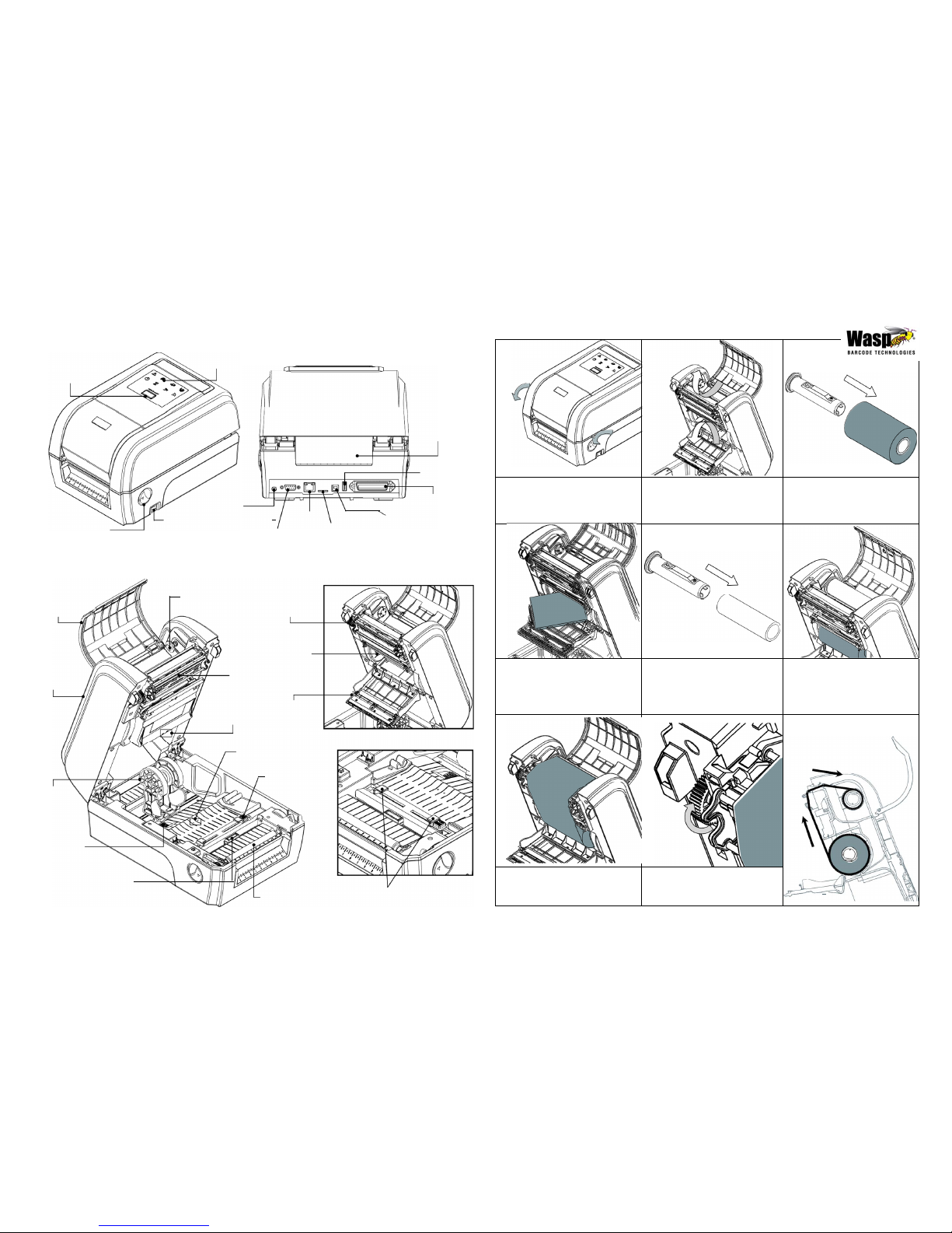
Printer Overview
Feed / Pause
button
WPL308 Quick Start Guide
LED indicator
Power jack
socket
Fan-fold paper
entrance chute
USB host
Centronics
interface
Loading the Ribbon
Top cover
Power
RS-232C
Ethernet
Micro SD
USB
open lever
switch
interface
interface
card socket
interface
Note: The interface picture here is for reference only. Please refer to the product specification for the interfaces
availability.
Ribbon access
cover
Ribbon
rewind hub
Ribbon
rewind gear
Top cover
Ribbon
supply hub
Print head
Gap sensor
(receiver)
Media cover
Gap sensor
(transmitter)
Media holder
Media holder
locking switch
Media guide
adjustment button
Black mark
sensor
Platen roller
Media guides
Page 1 of 2
(1) Open the printer’s top cover by
pulling the top cover open levers
located on each side of the printer
and lifting the top cover to the
maximum open angle.
(2) Open the ribbon access cover and
the media cover.
(3) Insert the ribbon spindle into the
ribbon core.
(4) Install the ribbon right side onto the
supply hub first then align the
notches on the left side and mount
onto the spokes.
Note: The yellow part of spindle is in
left side.
(5) Insert the rewind spindle into the
paper core.
(6) Install the paper core right side
onto the rewind hub first then
align the notches on the left side
and mount onto the spokes.
Note: The yellow part of spindle is
in left side.
* Loading Path for Ribbon
(7) Stick the ribbon onto the ribbon
rewind paper core.
(8) Turn the ribbon rewind gear until
the ribbon plastic leader is
thoroughly wound. Close the ribbon
access cover and the top cover.
Loading the Media
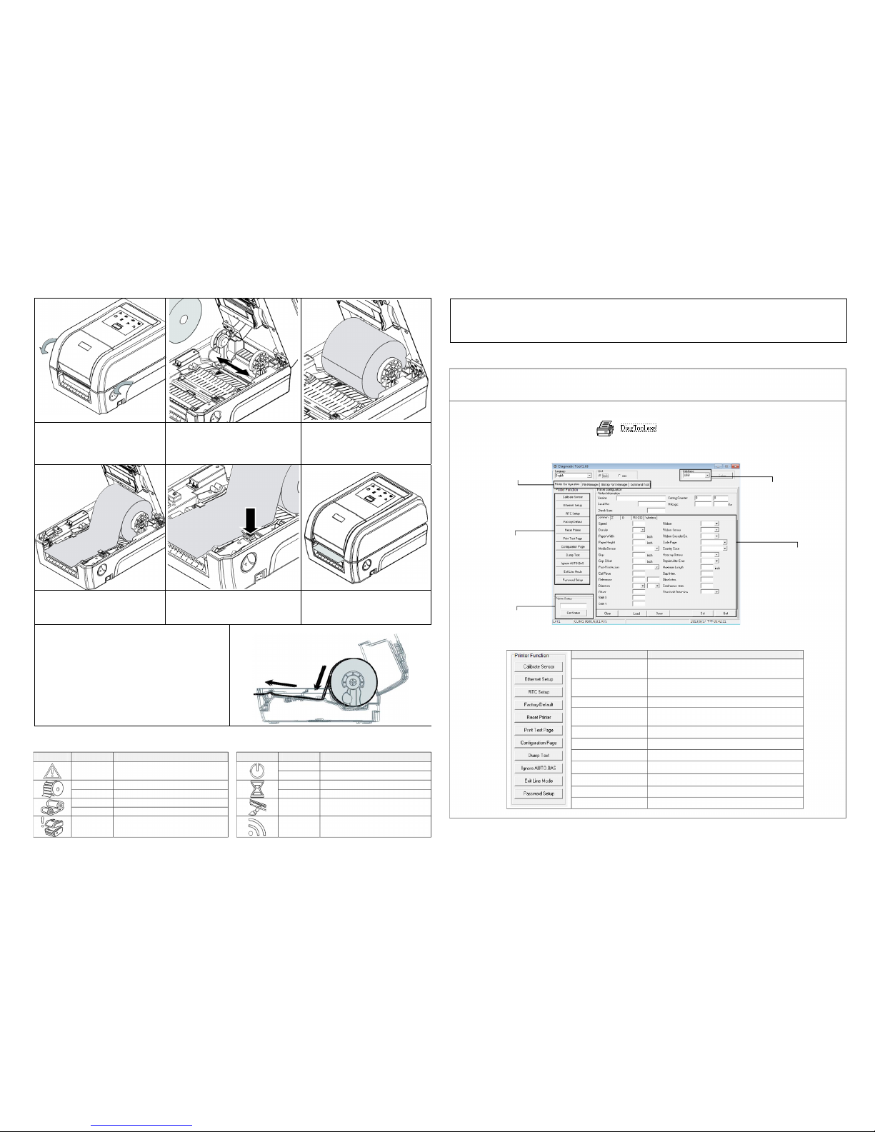
Button Functions
Diagnostic Tool
The Diagnostic Utility is a toolbox that allows users to explore the printer's settings and status; change printer settings;
download graphics, fonts, and firmware; create printer bitmap fonts; and to send additional commands to the printer.
Using this convenient tool, you can explore the printer status and settings and troubleshoot the printer.
Start the Diagnostic Tool:
(1)
Double click on the Diagnostic tool icon to start the software.
(2)
There are four features (Printer Configuration, File Manager, Bitmap Font Manager, Command Tool) included in the
Diagnostic utility.
Features tab
Interface
Printer functions
Printer setup
Printer Status
(3)
The detail functions in the Printer Function Group are listed as below.
Function Description
Calibrate Sensor
Calibrate the sensor specified in the Printer
Setup group media sensor field
Ethernet Setup
Setup the IP address, subnet mask, gateway
for the on board Ethernet
RTC Setup Synchronize printer Real Time Clock with PC
Initialize the printer and restore the settings
Factory Default
to factory default
LED Indicators
LED Status Indication LED Status Indication
On Other errors
On Printer is ready
Blinking Pause
On Out of paper On Erasing memory
Blinking Paper jam Blinking Downloading file
On Out of ribbon
Blinking Need to clear print head
Blinking Ribbon near end
On Print head open Blinking RF communication
Reset Printer Reboot printer
Print Test Page Print a test page
Configuration Page Print printer configuration
Dump Text To activate the printer dump mode
Ignore AUTO.BAS Ignore the downloaded AUTO.BAS program
Exit Line Mode Exit line mode
Password Setup Set the password to protect the settings
*
For more information and features about this printer, please refer to the User’s Manual inside the CD disk.
*
Specifications, accessories, parts and programs are subject to change without notice.
Page 2 of 2
(1)
Feed labels
When the printer is ready, press the button to feed one label to the beginning of next label.
(2)
Pause the printing job
When the printer is printing, press the button to pause a print job. When the printer is paused the power LED will blink
green. Press the button again to continue the printing job.
(1) Open the printer top cover by
pulling the tabs located on each
side towards the front of the printer,
then lift the top cover to the
maximum open angle.
(2) Separate and hold open the media
holders.
(3) Place the roll between the holders
and close them onto the core.
PUSH
(4) Place the paper, printing side face
up, through the media sensor and
place the label leading edge onto
the platen roller.
(5) Move the media guides to fit the label
width by pushing the media guide
adjustment button.
(6) Close the top cover gently.
(7) Use “Diagnostic Tool” to set the media sensor type and
calibrate the selected sensor. (Start the “Diagnostic tool”
Select the “Printer Configuration” tab Click the
“Calibrate Sensor” button ) Please refer to the
diagnostic utility quick start guide for more information.
Note:
Please calibrate the gap/black mark sensor when
changing the media.
* Loading Path for Media
 Loading...