

Wasp WPD220VF User Manual

WPD-220 VF Pole Display
User’s Manual

© Copyright Wasp Technologies®2002.
All rights reserved.
Version 1.0
No part of this publication may be reproduced or transmitted in any form or by
any means without the written permission of Wasp Technologies®.The
information contained in this document is subject to change without notice.
Wasp is a trademark of Wasp Technologies®. All other trademarks or registered
trademarks are the property of their respective owners.

Table of Contents
Introduction ..........................................................................................................1
General Specifications..........................................................................................2
Interface Specifications ........................................................................................3
System Command Details ................................................................................4-6
Command........................................................................................................7-20
Character Set ....................................................................................................21
Dimensions ........................................................................................................23
Installation Guide................................................................................................24

1
WPD-220 VF User’s Manual
Introduction
INTRODUCTION
Thank you for choosing the WPD-220VF Pole Display. The WPD-220VF
provides both reliability and performance in a professional looking design.In this
guide, you will find connection and configuration information to help you connect
the display to your computer.
The WPD-220VF pole display uses a vacuum fluorescent display (VFD) tube
presenting bright and easy to read characters. Because of the VFD technology
the display is viewable from a wide angle. Users will appreciate not having to
remain in a fixed viewing position to see the display; they will be free to move
forward in line and still keep the display readable.The WPD-220VF pole display
has 2 pole sections giving you the choice of 4 different display heights. The
display can be rotated up to 270°.The head of the display can be tilted up to
35°.The combination of these features gives you flexibility to tailor the display
position to your unique application.
The WPD-220VF pole display uses an easy to connect RS-232C serial por t
connection with a wide range of available communication speeds from 300 to
38,400bps.

SPECIFICATIONS
ITEM WPD-220VF
Display method Vacuum fluorescent display
Display color Blue green
Number of characters 40 characters(20 columns x 2 lines)
Brightness 700 cd/m2
Character type 96 alphanumeric
13 kinds of international character set
and 1 user-defined set
Character font 5 x 7dot matrix
Character size 3.5mm x 5.0mm
Character pitch 2mm
Power supply 5VDC or 12VDC or 24VDC
Power consumption 5W
MTBF(power on time) 25000hours
Dimensions 170(W) x 70(H) x 45(D)mm
Viewing angle ± 30 degrees
Rotation angle Maximum 270 degrees
Weight 0.9Kg
Environmental Operating Temperature 5-45°C
Conditions Humidity Less then 95%
Storage Temperature -5-55°C
Humidity Less then 95%
Safety FCC class B CE
2
WPD-220 VF User’s Manual
Specifications
Serial port (RS232C)
Serial port (RS232C) communication
(a) This interface specification is based on EIA RS232C baud rate 300 to 38400
BPS, 8 data bits, none parity, 1 or more stop bits
(b) Serial port (RS232C) communication data link
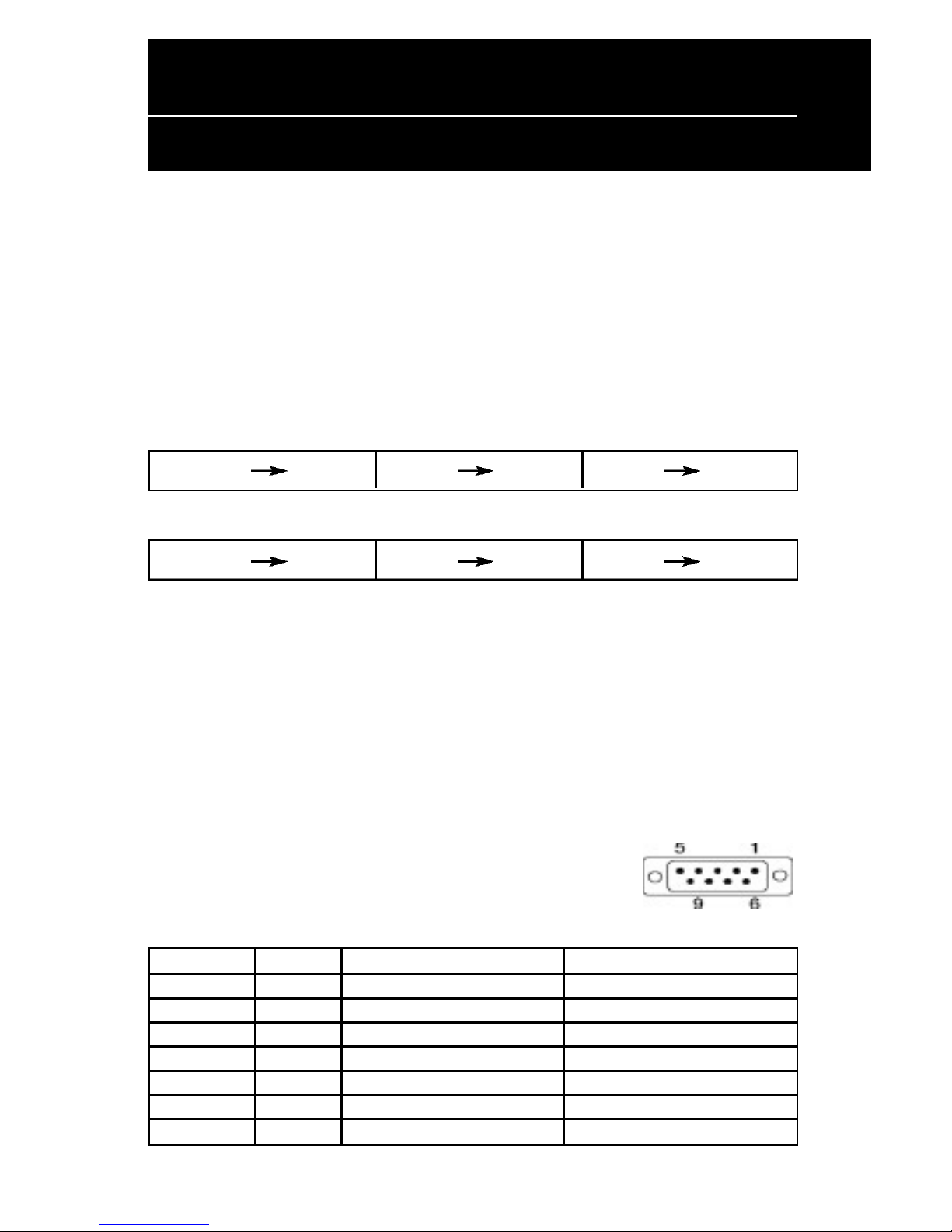
Data link flow chart:
PC/HOST display display printer printer PC/HOST
Control for RTS and DTR :
PC/HOST display display printer printer PC/HOST
(c) The device will activate DTR or RTS signal to PC/host in the following two
conditions:
1. Printer will activate DTR or RTS signal.
2.The pass through buffer is full ( 200 bytes ) .
* If PC/host keeps transmitting the data to printer when CD3220 activate
DTR or RTS, the data will be lost.
Serial port interface to the space-saving base portion
(c) RS232C interface to PC/HOST cable, PC/HOST side
connector pin assignment
Connector type: D-sub 9 pin (Male)
Pin No. Signal Direction Function description
2 TXD From printer to PC/Host Printer status data
3 RXD Input Receive data
4 DSR From PC/HOST to printer Host ready signal
5 GND Signal ground
6 DTR Output Display/printer ready signal
7 RTS Output Display/printer ready signal
8 CTS From PC/HOST to printer Host ready signal
3
WPD-220 VF User’s Manual
Interface Specifications

4
WPD-220 VF User’s Manual
System Command Details
Baud rate
STX 05 B n ETX /Set baud rate and keep it with EEPROM/
ASCII Format STX 05 B n ETX
Dec. Format [02][05][66] n [03]
Hex.Format [02h][05h] [42h] n [03h] 30h<n<37h
Description Change the display communication baud rate.The
baud rate setting can be selected from 300 to 38400.
The setting function will be saved to EEPROM.
N Baud rate
30h 9600
31h 4800
32h 2400
33h 1200
34h 600
35h 300
36h 38400
37h 19200
Reset EEPROM
STX 05 07 n ETX Reset EEPROM
ASCII Format STX 05 07 n ETX
Dec. Format [02][05][07][n][03]
Hex. Format [02h][05h][07h][n][03h]
Description This command will reset the content of EEPROM
(eg. demo scroll data, user-define character, baud
rate setting.)
n=31h clear all EEPROM contents
n=32h clear upper line data message
n=33h clear lower line data message

5
Loading the Ribbon
WPD-220 VF User’s Manual
System Command Details
Save data for demo display
STX 05 L n m ETX Save demo message to EEPROM
ASCII Format STX 05 L n m ETX
Dec. Format [02][05][76] n m [03]
Hex. Format [02h][05h][4Ch] n m [03h]
Description Save demo message for upper line and bottom line
n = 31h save data message for upper line
n = 32h save data message for lower line
m = data message; the maximum data
character is under 200
Run Demo message
STX 05 D 08 ETX Run demo message
ASCII Format STX 05 D 08 ETX
Dec. Format [02][05][68][08][03]
Hex. Format [02h][05h][44h][08][03h]
Description Run demo message for the display

6
WPD-220 VF User’s Manual
System Command Details
Set Communication Option
STX 05 P n ETX Set the communication parity
ASCII Format STX 05 P n ETX
Dec. Format [02][05][80] n [03]
Hex. Format 02h][05h][50h] n [03h] 31h<n<36h
Description Change the display communication parity.
Set 7 or 8 data bit and the parity set for
even, odd, or non-parity.
n Parity
31h N-8-1
32h N-7-1
33h E-8-1
34h E-7-1
35h O-8-1
36h O-7-1
 Loading...