

Page 1
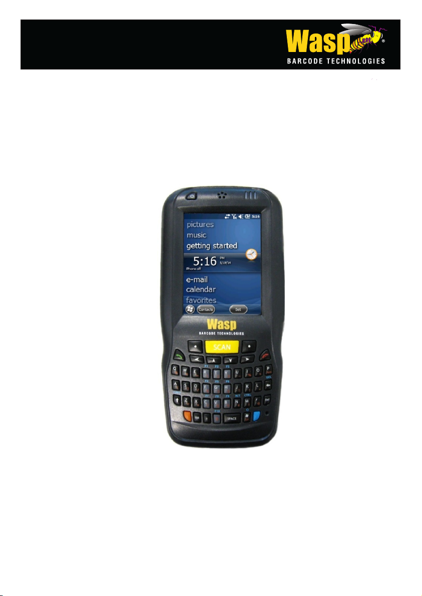
WDT60™
Personal Digital Assistant (PDA)
User’s Manual
Page 2

Wasp Barcode Technologies
1400 10th Street
Plano, TX 75074
Telephone: 866-547-9277
Fax: 214-547-4101
©2013-2014 Wasp Barcode Technologies
An Unpublished Work - All rights reserved. No part of the contents of this documentation or
the procedures described therein may be reproduced or transmitted in any form or by any
means without prior written permission of Wasp Barcode Technologies or its subsidiaries or
affiliates ("Wasp”). Owners of Wasp products are hereby granted a non-exclusive, revocable
license to reproduce and transmit this documentation for the purchaser's own internal
business purposes. Purchaser shall not remove or alter any proprietary notices, including
copyright notices, contained in this documentation and shall ensure that all notices appear
on any reproductions of the documentation. Should future revisions of this manual be
published, you can acquire printed versions by contacting your Wasp representative.
Electronic versions may either be downloadable from the Wasp Barcode Technologies
website (www.waspbarcode.com) or provided on appropriate media. If you visit our website
and would like to make comments or suggestions about this or other Wasp publications,
please let us know via the "Contact " page.
Disclaimer
Wasp Barcode Technologies (“Wasp”) reserves all rights with respect to its trademarks,
service marks, logos, and other indicia ("Marks"). Any unauthorized use of any Wasp-owned
Mark, or any use of a mark that is confusingly similar to, or likely to cause confusion with, an
Wasp-owned Mark, would constitute infringement of Wasp’s exclusive trademark rights.
Logo of Wasp and Wasp ‘bug’ are registered trademarks.
WDT60 and the WDT60 logo are registered trademarks of Wasp Barcode Technologies. All
other brand and product names mentioned herein are for identification purposes only and
may be trademarks or registered trademarks of their respective owners.
Patents
This product is covered by one or more of the following patents:
Design patents: EP001711946, USD633502, ZL201030189483.7
Utility patents: EP0681257B1.
Page 3

iii
CONTENTS
REFERENCES ............................................................................................. v
Conventions .................................................................................................. v
Reference Documentation ............................................................................ v
Services and Support .................................................................................... v
GENERAL VIEW ......................................................................................... vi
1 INTRODUCTION .......................................................................................... 1
1.1 WDT60 Description ....................................................................................... 1
1.2 Inserting a MicroSD Card .............................................................................. 2
1.2.1 Removing the MicroSD Card ........................................................................ 4
2 BATTERIES AND MAINTENANCE ............................................................. 5
2.1 Charging the Battery Pack ............................................................................ 5
2.2 Replacing the Battery Pack ........................................................................... 8
2.3 Cleaning the PDA ....................................................................................... 11
3 CONNECTIONS ......................................................................................... 12
3.1 USB Connection ......................................................................................... 12
3.2 Connection to USB peripherals ................................................................... 14
3.3 RS232 Connection ...................................................................................... 17
3.4 WLAN Connection ...................................................................................... 19
3.5 WPAN Connections .................................................................................... 21
3.6 Wireless and Radio Frequencies Warnings ................................................ 23
4 USE AND FUNCTIONING .......................................................................... 25
4.1 Startup ........................................................................................................ 25
4.1.1 Using the Stylus .......................................................................................... 26
4.2 Windows Embedded Handheld Welcome Wizard ....................................... 27
4.3 Data Capture ............................................................................................... 28
4.3.1 Laser Data Capture ..................................................................................... 29
4.4 Description of the Keys ............................................................................... 30
4.4.1 Alphanumeric Keyboard .............................................................................. 30
4.4.2 Numeric Keyboard ...................................................................................... 31
4.4.3 Resetting the WDT60 .................................................................................. 33
4.5 Status Indicators ......................................................................................... 35
4.5.1 LED Status .................................................................................................. 35
4.5.2 Taskbar ....................................................................................................... 36
4.6 Settings ....................................................................................................... 37
4.6.1 Data Capture Configuration ........................................................................ 38
Decoding Configuration Pages ................................................................... 38
4.6.2 Buttons ........................................................................................................ 46
4.6.3 Quick Buttons .............................................................................................. 47
4.6.4 Triggers ....................................................................................................... 49
Page 4

iv
4.6.5 Application Switcher .................................................................................... 50
4.6.6 Wireless Communications ........................................................................... 51
4.6.7 Stylus Calibration ........................................................................................ 56
4.6.8 Audio Settings ............................................................................................. 58
4.7 Connecting to Other Computers ................................................................. 61
4.7.1 Windows Mobile® Device Center ................................................................ 61
4.7.2 Bluetooth® Manager Device Setup ............................................................. 62
4.8 WASP Desktop Utility.................................................................................. 70
4.8.1 Administrative Options (Admin tab) ............................................................. 71
4.8.2 Locked Web Browser Options (LockedWeb tab) ........................................ 74
4.8.3 Status Icons Options (Status Tab) .............................................................. 79
4.8.4 Windows Controls ....................................................................................... 80
4.8.5 AppSelector Options (AppSelect tab).......................................................... 82
4.9 AppSelector (Application Selector) ............................................................. 86
4.10 Locked Web Browser .................................................................................. 87
4.10.1 Locked Web Browser Special Meta-tags .................................................... 89
4.11 Autostart ...................................................................................................... 93
4.11.1 Installing CAB Files ..................................................................................... 93
4.11.2 How AutoStart Uses Wceload ..................................................................... 94
4.11.3 Interactive CAB Install ................................................................................. 95
4.11.4 Autostart.ini ................................................................................................. 95
5 TECHNICAL FEATURES ......................................................................... 101
5.1 Technical Data .......................................................................................... 101
5.2 Reading Diagrams .................................................................................... 105
6 TEST CODES ........................................................................................... 106
SAFETY REGULATIONS ......................................................................... 110
General Safety Rules ................................................................................ 110
Power Supply ............................................................................................ 110
Laser Safety .............................................................................................. 111
LED Class ................................................................................................. 117
Radio Compliance ..................................................................................... 118
Bluetooth® Approval ................................................................................. 118
FCC Compliance ....................................................................................... 120
RF Exposure Information (SAR) ............................................................... 121
Industry Canada Compliance .................................................................... 122
SAR Compliance ....................................................................................... 123
WEEE Compliance ................................................................................... 124
GLOSSARY .............................................................................................. 126
INDEX ....................................................................................................... 130
Page 5

v
REFERENCES
CONVENTIONS
This manual uses the following conventions:
“User” refers to anyone using an WDT60 PDA.
“PDA” and "WDT60" refer to WDT60 PDA.
“You” refers to the System Administrator or Technical Support person using this
manual to install, configure, operate, maintain or troubleshoot an WDT60 PDA.
“Single Dock” refers to the WDT60 Single Slot Dock.
The label artworks may be only a draft. Refer to the product labels for more precise
information.
REFERENCE DOCUMENTATION
For further information regarding WDT60 refer to the SDK Help on-Line.
SERVICES AND SUPPORT
Wasp provides several services as well as technical support through its website.
Please check our website at: www.waspbarcode.com.
Page 6
vi
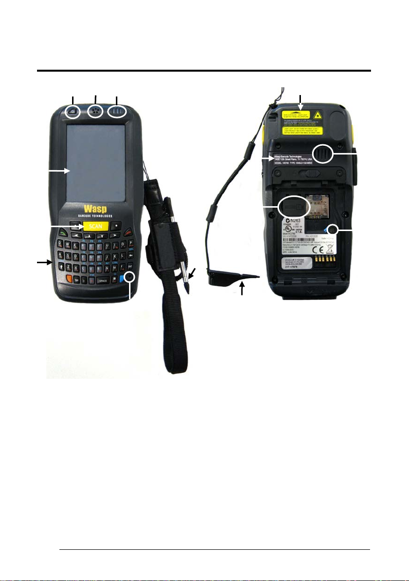
GENERAL VIEW
H
A
E
F
C B D
G
N
I
J
L
K
M
1
A) Color Display
B) ON/OFF Power Key
C) Receiver
D) LEDs
E) Front Scan Key
F) Keyboard
G) Microphone
H) Telescope Stylus (not included in
the box, please order it separately)
I) Laser Safety Label
J) Loudspeaker
K) Product Label
L) MicroSD Card Slot (under battery)
M) Reset Key (under battery)
N) Guitar Pick
Page 7
vii
T
U
O P Q
R
S
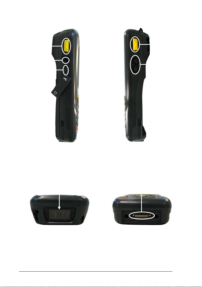
O) Side Scan Key (left)
P) Headset Connector
Q) Micro-USB Port for supplying power
R) Side Scan Key (right)
S) Up/down Volume Keys
and data transfer (host/slave)
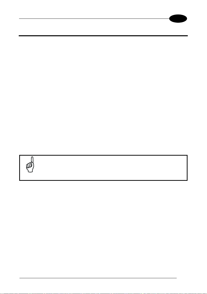
T) Data Capture Window U) Handylink™ Connector (host/slave)
Page 8

This page intentionally left blank
1
Page 9
INTRODUCTION
1
1
1 INTRODUCTION
1.1 WDT60 DESCRIPTION
The WDT60 contains the most innovative technical features, providing them to the
user in an ergonomic and elegant form factor. The accelerometer, the vibrator alert
and the 3 LEDs help to not waste time in the configuration and usage of the product.
Working with the WDT60 becomes an easy pleasure.
Great aesthetics do not put the robustness on a second level. The WDT60 has been
designed for survival in the industrial environmental, outside or inside the four walls.
The reliability of the product continues with the architecture chosen: an 806MHz
processor working with 256 MB of RAM and 512 MB of Flash. A Micro SD card slot
supporting micro SDHC storage cards provides for virtually unlimited storage space.
The WDT60 has been equipped with a 1D laser scanner.
The WDT60 wireless technology provides two radios with internal antennas:
Bluetooth® EDR for fast and close data connections and 802.11 b/g/n Cisco CCX v4
certified Wi-Fi for quick wireless network access.
The WDT60 integrates the latest Windows Embedded Handheld 6.5, tailored for
mobile devices.
Rechargeable battery packs are not initially fully charged. Therefore
the first operation to perform is to charge them. See paragraph 2.1.
NOTE
Page 10
1 WDT60™
2
1
1.2 INSERTING A MICROSD CARD
WDT60 supports microSD memory cards. To access the microSD card slot and
insert the card, proceed as follows:
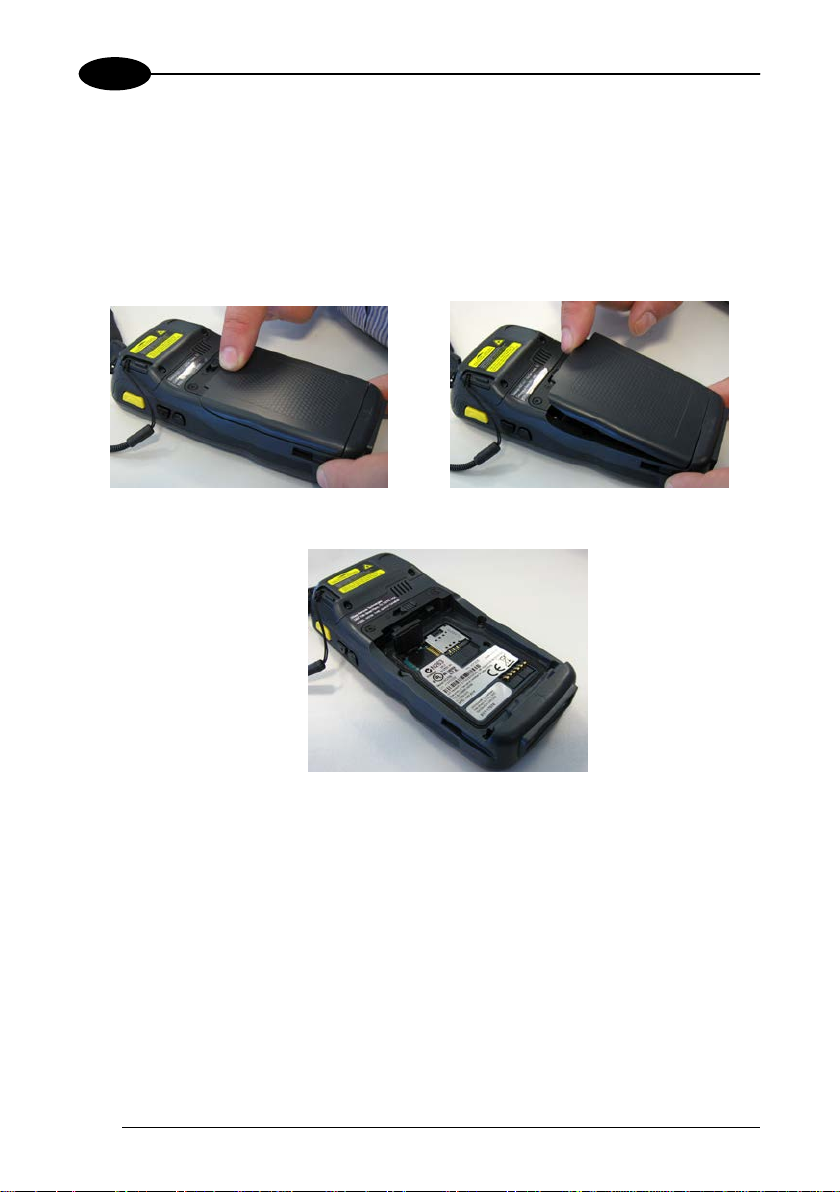
1. Turn off the WDT60.
2. Shift the battery latch to the left and remove the battery pack:
3. Open the card slot and insert the microSD card with the written part downward:
Page 11
INTRODUCTION
3
1
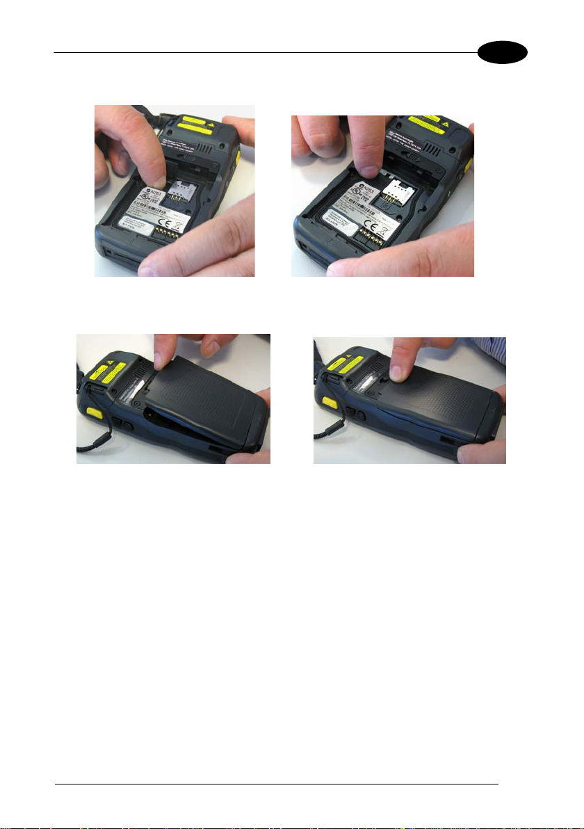
4. Shift the card to the right to lock it into the cardholder; close the card slot:
5. First insert the bottom (contacts) and then the upper side of the battery pack into
the slot. Press until the battery latch clicks.
Page 12

1 WDT60™
4
1
ecautions to avoid damaging the
1.2.1 Removing the MicroSD Card
To remove the microSD card, follow the steps above to access the microSD card
cage under the battery, and remove it from the microSD slot.
Follow proper ESD pr
microprocessors in the WDT60 or the microSD card itself.
CAUTION
Proper ESD precautions include, but are not limited to, working on
an ESD mat and ensuring that the operator is properly grounded.
Do not force the card. If you feel resistance, remove the card, check
the orientation, and reinsert it.
Do not use the microSD card slot for any other accessories.
Page 13
BATTERIES AND MAIN TENANCE
5
2
2 BATTERIES AND MAINTENANCE
Rechargeable backup batteries and battery packs are not initially
fully charged. Therefore the initial operation to perform is to charge
NOTE
CAUTION
2.1 CHARGING THE BATTERY PACK
NOTE
The battery icon on the Taskbar indicates when the battery pack is low.
It is possible to recharge the battery pack by connecting the power supply directly to
the WDT60.
Alternatively, it is also possible to recharge the battery pack by using a Single Cradle.
them. See below.
Annual replacement of rechargeable battery pack avoids possible
risks or abnormalities and ensures maximum performance.
The battery pack autonomy varies according to many factors, such
as the frequency of barcode scanning, RF usage, battery life,
storage, environmental conditi ons, etc.
Page 14
1 WDT60™
6
2
Moreover recharging is possible by USB direct connection with the host computer,
but with longer charging times.
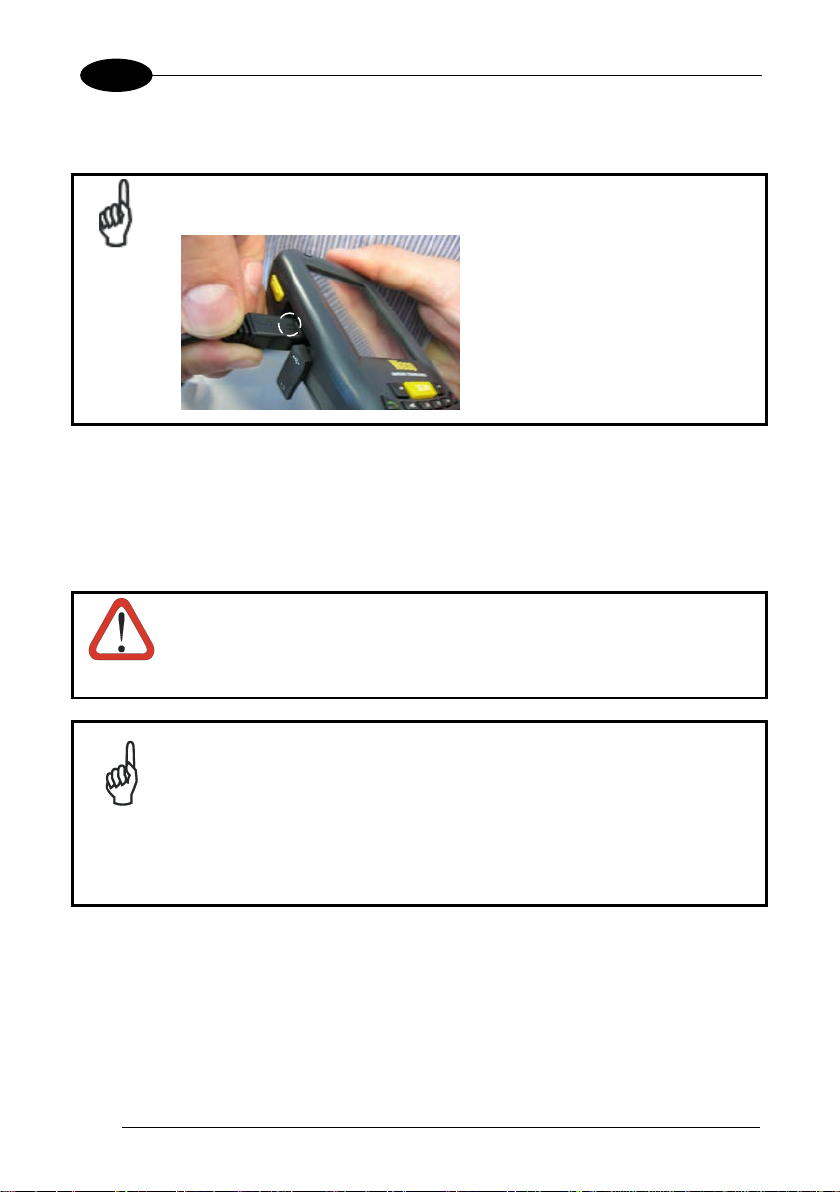
Insert the micro-USB cable output plug into the micro-USB connector
of the WDT60, making sure that the arrow on the plug faces upwards:
NOTE
During the charging process the LED positioned at the right side of the display glows
red constantly. Once the charging process has been completed this LED glows green
constantly.
If the battery pack is removed from the PDA, it can be recharged by inserting it into
the rear slot of a Single Cradle.
Do not use the WDT60 until standard batteries are charged for
minimum 4 hours and extended batteries are charged for minimum 6
CAUTION
hours.
Even if the storage temperature range is wider, in order to achieve
the longest battery life, store the terminal and the spare batteries
between 20 to 30 ºC (68 to 86 ºF).
NOTE
In order to achieve the maximum charging rate the WDT60 should be
charged beetween 0-40 °C.
Never charge the main device or spare batteries in a closed space
where excessive heat can build up.
Page 15
BATTERIES AND MAIN TENANCE
7
2
The battery level may not be displayed correctly for some minutes
after the disconnection if the WDT60 is disconnected from power
before the charging cycle is completed.
NOTE
supply
The WDT60 may get warm during charging; this is normal and does
not mean a malfunction.
NOTE
Use only a USB-IF compliant USB port as a charging source.
NOTE
Page 16
8
2
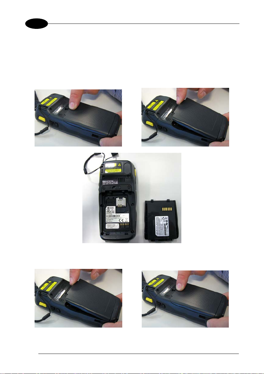
2.2 REPLACING THE BATTERY PACK
To correctly replace the battery pack, proceed as follows.
1. Turn off the WDT60.
2. Shift the battery latch to the left and remove the battery pack:
1 WDT60™
3. Install the new battery pack, first insert the bottom (contacts) and then the upper
side of the battery pack into the slot. Press until the battery latch clicks.
Page 17

BATTERIES AND MAIN TENANCE
9
2
Installing, charging and/or any other action should be done by
authorized personnel and following this manual.
WARNING
The battery pack may get hot, explode, ignite, and/or cause serious
injury if exposed to abusive conditions.
If the battery pack is replaced with an improper type, there is risk of
explosion and/or fire.
Do not place the battery pack in or near a fire or other heat source;
do not place the battery pack in direct sunlight, or use or store the
battery pack inside unventilated areas in hot weather; do not place
the battery pack in microwave ovens, in clothes dryers, in high
pressure containers, on induction cook surfaces or similar devices.
Doing so may cause the battery pack to generate heat, explode or
ignite. Using the battery pack in this manner may also result in a loss
of performance and a shortened life expectancy.
Use only a Wasp approved power supply. The use of an alternative
power supply will void the product warranty, may cause product
damage and may cause heat, an explosion, or fire.
The area in which the units are charged should be clear of debris
and combustible materials or chemica ls.
Do not use the battery pack of this terminal to power devices other
than this PDA.
Immediately discontinue use of the battery pack if, while using,
charging or storing the battery pack, the battery pack emits an
unusual smell, feels hot, changes colour or shape, or appears
abnormal in any other way.
Do not short-circuit the battery pack contacts connecting the positive
terminal and negative terminal. This might happen, for example,
when you carry a spare battery pack in your pocket or purse;
accidental short–circuiting can occur when a metallic object such as
a coin, clip, or pen causes direct connection of the contacts of the
battery pack (these look like metal strips on the battery pack). Short–
circuiting the terminals may damage the battery pack or the
connecting object.
Do not apply voltages to the batter y pack contact s.
Do not pierce the battery pack with nails, strike it with a hammer,
step on it or otherwise subject it to strong impacts, pressures, or
shocks.
Page 18
10
2
WARNING
Do not disassemble or modify (i.e. bend, crush or deform) the battery
pack. The battery pack contains safety and protection devices,
which, if damaged, may cause the battery pack to generate heat,
explode or ignite.
In case of leakage of liquid from the battery, avoid contact with liquid
the skin or eyes. If the contact occurs, immediately wash the affected
area with water and consult a doctor.
Do not solder directly onto the battery pack.
Do not expose the battery pack to liquids.
Avoid any knocks or excessive vibrations. If the device or the battery
is dropped, especially on a hard surface, you should take it to the
nearest Authorised Repair Centre for inspection before continuing to
use it.
Do not replace the battery pack when the device is turned on.
Do not remove or damage the battery pack’s label.
Do not use the battery pack if it is damaged in any part.
Battery pack usage by children should be supervised.
Collect and recycle waste batteries separately from the device in
compliance with European Directive 2006/66/EC, 2011/65,
2002/96/EC and subsequent modifications, with US and China
regulatory laws and regulations about the environment.
1 WDT60™
In order to guarantee an adequate operating autonomy, when
replacing the battery pack the PDA checks the battery energy level.
If the battery is not sufficiently charged, the WDT60 does not turn on
(when pressing the ON/OFF key).
NOTE
In this case, either substitute the battery pack with a charged one
(sufficiently charged) or insert the WDT60 into a powered cradle or
plug it into the direct power supply.
To maximize battery life, turn off radios when they are not needed.
NOTE
Page 19

BATTERIES AND MAIN TENANCE
11
2
2.3 CLEANING THE PDA
Periodically clean the WDT60 with a slightly dampened cloth.
Do not use alcohol, corrosive products or solvent s.
Page 20

1 WDT60™
12
3
A B C
3 CONNECTIONS
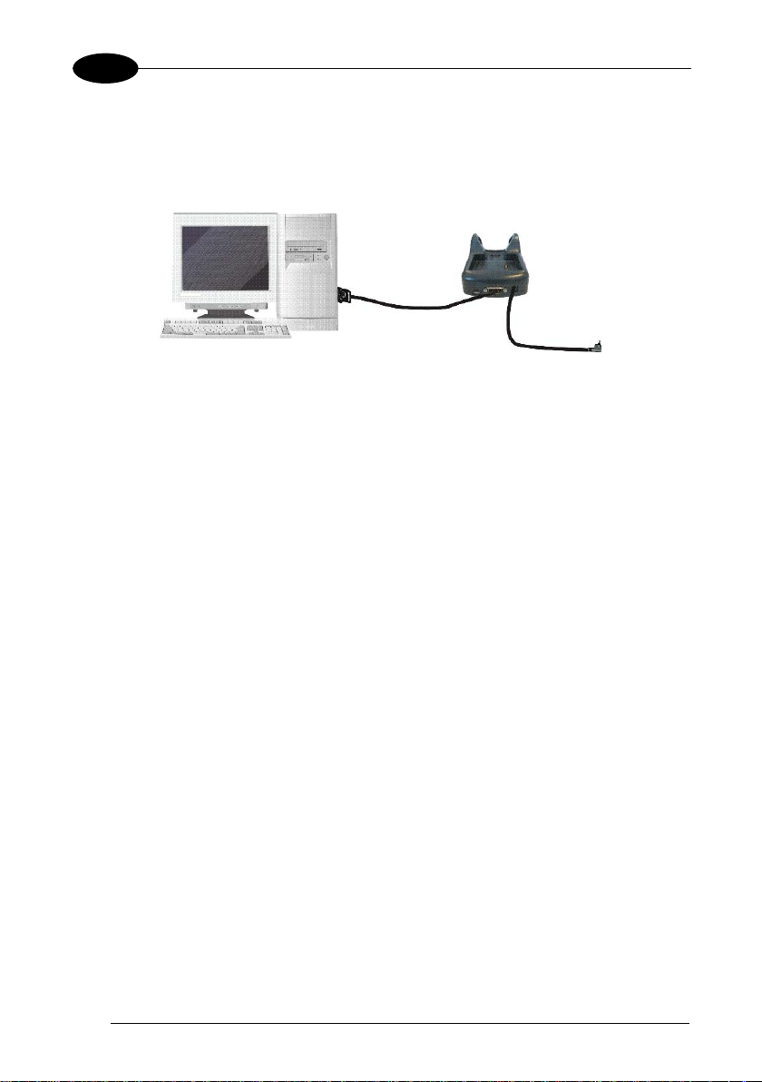
3.1 USB CONNECTION
You can use a standard micro USB cable or a HandyLink™ cable to directly connect
the WDT60 to a host computer to transfer data through the USB interface.
Key:
A Host computer C WDT60
B Standard Micro USB cable/
HandyLink™ USB Client Cable
Connection through the cable complies to the USB 1.1 standard.
NOTE
Insert the micro-USB cable output plug into the micro-USB connector
of the WDT60, making sure that the arrow on the plug faces upwards:
NOTE
Page 21
CONNECTIONS
13
3
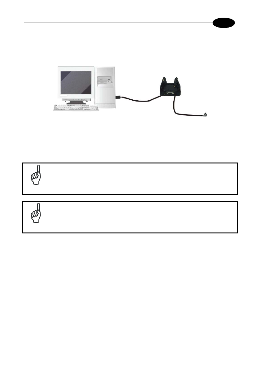
BD C
A
The Single Dock can be connected to the Host by means of a Micro-B US B cord.
Once the host computer has been turned on, insert the WDT60 PDA into the cradle.
Key:
A Host computer C WDT60 Single Slot Dock
B Micro USB Client Cable D Power Adapter
Connection through the cradle complies to USB 1.1 standard.
NOTE
The actual data transfer speed can be appreciably lower than the
maximum theoretical speed.
NOTE
Page 22
1 WDT60™
14
3
A B C D A B C
D
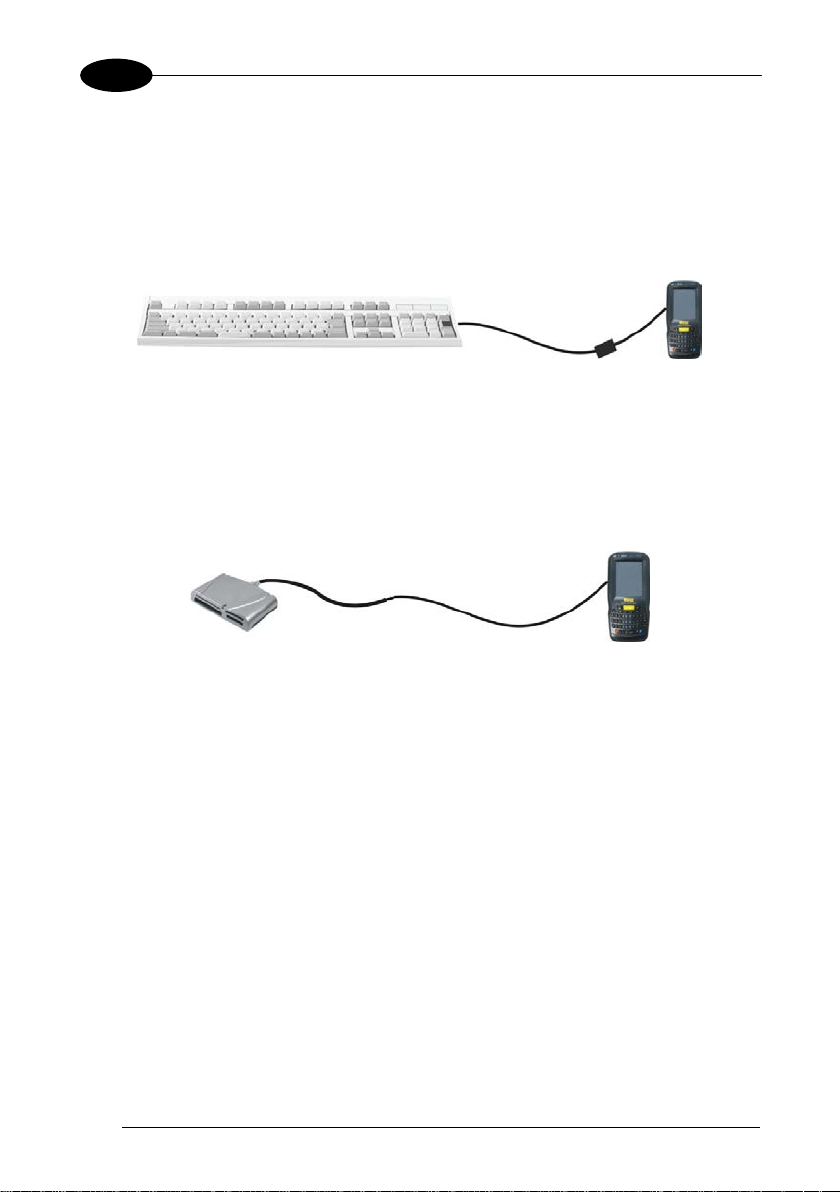
3.2 CONNECTION TO USB PERIPHERALS
To connect the WDT60 to a USB keyboard or a memory device, connect the terminal
to a micro USB host cable or to a HandyLink™ micro USB host cable (together with a
standard A to micro A USB cable).
For all these devices max imu m current dr aw must be less than 100mA.
Key:
A Keyboard with USB interface C Micro USB Host Cable/ HandyLink™
Micro USB Host Cable
B WDT60 D Standard A to Micro A USB Cable
Key:
A USB hard drive/ external
memory source
C Micro USB Host Cable/ HandyLink™
Micro USB Host Cable
B WDT60 D Standard A to Micro A USB Cable
Page 23
CONNECTIONS
15
3
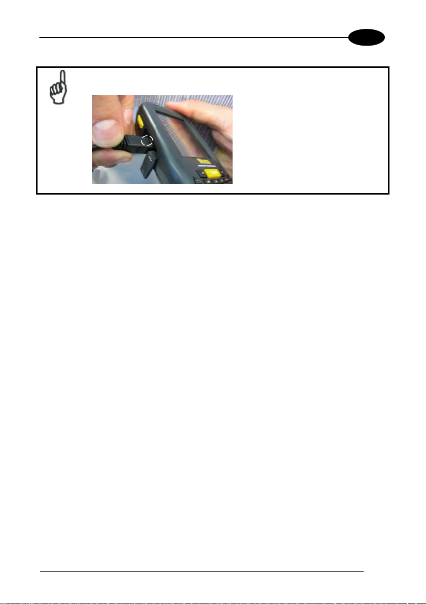
Insert the micro-USB cable output plug into the micro-USB connector
of the WDT60, making sure that the arrow on the plug faces upwards:
NOTE
Page 24
1 WDT60™
16
3
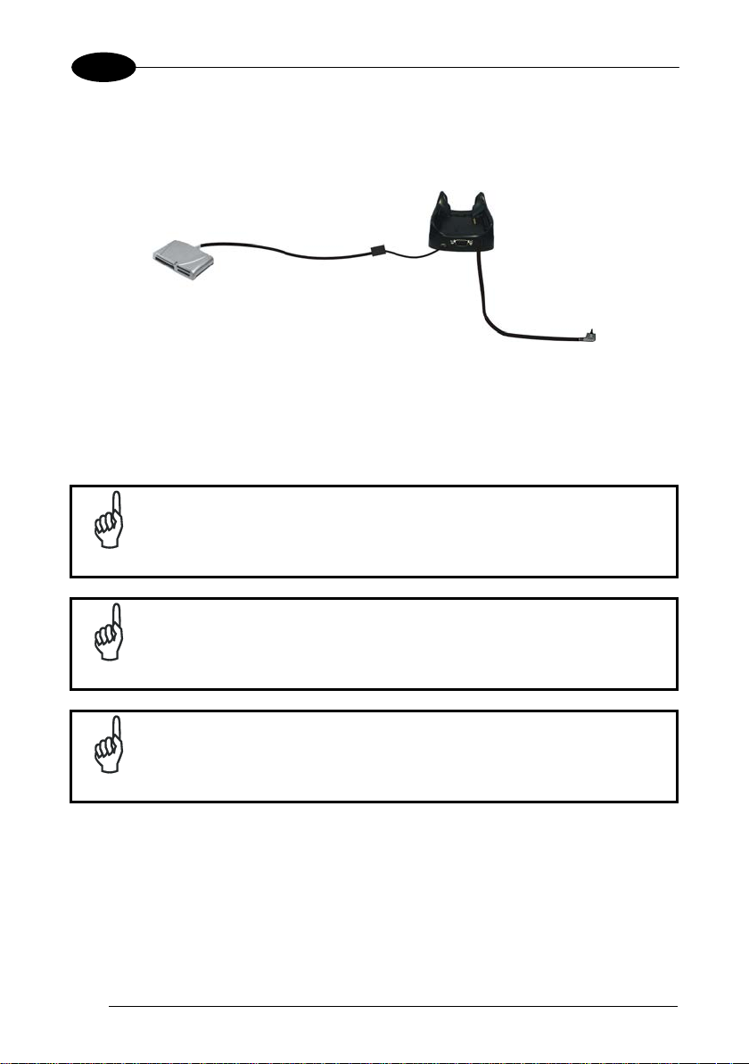
B D C A E
Connect the Single Slot Dock to the peripheral by means of a Micro-A USB cord, or
use a Micro-A to Std-A receptacle USB adapter (together with a standard USB cable
if needed).
A USB Peripheral (memory) D Standard A to Micro A USB Cable
B WDT60 Single Slot Dock E Power Adapter
C Micro USB Host Cable
WDT60 works with most of the mentioned USB peripherals. Wasp
cannot guarantee the interoperability of WDT60 with all devices on
NOTE
the market.
Connection is compliant to USB 1.1 standard.
NOTE
The actual data transfer speed can be appreciably lower than the
maximum theoretical speed.
NOTE
Page 25
CONNECTIONS
17
3
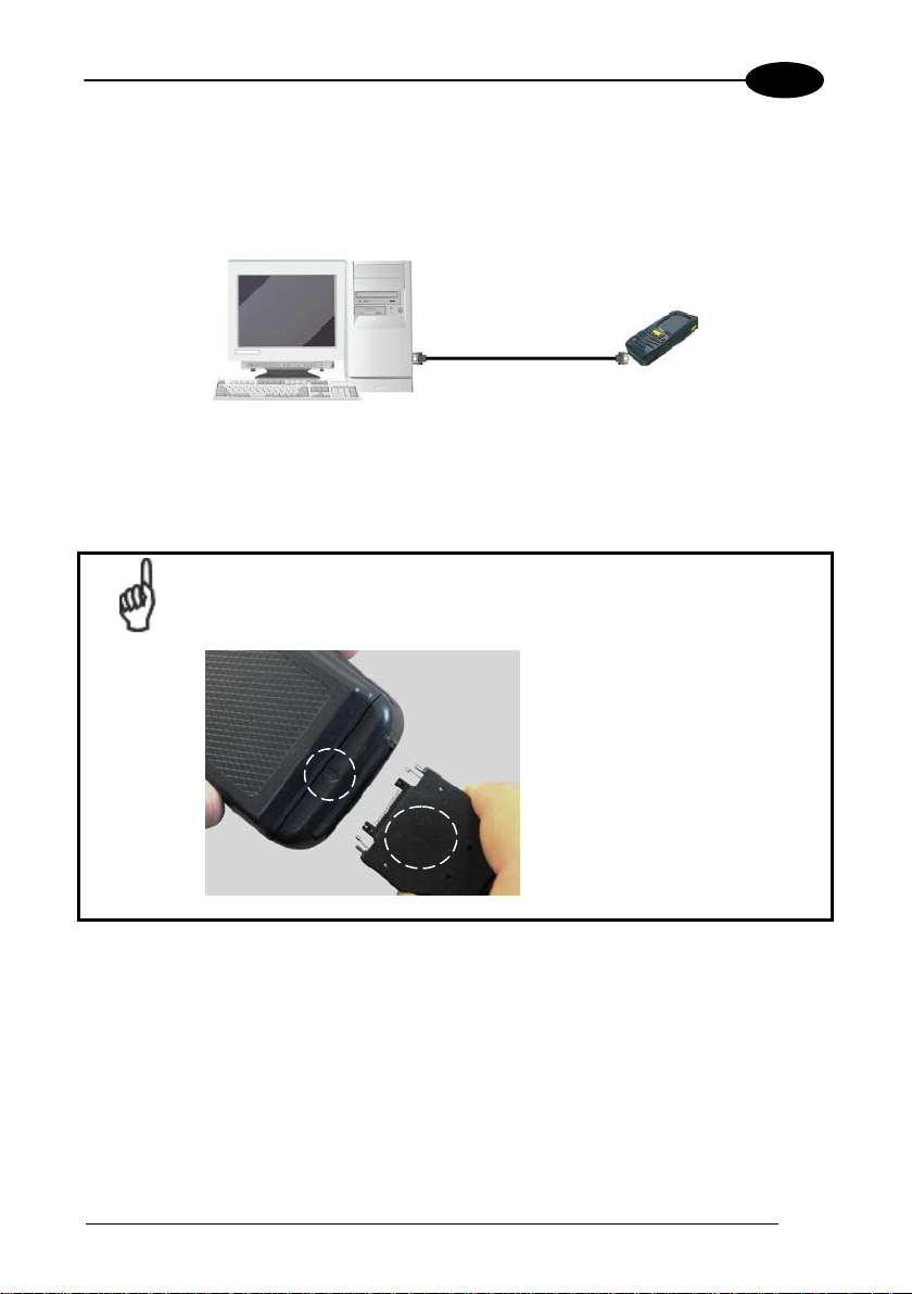
A B C
3.3 RS232 CONNECTION
You can use a HandyLink™ micro RS232 client cable to directly connect the WDT60
to a host computer to transfer data through the RS232 interface
Key:
A Host computer C WDT60
B HandyLink™ Micro RS232
Client Cable
Insert the HandyLink™ cable output plug into the HandyLink™
connector of the WDT60, making sure that both the arrows on the
connector and the WDT60 face upwards:
NOTE
Page 26
1 WDT60™
18
3
A B C
D
The Single Slot Dock can be connected to the Host by means of a standard null
modem cable.
Once the Host computer has b een turned on, in sert the WDT60 PDA into the cradle.
Key:
A Host Computer C WDT60 Single Slot Dock
B RS232 Null Modem Cable D Power Adapter
Page 27
CONNECTIONS
19
3
A B C
A
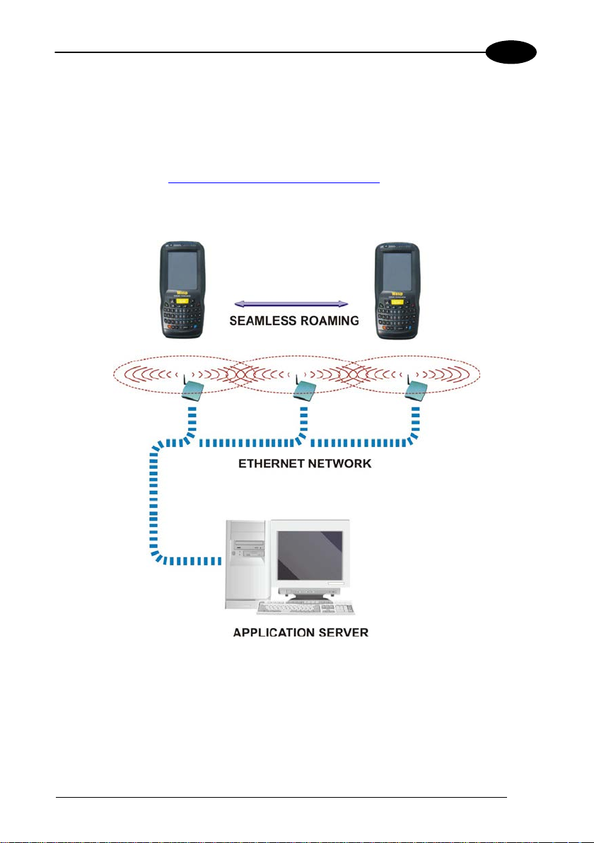
3.4 WLAN CONNECTION
WDT60 802.11 b/g/n radio models can communicate with the host using the onboard Wi-Fi radio and an Access Point connected to the host computer network.
For models using the 802.11 b /g/n radio, you can find information about the applet for
radio configuration: http://www.summitdata.com/SCU.htm.
To launch this utility you can tap the specific icon if it is visible on the taskbar or you
can select the menu item: Start > Summit and tap the ‘SCU’ icon.
Key:
A) WDT60
B) Access poin t
C) Host – Application Server
Page 28
20
3
Area coverage and radio performance may vary, due to
NOTE
NOTE
NOTE
NOTE
1 WDT60™
802.11 b/g/n radio module is on by default, in order to avoid wasting
energy, you can switch it off using SCU.
Suspending the terminal powers off the 802.11 b/g/n radio and drops
the radio connection. When the terminal resumes, depending on the
radio power mode and security protocol selected, it may take up to
30 seconds for the 802.11 b/g/n radio driver to re-associate the radio
to the network.
environmental conditions, access point types or interference caused
by other devices (microwave ovens, radio transmitters, etc.).
In case of heavy usage the WDT60 may get warm; this is normal and
does not mean a malfunction.
Page 29
CONNECTIONS
21
3
NOTE
A
B
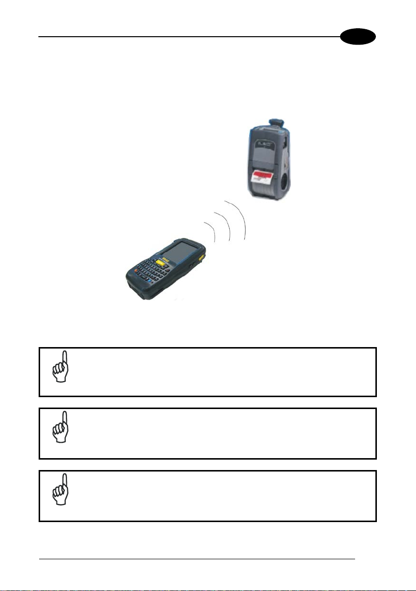
3.5 WPAN CONNECTIONS
WDT60 Bluetooth® models can communicate with a Bluetooth® device, such as a
printer, within a range of 10 m, using the on-board Bluetooth® module.
Key:
A) WDT60
B) Bluetooth® printer
In order to extend battery life, the Bluetooth® module is off by
default. If you need to have Bluetooth® working, the module must be
powered on using the Wireless Communications applet (see par.
4.6.6), and perform the Discovery procedure (see par. 4.7.2).
Suspending the terminal powers off the Bluetooth® radio and drops
the piconet (Bluetooth® connection). When the terminal resumes, it
takes approximately 10 seconds for the Bluetooth® radio driver to re-
NOTE
initialize the radio.
Area coverage and Bluetooth® radio performance may vary, due to
environmental conditions or interference caused by other devices
NOTE
(microwave ovens, radio transmitters, etc.).
Page 30
22
3
1 WDT60™
Calls can be made or received using the WDT60 as a phone
handset, using the WDT60 headset or using a Bluetooth® headset.
NOTE
During a call, you can set the speaker volume by pressing the
volume keys on the side of the WDT60.
NOTE
In case of heavy usage the WDT60 may get warm; this is normal and
does not mean a malfunction.
NOTE
Page 31

CONNECTIONS
23
3
Unauthorized antennas, modifications or attachments could
recommends persons with
pacemakers or other medical devices to follow the same
endations provided by Health Industry Manufacturers
3.6 WIRELESS AND RADIO FREQUENCIES WARNINGS
Use only the supplied or an approved replacement antenna.
damage the product and may violate laws and regulations. The
antennas inside the WDT60 are not user-accessible and cannot be
WARNING
WARNING
WARNING
replaced by end users. Send any faulty equipment to Wasp
Barcode Technologies for repair.
Most modern electronic equipment is shielded from RF signals.
However, certain electronic equipment may not be shielded against
the RF signals generated by WDT60.
Wasp Barcode Technologies
recomm
Associations for mobile phones.
Persons with pacemakers:
• Should ALWAYS keep this device more than twenty five (25) cm
from their pacemaker and/or any other medical device;
• Should not carry this device in a breast pocket;
• Should keep the device at the opposite side of the pacemaker
and/or any other medical device;
• Should turn this device OFF or move it immediately AWAY if
there is any reason to suspect that interference is taking place.
• Should ALWAYS read pacemaker or any other medical device
guides or should consult the manufacturer of the medical device
to determine if it is adequately shielded from external RF energy.
In case of doubt concerning the use of wireless devices with an
implanted medical device, contact your doctor.
Turn this device OFF in health care facilities when any regulations
posted in these areas instruct you to do so. Hospitals or health care
facilities may use equipment that could be sensitive to external RF
WARNING
energy.
Page 32

24
3
WARNING
WARNING
WARNING
1 WDT60™
RF signals may affect improperly installed or inadequately shielded
electronic systems in motor vehicles. Check with the manufacturer
or its representative regarding your vehicle. You should also
consult the manufacturer of any equipment that has been added to
your vehicle.
An air bag inflates with great force. DO NOT place objects,
including either installed or portable wireless equipment, in the area
over the air bag or in the air bag deployment area. If a vehicle’s
wireless equipment is improperly installed and the air bag inflates,
serious injury could result.
Turn off the device when in any area with a potentially explosive
atmosphere. Observe restrictions and follow closely any laws,
regulations, warnings and best practices on the use of radio
equipment near fuel storage areas or fuel distribution areas,
chemical plants or where any operation involves use of explosive
materials.
Do not store or carry flammable liquids, explosive gases or
materials with the device or its parts or accessories.
Areas with a potentially explosive atmosphere are often, but not
always, clearly marked or shown.
Sparks in such areas could cause an explosion or fire, resulting in
injury or even death.
Page 33

USE AND FUNCTIONING
25
4
Today Screen
Start Menu
4 USE AND FUNCTIONING
The use of the WDT60 depends on the application software loaded. However there
are several parameters that can be set and utilities that can be used to perform some
basic functions such as data capture, communications, file management, etc
4.1 STARTUP
The WDT60 turns on when the battery pack or the external supply is inserted and the
ON/OFF Power button is pressed.
After the battery pack is installed, use the [ON/OFF] key to turn the PDA on and off.
As soon as the PDA is on, the Windows Embedded Handheld 6.5 desktop
configuration will appear on the screen. Wait a few seconds before starting any
activity so that the PDA completes its startup procedure.
Use the styl us (par. 4.1.1) as suggested to select icons and options.
The PDA goes into power-off (low power with display and keyboard backlight off)
when it is not used for more than a programmable timeout, which is defined in the
POWER applet of the Control Panel. In this mode it can be awakened (resuming
operation) by the [ON/OFF] key.
Page 34

1 WDT60™
26
4
Touch the screen once with the stylus to open items and select
Hold the stylus on the screen and drag across the screen to
Tap and hold the stylus on an item to see a list of actions
up menu that appears, tap the
action you want to perform.
The PDA can also be awakened or turned off by applications.
NOTE
4.1.1 Using the Stylus
The stylus selects items and enters information. The stylus functions like a mouse.
Tap:
Drag:
Tap-and-hold:
options.
select text and images. Drag in a list to select multiple items.
available for that item. On the pop-
To recalibrate the touch screen use the Screen applet (see par. 4.6.7).
Use only original Wasp styluses supplied with the product itself.
In harsh applications, use of screen protectors should be taken into
CAUTION
consideration, in order to extend the touch screen operating life.
To prevent damage to the screen, do not use sharp objects or any
tool other than the Wasp provided stylus.
Do not apply too much pressure when touching the screen.
For applications where an intensive use of the touch screen is
foreseen, please consider that touch screen components are subject
to progressive wear.
Page 35

USE AND FUNCTIONING
27
4
4.2 WINDOWS EMBEDDED HANDHELD WELCOME W IZARD
In W indows Embedded Handheld, at the very first WDT60 startup, following a clean
boot or following a Registry restore to default values, the PDA startup (see par. 4.1)
is preceded by the Welcome Wizard.
Welcome Wizard Screen
The Welcome Wizard allows the user to calibrate the touch screen (see par. 4.6.7).
Touch Screen Calibration Screen
Page 36

28
4
4.3 DATA CAPTURE
To capture data first of all tap Start > Settings > System > Decoding:
1 WDT60™
To configure and enable data capture parameters refer to par. 4.6.1.
Page 37

USE AND FUNCTIONING
29
4
4.3.1 Laser Data Capture
To scan barcodes, point the WDT60 laser model onto the code from a distance within
the reading range while pressing the SCAN key.
The lighted band emitted by the laser must completely cross the barcode as shown in
the figure below.
If the scan has taken place correctly:
− the Good Read LED glows steadily Green for a configurable time;
− if enabled, the Good Read Beep plays.
Remove the protective film cover over the Laser Output Window
before use, if present.
NOTE
Page 38

1 WDT60™
30
4
4.4 DESCRIPTION OF THE KEYS
The WDT60 comes with two different keyboards, an alphanumeric keyboard
(QWERTY), having 46 keys, and a numeric keyboard, having a total of 27 keys.
4.4.1 Alphanumeric Keyboard
Page 39

USE AND FUNCTIONING
31
4
4.4.2 Numeric Keyboard
Page 40

32
4
Main Keys Function
lets you move forwards,
backwards, upwards or downwards within text fields,
ore a
standard key, it enables the character or function printed
Blue modifier (one shot key): when pressed before a
standard key, it enables the character or function printed
or OFF. It is placed on the
In blue mode, the Telephone End key generates a
(e.g. touch screen calibration
application).
KEY FUNCTION
1 WDT60™
Pressing the SCAN key starts barcode data capt ure.
Pressing cursor keys
scroll through a Menu list or browse among folder files.
Orange modifier (toggle key): when pressed bef
in yellow above the key.
in blue above the key
It powers the WDT60 ON
upper left side of the terminal.
VK_ESCAPE virtual key code for applications that use
the Esc key to cancel
Page 41

USE AND FUNCTIONING
33
4
4.4.3 Resetting the WDT60
There are several reset methods for the WDT60.
A warm boot terminates an unresponsive application and clears the working RAM,
but preserves the file system. Registry is restored from persistent memory if available
or returned to factory default.
A cold boot forces all applications to close, completely reinitializing the system. It
clears the working RAM, but the file system is preserved. Registry is restored from
persistent memory.
A clean boot restores the WDT60 to a clean configuration: both the Registry and the
file
system return to a clean status that conforms to factory default.
Warm Boot
To perform a warm boot, press and hold the following keys:
Cold Boot
To perform a cold boot, do the following steps:
1. Turn off the WDT60 by pressing the on-off key.
2. Slide the battery latch leftward and remove the battery pack.
3. Press the reset button.
4. Insert the battery pack.
5. Turn on the WDT60 by pressing the on-off key.
Page 42

1 WDT60™
34
4
Warm Boot
Cold Boot
Clean Boot
Registry
Restored from
flash
Restored from
flash
Clean configuration (no user
config)
File
System
Clean Boot
To perform a clean boot, do the following steps:
1. Perform a Warm Boot (see Warm Boot)
2. Before the splash screen appears, press and hold down the 0 and Telephone
End keys sim ultaneousl y:
A dialog box will appear asking for confirmation. Press the Enter Key to confirm. If
you wish to cancel the clean boot, press Esc by pressing Blue + Telephone End.
Preserved Preserved Clean Installation (no user files)
Page 43

USE AND FUNCTIONING
35
4
buttons until the bar code is decoded.
decode.
(left side)
switch to glow red and continue charging
normally.
(center)
4.5 STATUS INDICATORS
4.5.1 LED Status
The WDT60 provides three different LEDs signaling the PDA status.
LED STATUS
Good Read
(right side)
Green
Charging Status
Red It is constant while charging.
Red
Green
Red blinking
Amber
Scanning LED is ON from the time the
user hits the scan button or side trigger
Scanning LED is ON, showing a good
It is constant once the charging process
has been completed (full charge).
In case of charge fault it is constant for
two hours, then it starts blinking.
It is constant when charging a severely
discharged main battery until the battery
has sufficient charge for its controller to
begin communicating with the WDT60's
power system. Once the battery is
communicating, the charge LED will
Keyboard Status
Yellow solid Yellow alternate key mode.
Off Keyboard in primary.
Blue solid Blue alternate key mode
Sky blue solid CapsLock enabled.
Page 44

1 WDT60™
36
4
Opens the Connections balloon, which includes hypertext links
to the Wireless Manager and the Connections applet. (see par.
Opens the Volume balloon, which allows the user to control the
lumes, and to control
4.5.2 Taskbar
The Taskbar provides information about the time, the battery level, the keyboard
function, and the decoding status.
Windows Embedded Handheld Taskbar
ICONS DESCRIPTION
Zooms the screen.
4.6.6).
Displays the battery status.
main volume, in-call volume, to mute all vo
the vibrator.
Opens Clock & Alarms control panel applet. It allows the user to
set date, time and alarms.
Page 45

USE AND FUNCTIONING
37
4
4.6 SETTINGS
From the Start menu, tap Settings. The settings are organized hierarchically.
Control panel applets are displayed as icons; each icon corresponds to one applet:
Windows Embedded Handheld Control Panel
Page 46

1 WDT60™
38
4
4.6.1 Data Capture Configuration
You can configure the WDT60’s decoding options by tapping Start -> Settings ->
System -> Decoding:
There are two sections in the Decoding control panel, each containing additional
pages. There are seven General Configuration pages and multiple Barcode
symbology pages.
DECODING CONFIGURATION PAGES
Select the desired configuration from the options shown in the figure below, and the
other Decoding Properties figures on the following pages.
Select General or 1D Bar Code, then use the menu or tap the left and right arrow
keys to navigate the different pages of the Decoding utility. The menu options will
change to reflect the items most recently selected.
Page 47

USE AND FUNCTIONING
39
4
Notification
From the Decoding menu, tap Configure > General > Notification. Use it to set
volume, tone, duration, and number of various types of beeps.
Good Read
From the Decoding Properties applet, tap Configure > General > Good Read. Use it
to enable Good Read indications, the use of a vibrator feedback and to set the
decoding timeout for decoding labels.
Page 48

1 WDT60™
40
4
Formatting
From the Decoding Properties page, tap Configure > General > Formatting. Use it to
configure prefix, suffix and data separator character strings.
General Options
From the Decoding menu, tap Configure > General > General Options. Select from
Label Programming Enable, Symbology IDs, Group Separator Replacement,
Remove non-printable characters and Enable curved surfaces.
Page 49

USE AND FUNCTIONING
41
4
Decoding Options
From the Decoding Properties applet, tap Configure > General > Decoding Options.
Use it to configure the User ID for symbologies, Redundancy and Aggressive
Decoding (if supported by the decoding module). Select a symbology to view or
change the available properties settings.
Page 50

1 WDT60™
42
4
Spot Beam
From the Decoding Properties applet, tap Configure > General > Spot Beam. It
allows enabling and configuration of Spot Beam and triggering modes.
It is only available on devices equipped with laser and advanced long range laser
decoding modules that support the Spot Beam Feature.
Page 51

USE AND FUNCTIONING
43
4
Devices
From the Decoding Properties applet, tap Configure > General > Devices. Use it to
enable or disable the keyboard wedge for Barcode scanner. Also use it to enable or
disable the Clipboard mode for passing decoding data to a receiving application.
When the Clipboard checkbox is checked, the Windows clipboard is used to pass
label data, which can be much faster than the keyboard wedge at typing label data
from a large label one character at a time. The disadvantage is that label data will
replace any data already in the WDT60's clipboard.
Page 52

1 WDT60™
44
4
1D Barcode Symbology Pages
Use the drop-down menus from Configure > 1D Barcode, or tap the left and right
arrow keys to navigate the different pages of the barcode symbology pages.
Each barcode symbology opens to its own page, as shown in the figure below. Refer
to the sample symbology control panels for examples of the types of fields and
options you can modify.
Codabar: Select Enable, Min/Max Lengths, Enable Checksum, Send Checksum,
Send Start/Stop and Convert to CLSI.
Page 53

USE AND FUNCTIONING
45
4
Decoding Settings
Select from the Decoding Properties Settings menu to restore previous
configurations and/or other available default settings. Choose from:
• Factory Defaults
• Minimum Settings
• Maximum Settings
• Save (New Settings)
• Revert to Saved Settings
The settings are saved when you tap OK.
The settings are saved when you tap ‘Yes’.
When open, Decoding Properties acts as a simple barcode test tool that provides the
Data decoded and the Data Type of the barcode scanned.
Page 54

1 WDT60™
46
4
4.6.2 Buttons
From the Start menu, tap Settings > Personal > Buttons.
On the Program Buttons tab, customize the program hardware buttons to launch your
most used applications. Under ‘Select a button’, tap the button you want to assign a
program to, and then select a program from ‘Assign a pro gra m’.
To configure the way the up/down control repeats, use the Up/Down Control applet
(Start > Settings > Personal > Buttons and then tap Up/Down Control).
Page 55

USE AND FUNCTIONING
47
4
4.6.3 Quick Buttons
In Windows Embedded Handheld devices, <F1>-<F10> buttons (excluding F5) are
assigned by Windows to default applications. F5 is commonly used by applications to
refresh the few, but is not explicitly controlled by default.
To disable an assigned function, tap Start > Settings > System > Quick Butt ons to
display the Quick Buttons window:
Select the button you want to disable. Select the function ‘None’ and the tap OK.
Page 56

48
4
To add the button, tap ‘New’ and then press the button you wish to add:
1 WDT60™
To assign a new function to the button, select the desired function and then tap ‘OK’:
To restore the old settings, do a clean boot.
Page 57

USE AND FUNCTIONING
49
4
4.6.4 Triggers
Triggers are special customizable buttons that are mapped by default by DL Buttons.
Also, they can be set as wakeup buttons:
TRIGGERS
DEFAULT CONFIGURATION
Assigned Function Wake-up
Scan Bar Code Disabled
Right Side Scan
Left Side Scan
Bar Code Disabled
Bar Code Disabled
Page 58

1 WDT60™
50
4
4.6.5 Application Switcher
The application switcher provides the same functionality as the standard Windows®
Alt+Tab function. This allows the user to switch between the various open
applications.
The application switcher can be activated via an assigned shortcut key specified in
the “DL Buttons ” tab (refer to par. 4.6.3). When the assigned button is pressed, the
dialog shown below will be displayed:
The <Esc> key can be used to close the Application Switcher. The
NOTE
<Esc> key is activated by pressing
+ .
Press the assigned button to open the application switcher. Press the assigned
button to cycle through the running applications when the dialog is open. Press
<Enter> to switch to the selected application or <Esc> to close the application
switcher.
Page 59

USE AND FUNCTIONING
51
4
4.6.6 Wireless Communications
The Wireless Manager application is a sort of 'Control Panel' for wireless
connections. From here it is possible to turn on or off Bluetooth® and radio modules.
Open the Wireless Manager by tapping Start > Settings > Connections > Wire less
Manager, or by tapping the connectivity icon on the taskbar and then tapping the
"Wireless Manager" hypertext link (see par.4.5.2). The following window will appear:
Wireless Manager
Page 60

1 WDT60™
52
4
Summit Client Utility (SCU)
Wireless networking has a customized control, Summit Client Utility (SCU). From the
Start menu, tap: Summit > SCU:
The SCU will open to the “Main” tab:
Summit Client Utility
Page 61

USE AND FUNCTIONING
53
4
1. To create a new profile, tap the "Profile" tab:
Information about the wireless network can be entered directly in the profile tab or by
pressing “Scan” when the desired network SSID is in range.
2. At the "Scan" screen, select the desired SSID:
Page 62

54
4
3. Tap the "Configure" button
1 WDT60™
4. Follow the on-screen instructions to configure security parameters for your
network. For more detailed settings specific to your installation please contact
your wireless network administrator.
5. When finished, tap “Commit” to save your settings.
Return to the “Main” tab, if you have not previously selected “Commit” you will be
prompted to save your changes.
Page 63

USE AND FUNCTIONING
55
4
At the “Main” tab select the profile you just created. If you used the “scan” button the
desired profile will have the same name as the SSID.
Use the “Status” tab to check connectivity to the network.
More detailed information about the applet for radio configuration can be found at
http://www.summitdata.com/Documents/summit_users_guide_3_03.html.
Page 64

1 WDT60™
56
4
4.6.7 Stylus Calibration
You might need to recalibrate the touch screen (i.e. when you attempt to select one
item with the stylus, another item is erroneously selected).
To recalibrate the touch screen, complete the following steps:
1. Select Start > Settings > System > Screen to open the Screen
Settings.
2. Tap Align Screen to open the Calibration screen shown in the figure below:
3. Carefully press and briefly hold stylus on the center of the target. Repeat as the
target moves around the screen.
4. New calibration settings are persistently saved in Registry.
Page 65

USE AND FUNCTIONING
57
4
Startup Stylus Calibration
When clean booting the terminal, a Welcome Wizard (with Stylus Calibration) comes
up if valid calibration settings are not available.
Page 66

58
4
4.6.8 Audio Settings
There are two applets that control volume: Audio and Volume & Sounds.
Audio
From the Start Menu, tap Settings > System > Audio:
1 WDT60™
The audio control panel can be used to independently set the playback or recording
volume for different types of audio inputs and outputs, such as a headset, powered
mobile dock, or the internal speakers and microphone.
Audio Windows
Page 67

USE AND FUNCTIONING
59
4
Sounds Tab
Notifications Tab
Sounds & Notifications
From the Start Menu, tap Settings > Sounds & Notifications:
The Sounds & Notifications applet configures audio features of all speakers and
headphones:
Page 68

1 WDT60™
60
4
You can also set the volume of a paired Bluetooth®headset. Tap:
Start > Settings > System > Bluetooth Manager, select the Connections tab and then
select the headset pairing in the Paired Devices list. The following window will
appear:
Page 69

USE AND FUNCTIONING
61
4
4.7 CONNECTING TO OTHER COMPUTERS
To connect the WDT60 to another device (i.e. Host PC) which run Windows, seve ral
programs are available. These programs require specific electrical connections in
order to function properly.
4.7.1 Windows Mobile® Device Center
The desktop application Windows Mobile® Device Center gives you the ability to
synchronize information between a desktop computer and your WDT60.
Synchronization compares the data on the WDT60 with that on the desktop
computer and updates both with the most recent information.
Windows Mobile® Device Center can be downloaded from Microsoft website
www.microsoft.com. It is only compatible with Windows Vista and Windows 7; if you
run Windows XP or earlier, you have to download M icrosoft Activ eS y nc.
You can establish a connection to your WDT60 through the following interfaces:
− USB either directly or through the Single Dock
− RS232 either directly or through the Single Dock
− Bluetooth® (see par. 4.7.2)
To establish a partnership between the WDT60 and a host PC, start Windows
Mobile® Device Center and follow the steps below:
1. Connect the WDT60 to the host PC. Windows Mobile® Device Center
configures itself and then opens.
2. On the license agreement screen, click Accept.
3. On the Windows Mobile® Device Center’s Home screen, click Set up your
device.
4. Select the information types that you want to synchronize, then click Next.
5. Enter a device name and click Set Up.
When you finish the setup wizard, Windows Mobile® Device Center synchronizes the
PDA automatically. Microsoft® Office Outlook® emails and other information will
appear on your device after synchronization.
Page 70

1 WDT60™
62
4
NOTE
4.7.2 Bluetooth® Manager Device Setup
Using the WDT60 to connect to another device
To create a Bluetooth® pairing between your device and another device that has
Bluetooth® capabilities, ensure that the two devices are turned on, discoverable, and
within close range.
1. Open the Bluetooth® control panel by tapping Start > Settings > System >
Bluetooth Manager:
2. Search for available Bluetooth® devices by tapping the button for the type of
device you want (Printer, Serial or All) or tap the Discovery tab and then tap the
Discover button to skip this step. The WDT60 will search for Bluetooth® devices
within range.
If you attempt to set up a connection when the Bluetooth® radio is
disabled, you will receive a message reminding you that the radio is
turned off, and asking if you want to turn it on. Tap Yes if you need to
enable the Bluetooth® radio.
Page 71

USE AND FUNCTIONING
63
4
3. Once searching is complete, Bluetooth® devices will be displayed in the
Discovery tab. You can set up a connection to a device in the list by selecting
the device and then tapping the 'Connect' button:
To create a pairing:
1. Select a service:
2. Configure any encryption, authentication, or virtual port options required by the
service selected.
Page 72

1 WDT60™
64
4
Icon Service
Dialup Networking
Printer
Object Push (OPP) or Object Exchange (OBEX)
ActiveSync
Human Interface Device (HID) - Keyboard
Serial
Personal Area Network (PAN)
Modem
Headset
Handsfree
Virtual Port allows you to specify the incoming port, which is used to communicate
serially with an incoming device just as if it were a physical COM port. This option is
available only if you have selected a Printer or Serial service.
Page 73

USE AND FUNCTIONING
65
4
You can also select Encrypt or Authenticate from the Bluetooth® control panel to
apply or modify those settings.
1. To require Authentication, check the checkbox, then tap OK.
2. If required, the Authentication Request dialog will then open, requesting that you
enter a PIN. Use the Input Panel or the keyboard to type the PIN.
3. Tap OK to complete.
Page 74

1 WDT60™
66
4
The dialog will also appear when an Authentication request is received from another
device.
Once you have set up a Pairing, you can view the settings by double-tapping its
name in the Connections tab. Tap the arrow to change the Virtual Port, or Delete to
remove the device pairing. Tap Sync to initiate a Sync (available only if the service is
an ActiveSync connection).
Page 75

USE AND FUNCTIONING
67
4
Using your device to connect to the WDT60
Before turning on Bluetooth® ensure that the two devices are within close range and
that both Bluetooth-enabled devices are discoverable.
1. Tap Start > Settings > System > Bluetooth Manager to open the Bluetooth®
control panel.
2. Tap Settings. The Settings tab allows you to enable or disable the Bluetooth®
radio and specify settings for Incoming Conn ect ion s.
Page 76

1 WDT60™
68
4
3. Select or clear the “Enable Bluetooth Radio” check box. If you’re going to be
attaching a serial device (i.e. a scanner) to the WDT60, use the Port
control to select a virtual COM port to use for the connection.
4. Tap ‘Find Me’ if you want to make the WDT60 visible to other Bluetooth®
devices for 60 seconds, allowing them to set up a connection.
Page 77

USE AND FUNCTIONING
69
4
NOTE
By default, Bluetooth® is turned off. If you turn it on, and then turn off
your device, Bluetooth® also turns off. When you turn on your device
again, Bluetooth® turns on automatically.
Page 78

1 WDT60™
70
4
NOTE
4.8 WASP DESKTO P UTILITY
Wasp Desktop Utility (WDU) allows administrators to configure Windows
Embedded Handheld devices to control individual user access. This includes the
ability to:
®
CE and
• Prevent users from changing your device OS settings.
• Use the Application Selector to replace the desktop with a selection of
authorized applications.
• Restrict user access in Internet Explorer.
• Set up configuration and customized error recovery mechanisms.
• Create quick access hot keys and configure trigger actions.
To open WDU for the first time, tap Start > Settings > System > and then tap the icon
for “ Wasp Desktop Utility”.
You can also open WDU by pressing the appropriate key shortcut. The default is “Alt
+ 6”.
The key combination can be changed by using Quick Buttons to
redefine the association for specific keys (such as <F1>-<F10>). See
par.4.6.3. for more information.
Page 79

USE AND FUNCTIONING
71
4
such as Windows Access Restrictions and Application
Selector.
Enter a password in the text box. This allows the user to
nched. By
default the password is “1234”. A password can consist
of all standard keyboard characters.
move the password, enter a new value,
re-enter the new value, and select/tap “Set Password”.
to reset the default values of
all the functions on all the tabs. After you select this
4.8.1 Administrative Options (Admin tab)
When you open the WDU c ontrol panel, the “Admin” tab appears.
COMMAND DESCRIPTION
Enable Wasp Desktop Select/tap this checkbox to activate the WDU functions
Enter Password
specify a password when this utility is lau
Re-Enter Password Carefully re-enter the password in the second text box.
Set Password Select/tap “Set Password” to enable the password.
To change or re
Set Defaults Select/tap “Set Defaults”
option, you will receive a prompt to verify this selection.
Page 80

1 WDT60™
72
4
Setting a Password
To set a password:
1. Enter a password in the field. This allows the user to specify a password when
this utility is launched. By default the password is “1234”.
Be sure to record the Password for future reference.
NOTE
2. Re-enter the password in the second field.
3. Select/tap “Set Password” to enable the password.
4. Select/tap “OK” to close the “Set Password Confirmation” dialog.
You must select/tap “Set Password” prior to exiting WDU in order to
store and activate your new password. It is not necessary to select
NOTE
“Enable Wasp Desktop”.
If you select/tap “Set Defaults” it will remove all custom settings and
restore all the factory default settings, except a previously set
password.
CAUTION
Changing a Password
To change to a new password:
1. Enter a new value in the “Enter Password field”.
2. Re-enter the new value in the “Re-enter Password” field.
3. Select/tap “Set Password”.
Page 81

USE AND FUNCTIONING
73
4
Removing a Password
To remove a password:
1. Delete the contents of in both “Password” fields.
2. Select/tap “Set Password”.
Password Request Dialog Box
Once the password is set, the next time you open the “Wasp Desktop Utili ty”, the
WDU Password dialog box opens.
This dialog box will only open if a password was defined.
1. Type in your password using either the keypad on the unit, or using the stylus on
the soft input panel (SIP).
If you enter an incorrect password, the system will prompt you to input the
correct one.
2. Select/tap “OK” to verify the password. Or tap “X” to cancel.
Page 82

1 WDT60™
74
4
Locked Web Configuration Tab
4.8.2 Locked Web Browser Options (LockedWeb tab)
Tap the LockedWeb tab to access the Locked Web Browser Configuration.
Locked Web Browser is disabled by default. To enable, go to
“Advanc ed settings ” on the next page for more information.
NOTE
For additional information about Locked Web Browser commands and metatags, see
section 4.10, “Locked Web Browser”.
Error Page Redirection
Use the Error Redirection option to provide customized recovery from common
errors. When an error occurs, the browser can redirect access to a specified error
page with instructions on how to recover from the problem.
Page 83

USE AND FUNCTIONING
75
4
(400) Invalid Syntax, (403) Request Forbidden, (404) Object Not
Found, (406) No Response Format, (410) Page Doesn't Exist, (500)
Generic Error,
Network Disconnected
Edit this textbox to associate a website or html file with the specified
error.
available for Windows Mobile.
can be conf ig ur e d on the Statu s t ab of WDU.
all key presses will be trapped by the Locked Web Browser to
he user from accessing unsafe parts of the system. For
safe key presses (e.g. Alpha numeric) will still get processed by the
Locked Web Browser as normal. For example entering a number in
all Locked Web Browser command keys will work (e.g. Ctrl+0 to
all Locked Web Browser command keys will work (e.g. Ctrl+0 to
exit).
Error Redirection options
Error Type The “Error Type” pull-down list displays available Error Types:
Internal Server Error, (501) Server Can't Do That,
Error Page
Other options
Full Screen Set the web browser in full screen mode. This is the only option
Status Icon Enable or disable the status icons view (see par. 0). The status icons
Trap Keys When checked:
−
prevent t
example, pressing Ctrl+O to Open a File will not work;
−
a text field on a web page;
− DL Buttons keys will not work in the LockedWeb Browser;
−
exit).
− When unchecked:
− all keys will be processed normally by the system and the browser;
− DL Buttons keys will work normally;
−
Exit
Password
When checked, a password will be required before the Locked Web
Browser can exit. This password is different than the WDU exit
password, with a default value of “0000”, and can be changed in the
“Advanced” settings.
Browser
Home Page
This sets the Internet Explorer home page, regardless of the enable
state of the Locked Web Browser.
Advanced Pressing this button will launch a dialog used to enable Locked Web
Browser and to configure Advanced settings.
Page 84

76
4
Advanced settings
General Tab
Context Menu
1 WDT60™
Page 85

USE AND FUNCTIONING
77
4
Enable Locked
Web Browser
When checked, enables the Locked Web Browser when Internet
Explorer is launched.
Prevents the browser from loading the local intranet page from
cache instead of navigating to the “Network Disconnected” error
redirection page.
Enables a “white list,” which restricts browsing only to files and
Click the “Add” button to add allowed URLs to the white list. Other
sites will be restricted when the option is enabled. Domain names
Pressing this button brings up a dialog which allows the user to
change the password required to exit the Locked Web Browser
(when the “Exit password” option is selected on the LockedWeb
Advanced Locked Web Browser options
General
Disable Cache
Allowed W ebsi te
List
URLs in the Allowed Website list (accessed by the “…” button).
The following dialog appears:
Allowed Website List
must be exactly specified.
Change Exit
Password
tab in WDU).
Page 86

1 WDT60™
78
4
Context Menu
Menu
the Locked Web Browser.
Selecting the “Refresh” item refreshes the web page.
Selecting the “Home” item navigates to the IE home page.
Adds a “Minimize” item to the Locked Web Browser context menu.
access to other programs.
the SIP.
Enable Context
Refresh
Stop
Current URL
About
Zoom
Back
Home
Minimize
Enables the context menu accessed by a touch screen press in
Adds a “Refresh” item to the Locked Web Browser context menu.
Adds a “Stop” item to the Locked Web Browser context menu.
Selecting during navigation stops the downloading of a page.
Adds a “Current URL” item to the Locked Web Browser context
menu. Selecting the item pops up a dialog displaying the URL for
the current web page.
Adds an “About” item to the Locked Web Browser context menu.
Selecting the “About” item pops up the “About” dialog.
(WEHH only) Adds a “Zoom” item to the Locked Web Browser
context menu. Selecting the item brings up the IE Zoom Tool.
Adds a “Back” item to the Locked Web Browser context menu.
Selecting the “Back” item performs a navigation to the previous
page.
Adds a “Home” item to the Locked Web Browser context menu.
Selecting the item minimizes the Locked Web Browser and allows
Show SIP
Adds a “Show SIP” item to the Locked Web Browser context
menu. Selecting the “Show SIP” item toggles the show state of
Exit
Adds an “Exit” item to the Locked Web Browser context menu.
Selecting the item exits the Locked Web Browser with an optional
password (set in the Locked Web Browser Advanced options).
Page 87

USE AND FUNCTIONING
79
4
4.8.3 Status Icons Options (Status Tab)
Tap the “Status” tab to access the Status Icons option. You can configure the view of
some status icons that are used in “WebAppLock” and in “Application Selector” to
display the status of: wi-fi radio and battery.
Status Icons Options
Set Status Icon Defaults Restores the status icons’ factory settings.
Icon Size Sets the status icons’ size.
Icon Location Selects the preferred location for each status icon.
Page 88

1 WDT60™
80
4
4.8.4 Windows Controls
Select/tap the “Win” (W indows Co ntrols ) tab to access the Windows Controls option.
Use Windows controls to allow or restrict access to Windows system functions.
You can disable normal Windows functions such as the taskbar, leaving nothing but
a blank workspace. This allows applications to be run in full screen mode and
prevents users from accidental or unauthorized use of the taskbar, Internet Explorer,
and any other resident applications.
Page 89

USE AND FUNCTIONING
81
4
Select/tap “Taskbar Enabled” to specify whether the
Enables the AutoSIP Windows feature.
This control only take effects in WebAppLock.
When checked, displays horizontal and vertical scroll
bars to help view large web pages which do not fit the
, those scrolls will not be
Select/tap “Hide Start Button” to specify whether the
Start Button is displayed or not. This option works
This control only takes ef fect s in WebAppLock and
When unchecked, that dialog box will not appear and
is
used to prevent users from reconfiguring the wifi on
error page
Windows Controls
Taskbar Enabled
AutoSIP Enabled
Scroll Bars Enabled
Hide Start Button
Windows Wifi Error Dialog
taskbar is accessible.
screen. When unckecked
present.
only when “Task Bar Enabled” is checked.
Internet Explorer.
When checked, the device will display a warning
dialog when the WiFi connected device moves out of
range of an access point and the user attempts to
navigate to a web page. This dialog box allows the
user to reconfigure the wifi on the device.
the “Network Disconnected” error page redirection
the device. Tap the “WebAppLock Configuration Tab”
to configure the “Network Disconnected”
redirection (see par 4.8.2).
Changes require a device reboot.
NOTE
Page 90

1 WDT60™
82
4
Application Selector Options
to
enable/disable the application selector. When
replaces the
lows only authorized use of
applications.
the status icons view (see par.
). The status icons can be configured on the
Status tab of WDU.
st of applications that the user may
access.
4.8.5 AppSelector Options (AppSelect tab)
Tap the Application Selector (“AppSelect” Tab) to edit, add, or delete applications for
the application selector.
Enable Application Selector Select/tap “Enable Application Selector”
enabled, the Application Selector
desktop and al
Show status icons Enable or disable
4.8.3
Authorized Applications Displays a li
Page 91

USE AND FUNCTIONING
83
4
Application Selector Commands
Select/tap “Up/Down” to move an entry up or down in
New Select/tap “New” to create a new application entry.
Edit Select/tap “Edit” to edit the selected entry.
Del Select/tap “Del” to delete the selected entry.
Up/Down
the Authorized Applications lis t.
Page 92

1 WDT60™
84
4
textbox in the
way you wish it to appear for the user.
Displays the path for the executable file which you want
to run.
to browse for the desired executable file.
textbox.
Type any command line arguments to be used when an
Add Applications
The “Add Application” dialog opens when you tap either “New” or “Edit”. From the
“Add Application” dialog the administrator can configure and/or add/change a new
application entry in the list.
Applications with the “Run Application at Startup” option enabled will start
automatically when the Application Selector starts up.
COMMAND DESCRIPTION
Application Title
Type the name of the application in this
Executable
Browse
Arguments
Select/tap
The results of this search are placed in the “Executable”
application is executed.
Page 93

USE AND FUNCTIONING
85
4
Icon File
to browse for the desired icon file. The
textbox.
Select/tap this box to force this application to auto start
when the Application Selector starts up. Applications
will be started in the order listed in the authorized
application list.
This option delays auto start of application(s) to allow
drivers to load prior to starting applications.
COMMAND DESCRIPTION
Displays the path/link to the desired icon file.
Browse
Select/tap
results of this search are placed in the “Icon File”
Run Application at Startup
Enter a delay duration in seconds in the combo box.
Delay
OK Select/tap “OK” to add/save changes.
X
Select/tap “X” to cancel the creation of this entry.
Page 94

1 WDT60™
86
4
4.9 APPSELECTOR (APPLICATION SELECTOR)
The Application Selector is an application that allows a device to run in kiosk mode.
The administrator can choose for the user to have access to the desktop or not. The
Application Selector can replace the desktop and limit the user to the specified list of
applications.
By default, the Application Selector comes with the LockedWeb preset.
Application Selector
The administrator can customize this list as shown in chapter 4.8.5. To run an
application, tap on its name.
Additionally, the page template can be modified to display a different background.
Contact your Wasp representative for more infor mation on this feature.
To exit from Application Selector, press ALT + 6, uncheck the ‘Enable Application
Selector’ check box on the AppSelect tab and press OK to exit WDU.
Page 95

USE AND FUNCTIONING
87
4
Home
Ctrl + 7
Refresh
Ctrl + 8
Cancel
Ctrl + 9
Exit
Ctrl + 0
4.10 LOCKED WEB BROWSER
The Locked Web Browser is a web browser helper object for Internet Explorer. It
allows an administrator to define a restricted internet usage environment. Once in the
restricted environment, a password is required to exit. This means users can only
access web applications and websites set by the administrator.
Configuration is s et up through the WDU control panel. See sec tion
4.8.2 for more information.
NOTE
Zoom In and Zoom Out will only affect screen text and not bitmaps.
NOTE
If the taskbar has been disabled, the Settings menu is not displayed. However, the
user can still navigate within the web application by using the following keyboard
shortcuts:
Page 96

1 WDT60™
88
4
For firmware versions 1.60 and newer, the following command line arguments are
supported:
- /E optional parameter which allows for Exit without entering a password
- @URL optional parameter which specifies a URL to use as a home page.
- /C optional parameter which disables the ctrl keys (includ ing t he one to ex it).
Page 97

USE AND FUNCTIONING
89
4
4.10.1 Locked Web Browser Special Meta-tags General Metatag Comments
A metatag is a special HTML tag that stores information about a Web page but does
not display in a Web browser. For example, metatags provide information such as
the program used to create the page, a description of the page, and keywords
relevant to the page.
As per the HTML specification, all metatags must be contained within a <head> …
</head> tag set.
Also, the head tag set must be complete within the first 15K of the web page.
The Wasp Locked Web Browser defines some special metatags that allow the web
application to interact with the device:
In particular, the special metatags allow it to:
- enable/disable scan engine triggers
- enable/disable specific symbol ogie s in the scan engi ne
- easily assign a key press to a javascript function.
Metatag settings of trigger enable, symbology enable, or DL_Key assignments
persist past the page in which they are loaded. The settings stay in effect until they
are changed by another metatag.
Trigger Metatag
DL_Triggers – “Enable” or “Dis able” all tr ig gers
If the page contains this tag, the triggers are enabled or disabled, depending on the
“content=” value.
Example:
<meta http-equiv="DL_Triggers" content="Disable">
Page 98

1 WDT60™
90
4
GetSerialNumber Metatag
DL_GetSerialNumber – Obtains the device serial number and sends it as an
argument to a customer’s javascript function.
Content – name of function to pass serial number to. Example:
<meta http-equiv="DL_GetSer i alNum ber" conten t =" Jav as cri pt:C ust omer Fun ction">
When a page with this metatag is loaded, the content should be a javascript function
that receives one parameter, the serial number. An example would be function
CustomerFunction(SerialNumber).
Reboot – Warm boot device Metatag
DL_Reboot – Warm boot device.
Content – “OnPageLoad” – Warm boot immediately upon page load.
Example:
<meta http-equiv="DL_Reboot" content=" OnPageLoad ">
Exit Metatag
DL_Exit – Exit the Locked Web Browser.
Content – “OnPageLoad” – Exit immediately upon page load. If “Exit password” has
been enabled in the Locked Web Browser options, the Exit password will be required
before exit.
Example:
<meta http-equiv="DL_ Exit " content=" OnPageLoad ">
Page 99

USE AND FUNCTIONING
91
4
Decoding Metatags:
Each decoding metatag has a possible content of “Enable” or “Disable”. The settings
are valid for the entire page (enables/disables each symbology).
DL_Code_39
DL_Code_128
DL_Code_I25
DL_Code_S25
DL_Code_M25
DL_Code_CODABAR
DL_Code_93
DL_Code_UPCA
DL_Code_UPCE
DL_Code_EAN13
DL_Code_EAN8
DL_Code_MSI
DL_Code_MSR
DL_Code_GS1_14
DL_Code_GS1_LIMIT
DL_Code_GS1_EXP
DL_Code_PDF417
DL_Code_DATAMATRIX
DL_Code_MAXICODE
DL_Code_TRIOPTIC
DL_Code_PHARMA39
DL_Code_RFID
DL_Code_MICROPDF417
DL_Code_COMPOSITE
DL_Code_QRCODE
DL_Code_AZTEC
DL_Code_POSTAL
Examples:
<meta http-equiv="DL_Code_39" content="Disable ">
<meta http-equiv="DL_Code_I 25" cont ent= "Enable">
Page 100

1 WDT60™
92
4
Key press Metatags
The key press metatags can be used to call JavaScript functions. They have the
name structure: “DL_Key_xxx” where xxx is the VKey code.
Example:
<meta http-equiv="DL_Key_13" content="Javascript:CheckEnter();">
Assigning a key press via a DL_Key metatag overrides its use on the page. For
instance, when entering data in a text box a character assigned as a DL_Key would
not be entered in the text box. Instead, the javascript action would occur.
Refer to the Microsoft website to find the list of all the possible Vkey codes:
http://msdn.microsoft.com/en-us/library/bb431750.aspx
http://msdn.microsoft.com/en-us/library/aa243025(VS.60).aspx
Because DL_Keys persist past the page in which they were loaded,
the DL_Clear metatag is provided to clear the settings on subsequent
NOTE
page loads.
Scanning Metatags
DL_Scan – Captures scan results and sends barcode/tag value to a javascript
function on the web page.
If the “content=” value is a javascript function the device will be taken out of keyboard
wedge mode and start listening for scan events. A scanned barcode/tag result will be
used as an argument to that javascript function which is then invoked.
If the “content=” value is “Wedge” then the device will stop listening for scanned
event and enter keyboard wedge mode.
If the “content=” value is “Disable” then the device will stop listening for scanned
events but not enter keyboard wedge mode.
Example:
<meta http-equiv=”DL_Scan” c ontent =” Javascript:ValidateInp ut() ”>
 Loading...