

Page 1

Wasp WDI7500/Wasp WWS750
2D Duraline USB or Wireless Barcode Scanner
Product Reference Guide
Page 2

Wasp Barcode Technologies
1400 10th Street
Plano, Texas USA 75074
Telephone: (214) 547-4100
©2013-2018 Wasp Barcode Technologies
An Unpublished Work - All rights reserved. No part of the contents of this documentation or
the procedures described therein may be reproduced or transmitted in any form or by any
means without prior written permission of Wasp Barcode Technologies or its subsidiaries or
affiliates ("Wasp Technologies"). Owners of WaspTechnologies products are hereby granted
a non-exclusive, revocable license to reproduce and transmit this documentation for the
purchaser's own internal business purposes. Purchaser shall not remove or alter any proprietary notices, including copyright notices, contained in this documentation and shall
ensure that all notices appear on any reproductions of the documentation.
Should future revisions of this manual be published, you can acquire printed versions by
contacting your Wasp Technologies representative. Electronic versions may either be
downloadable from the Wasp Technologies website (www.waspbarcode.com) or provided
on appropriate media. If you visit our website and would like to make comments or suggestions about this or other Wasp Technologies publications, please let us know via the "Contact WaspTechnologies" page.
Disclaimer
Wasp Technologies has taken reasonable measures to provide informantion in this manual
that is complete and accurate, however, Wasp Technologies reserves the right to change
any specification at any time without prior notice. Wasp Technologies and the Wasp Tech
nologies logo are registered trademarks of Wasp Technologies Barcode Technologies in
many countries, including the U.S.A. and the E.U. Duraline is a trademark of Wasp Barcode
Technologies registered in many countries, including the U.S.A. and the E.U. All other brand
and product names may be trademarks of their respective owners.
-
Patents
This product is covered by one or more of the following patents:
Design patents: AU344427, AU344428, AU344429, EP001970237, TWD159476, TWD159477,
TWD160254, TWD160255, USD682277, USD702238, ZL201230284676.X
Utility patents: EP0996284B1, EP0999514B1, EP1114390B1, EP1128315B1, EP1172756B1,
EP1396811B1, EP1413971B1, EP1816585B1, EP1828957B1, EP2275966B1, EP2517148B1,
EP2521068, EP2649555B1, JP4435343B2, US6478224, US6512218, US6513714, US6561427,
US6808114, US6877664, US6997385, US7053954, US7234641, US7387246, US7721966,
US8113428, US8245926, US8561906, US8743263, US8888003, US8915443, US9430689,
US9482793, ZL200880132595.9, ZL200980163411.X
Page 3

Table of Contents
INTRODUCTION........................................................................................................................................................................................... 1
About this Manual ................................................................................................................................................................................................... 1
Overview ........................................................................................................................................................................................................... 1
Manual Conventions ....................................................................................................................................................................................... 2
References ................................................................................................................................................................................................................ 2
Services and Support ...................................................................................................................................................................................... 2
About the Reader ..................................................................................................................................................................................................... 3
The WWS750-BS Base Station/Charger ............................................................................................................................................................... 4
Battery Safety ........................................................................................................................................................................................................... 5
Programming the Reader ........................................................................................................................................................................................ 6
Programming Barcodes .................................................................................................................................................................................. 6
SETUP.......................................................................................................................................................................................................... 7
Unpacking ................................................................................................................................................................................................................. 7
Setting Up the Reader ............................................................................................................................................................................................. 7
Connecting the Cable (Corded versions) ....................................................................................................................................................... 8
Configuring the Horizontal Base Station .............................................................................................................................................................. 9
Mounting the WWS750-BS Cradle ......................................................................................................................................................................... 9
Mounting Brackets .......................................................................................................................................................................................... 9
Permanent Mounting ...................................................................................................................................................................................10
Mounting for Portable Use ........................................................................................................................................................................... 11
System Connections ..................................................................................................................................................................................... 12
Connecting and Disconnecting the Interface Cable ...................................................................................................................................13
Configuring the Vertical Base Station ......................................................................................................................................................... 14
WWS750-BS Configuration .......................................................................................................................................................................... 18
Interface Selection ................................................................................................................................................................................................. 18
Setting the Interface ..................................................................................................................................................................................... 18
Customizing Configuration Settings .................................................................................................................................................................... 21
Configure Interface Settings ........................................................................................................................................................................ 21
Global Interface Features ............................................................................................................................................................................. 21
Configuring Other Features ......................................................................................................................................................................... 21
Software Version Transmission .................................................................................................................................................................. 21
Self Test and Statistics ................................................................................................................................................................................. 21
Resetting the Product Configuration to Defaults ...................................................................................................................................... 22
Set Date and Time ........................................................................................................................................................................................ 22
Linking the Reader ................................................................................................................................................................................................. 23
Link RF Devices to Base ............................................................................................................................................................................... 23
Linking to a Bluetooth Adapter in Serial Port Profile (Slave) Mode ......................................................................................................... 23
Linking to a Bluetooth Adapter in Serial Port Profile (Master) Mode ......................................................................................................23
Linking to a Bluetooth Adapter in HID mode .............................................................................................................................................24
Power Off ....................................................................................................................................................................................................... 24
CONFIGURATION USING BARCODES ...................................................................................................................................................... 25
Configuration Parameters ............................................................................................................................................................................ 25
GLOBAL INTERFACE FEATURES 27
Host Commands — Obey/Ignore .............................................................................................................................................. 27
USB Suspend Mode ..................................................................................................................................................................... 27
RS-232 Only Interface28
Baud Rate ..................................................................................................................................................................................... 29
Data Bits ....................................................................................................................................................................................... 30
Stop Bits ....................................................................................................................................................................................... 30
Parity ............................................................................................................................................................................................ 31
Handshaking Control .................................................................................................................................................................. 32
RS-232/USB-Com Interfaces33
Intercharacter Delay .................................................................................................................................................................... 34
Beep On ASCII BEL ....................................................................................................................................................................... 34
Beep On Not on File .................................................................................................................................................................... 35
ACK NAK Options ......................................................................................................................................................................... 35
ACK Character .............................................................................................................................................................................. 36
NAK Character ............................................................................................................................................................................. 36
ACK NAK Timeout Value ............................................................................................................................................................. 37
ACK NAK Retry Count .................................................................................................................................................................. 37
ACK NAK Error Handling ............................................................................................................................................................. 38
Product Reference Guide
i
Page 4

Indicate Transmission Failure ................................................................................................................................................... 38
Disable Character ........................................................................................................................................................................ 39
Enable Character ......................................................................................................................................................................... 39
Keyboard EMULATION Settings..................................................................................................................................................... 40
Country Mode .............................................................................................................................................................................. 41
Send Control Characters ............................................................................................................................................................. 44
Wedge Quiet Interval .................................................................................................................................................................. 45
Intercode Delay ............................................................................................................................................................................ 45
Caps Lock State ........................................................................................................................................................................... 46
Numlock ....................................................................................................................................................................................... 46
USB Keyboard Speed ................................................................................................................................................................... 47
USB Keyboard Numeric Keypad ................................................................................................................................................. 48
USB-OEM Interface ......................................................................................................................................................................... 49
USB-OEM Device Usage ............................................................................................................................................................. 50
Interface Options ......................................................................................................................................................................... 50
Data Format ..................................................................................................................................................................................... 51
Global Prefix/Suffix (Header/Terminator) .......................................................................................................................................................... 52
Global AIM ID .......................................................................................................................................................................................................... 53
Set AIM ID Individually for GS1-128 ............................................................................................................................................................ 56
Label ID .................................................................................................................................................................................................................... 57
Label ID: Pre-Loaded Sets ............................................................................................................................................................................ 57
Individually Set Label ID ...............................................................................................................................................................................58
Label ID Control ........................................................................................................................................................................... 58
Label ID Symbology Selection − 1D Symbologies .................................................................................................................... 59
Advanced Formatting: User Label Edit ..................................................................................................................................... 63
Case Conversion .......................................................................................................................................................................... 63
Character Conversion .................................................................................................................................................................. 64
Reading Parameters ...................................................................................................................................................................... 65
Double Read Timeout ................................................................................................................................................................. 66
LED AND BEEPER INDICATORS ........................................................................................................................................................... 68
Power On Alert ............................................................................................................................................................................ 68
Good Read: When to Indicate ..................................................................................................................................................... 68
Good Read Beep Type ................................................................................................................................................................. 69
Good Read Beep Frequency ....................................................................................................................................................... 69
Good Read Beep Length ............................................................................................................................................................. 70
Good Read Beep Volume ............................................................................................................................................................ 71
Good Read LED Duration ............................................................................................................................................................ 72
SCANNING FEATURES .......................................................................................................................................................................... 73
Scan Mode .................................................................................................................................................................................... 73
Virtual stand (corded models only) ........................................................................................................................................... 74
Pick Mode ..................................................................................................................................................................................... 74
Stand Mode Sensitivity ............................................................................................................................................................... 75
Stand Mode Illumination Off Time ............................................................................................................................................ 75
Scanning Active Time .................................................................................................................................................................. 76
Stand Illumination Control ......................................................................................................................................................... 76
Flash On Time .............................................................................................................................................................................. 77
Flash Off Time ............................................................................................................................................................................. 77
Aiming Pointer ............................................................................................................................................................................. 78
Aiming Duration Timer ................................................................................................................................................................ 78
Green Spot Duration ................................................................................................................................................................... 79
Partial Label Reading Control .................................................................................................................................................... 79
Decode Negative Image .............................................................................................................................................................. 80
Image Capture ............................................................................................................................................................................. 80
MULTIPLE LABEL READING ................................................................................................................................................................ 81
Multiple Labels per Frame ......................................................................................................................................................... 81
Multiple Labels Ordering by Code Symbology .......................................................................................................................... 82
Multiple Labels Ordering by Code Length ................................................................................................................................ 82
1D Symbologies ............................................................................................................................................................................... 83
DISABLE ALL SYMBOLOGIES ............................................................................................................................................................... 84
CODE EAN/UPC .................................................................................................................................................................................... 85
Coupon Control ............................................................................................................................................................................ 85
UPC-A .................................................................................................................................................................................................... 86
UPC-A Enable/Disable ................................................................................................................................................................ 86
UPC-A Check Character Transmission ...................................................................................................................................... 86
Expand UPC-A to EAN-13 .......................................................................................................................................................... 87
UPC-A Number System Character Transmission .................................................................................................................... 87
ii
Wasp WDI7500/WWS750
Page 5

UPC-A 2D Component ................................................................................................................................................................. 88
UPC-E .................................................................................................................................................................................................... 88
UPC-E Enable/Disable ................................................................................................................................................................ 88
UPC-E Check Character Transmission ...................................................................................................................................... 89
UPC-E 2D Component ................................................................................................................................................................. 89
Expand UPC-E to EAN-13 ........................................................................................................................................................... 90
Expand UPC-E to UPC-A ............................................................................................................................................................. 90
UPC-E Number System Character Transmission .................................................................................................................... 91
GTIN FORMATTING ............................................................................................................................................................................... 91
EAN 13 (JAN 13) .................................................................................................................................................................................... 92
EAN 13 Enable/Disable .............................................................................................................................................................. 92
EAN 13 Check Character Transmission ..................................................................................................................................... 92
EAN-13 Flag 1 Character ............................................................................................................................................................ 93
EAN-13 ISBN Conversion ........................................................................................................................................................... 93
EAN-13 2D Component .............................................................................................................................................................. 94
ISSN ........................................................................................................................................................................................................ 94
ISSN Enable/Disable ................................................................................................................................................................... 94
EAN 8 (JAN 8) ......................................................................................................................................................................................... 95
EAN 8 Enable/Disable ................................................................................................................................................................ 95
EAN 8 Check Character Transmission ....................................................................................................................................... 95
Expand EAN 8 to EAN 13 ............................................................................................................................................................ 96
EAN 8 2D Component ................................................................................................................................................................. 96
UPC/EAN GLOBAL SETTINGS .............................................................................................................................................................. 97
UPC/EAN Price Weight Check .................................................................................................................................................... 97
UPC/EAN Quiet Zones ................................................................................................................................................................ 97
ADD-ONS ............................................................................................................................................................................................... 98
Optional Add-ons ........................................................................................................................................................................ 98
Optional Add-On Timer ............................................................................................................................................................... 99
Optional GS1-128 Add-On Timer ............................................................................................................................................. 101
CODE 39 ............................................................................................................................................................................................... 103
Code 39 Enable/Disable ........................................................................................................................................................... 103
Code 39 Check Character Calculation ...................................................................................................................................... 103
Code 39 Check Character Transmission .................................................................................................................................. 104
Code 39 Start/Stop Character Transmission ......................................................................................................................... 104
Code 39 Full ASCII ...................................................................................................................................................................... 104
Code 39 Quiet Zones ................................................................................................................................................................. 105
Code 39 Length Control ............................................................................................................................................................ 105
Code 39 Set Length 1 ................................................................................................................................................................ 106
Code 39 Set Length 2 ................................................................................................................................................................ 107
TRIOPTIC CODE ................................................................................................................................................................................... 108
Trioptic Code Enable/Disable ................................................................................................................................................... 108
CODE 32 (ITAL PHARMACEUTICAL CODE) ........................................................................................................................................ 108
Code 32 Enable/Disable ........................................................................................................................................................... 108
Code 32 Feature Setting Exceptions ....................................................................................................................................... 108
Code 32 Check Character Transmission .................................................................................................................................. 109
Code 32 Start/Stop Character Transmission ......................................................................................................................... 109
CODE 39 CIP (FRENCH PHARMACEUTICAL) ..................................................................................................................................... 110
Code 39 CIP Enable/Disable ..................................................................................................................................................... 110
CODE 39 DANISH PPT ........................................................................................................................................................................ 110
Code 39 Danish PPT Enable/Disable .............................................................................................
CODE 39 LAPOSTE .............................................................................................................................................................................. 111
Code 39 LaPoste Enable/Disable ............................................................................................................................................ 111
CODE 39 PZN ...................................................................................................................................................................................... 111
Code 39 PZN Enable/Disable ................................................................................................................................................... 111
CODE 128 ............................................................................................................................................................................................. 112
Code 128 Enable/Disable ......................................................................................................................................................... 112
Expand Code 128 to Code 39 .................................................................................................................................................... 112
Code 128 Check Character Transmission ............................................................................................................................... 113
Code 128 Function Character Transmission .......................................................................................................................... 113
Code 128 Sub-Code Exchange Transmission ......................................................................................................................... 113
Code 128 Quiet Zones ............................................................................................................................................................... 114
Code 128 Length Control .......................................................................................................................................................... 114
Code 128 Set Length 1 .............................................................................................................................................................. 115
Code 128 Set Length 2 .............................................................................................................................................................. 116
GS1-128 ............................................................................................................................................................................................... 117
GS1-128 Enable ......................................................................................................................................................................... 117
GS1-128 2D Component ........................................................................................................................................................... 117
......................................... 110
Product Reference Guide
iii
Page 6

CODE ISBT 128 .................................................................................................................................................................................... 118
ISBT 128 Concatenation ............................................................................................................................................................ 118
ISBT 128 Force Concatenation ................................................................................................................................................. 118
ISBT 128 Concatenation Mode ................................................................................................................................................. 118
ISBT 128 Dynamic Concatenation Timeout ............................................................................................................................ 119
ISBT 128 Advanced Concatenation Options ........................................................................................................................... 119
INTERLEAVED 2 OF 5 (I 2 OF 5) ......................................................................................................................................................... 120
I 2 of 5 Enable/Disable ............................................................................................................................................................. 120
I 2 of 5 Check Character Calculation ........................................................................................................................................ 120
I 2 of 5 Check Character Transmission .................................................................................................................................... 121
I 2 of 5 Length Control .............................................................................................................................................................. 121
I 2 of 5 Set Length 1 .................................................................................................................................................................. 122
I 2 of 5 Set Length 2 .................................................................................................................................................................. 123
INTERLEAVED 2 OF 5 CIP HR ............................................................................................................................................................ 124
Interleaved 2 of 5 CIP HR Enable/Disable .............................................................................................................................. 124
FOLLETT 2 OF 5 .................................................................................................................................................................................. 124
Follett 2 of 5 Enable/Disable ................................................................................................................................................... 124
STANDARD 2 OF 5 .............................................................................................................................................................................. 125
Standard 2 of 5 Enable/Disable .............................................................................................................................................. 125
Standard 2 of 5 Check Character Calculation ......................................................................................................................... 125
Standard 2 of 5 Check Character Transmission ..................................................................................................................... 126
Standard 2 of 5 Length Control ............................................................................................................................................... 126
Standard 2 of 5 Set Length 1 ................................................................................................................................................... 127
Standard 2 of 5 Set Length 2 ................................................................................................................................................... 128
INDUSTRIAL 2 OF 5 ............................................................................................................................................................................. 129
Industrial 2 of 5 Enable/Disable .............................................................................................................................................. 129
Industrial 2 of 5 Check Character Calculation ........................................................................................................................ 129
Industrial 2 of 5 Check Character Transmission .................................................................................................................... 130
Industrial 2 of 5 Length Control ............................................................................................................................................... 130
Industrial 2 of 5 Set Length 1 ................................................................................................................................................... 131
Industrial 2 of 5 Set Length 2 ................................................................................................................................................... 132
CODE IATA ........................................................................................................................................................................................... 133
IATA Enable/Disable ................................................................................................................................................................. 133
IATA Check Character Transmission ....................................................................................................................................... 133
CODABAR ............................................................................................................................................................................................ 134
Codabar Enable/Disable ........................................................................................................................................................... 134
Codabar Check Character Calculation ..................................................................................................................................... 134
Codabar Check Character Transmission ................................................................................................................................. 134
Codabar Start/Stop Character Transmission ......................................................................................................................... 135
Codabar Start/Stop Character Set .......................................................................................................................................... 135
Codabar Start/Stop Character Match ..................................................................................................................................... 135
Codabar Quiet Zones ................................................................................................................................................................ 136
Codabar Length Control ............................................................................................................................................................ 136
Codabar Set Length 1 ................................................................................................................................................................ 137
Codabar Set Length 2 ................................................................................................................................................................ 138
ABC CODABAR .................................................................................................................................................................................... 139
ABC Codabar Enable/Disable ................................................................................................................................................... 139
ABC Codabar Concatenation Mode ................................................................................................
ABC Codabar Dynamic Concatenation Timeout ..................................................................................................................... 140
ABC Codabar Force Concatenation .......................................................................................................................................... 140
CODE 11 ............................................................................................................................................................................................... 141
Code 11 Enable/Disable ........................................................................................................................................................... 141
Code 11 Check Character Calculation ...................................................................................................................................... 141
Code 11 Check Character Transmission .................................................................................................................................. 142
Code 11 Length Control ............................................................................................................................................................ 142
Code 11 Set Length 1 ................................................................................................................................................................ 143
Code 11 Set Length 2 ................................................................................................................................................................ 144
GS1 DATABAR™ OMNIDIRECTIONAL ................................................................................................................................................. 145
GS1 DataBar™ Omnidirectional Enable/Disable .................................................................................................................... 145
GS1 DataBar™ Omnidirectional GS1-128 Emulation ............................................................................................................. 145
GS1 DataBar™ Omnidirectional 2D Component ..................................................................................................................... 146
GS1 DATABAR™ EXPANDED .............................................................................................................................................................. 146
GS1 DataBar™ Expanded Enable/Disable ............................................................................................................................... 146
GS1 DataBar™ Expanded GS1-128 Emulation ........................................................................................................................ 147
GS1 DataBar™ Expanded 2D Component ................................................................................................................................ 147
GS1 DataBar™ Expanded Length Control ................................................................................................................................ 148
GS1 DataBar™ Expanded Set Length 1 .................................................................................................................................... 149
.......................................... 139
iv
Wasp WDI7500/WWS750
Page 7

GS1 DataBar™ Expanded Set Length 2 .................................................................................................................................... 150
GS1 DATABAR™ LIMITED .................................................................................................................................................................... 151
GS1 DataBar™ Limited Enable/Disable ................................................................................................................................... 151
GS1 DataBar™ Limited GS1-128 Emulation ............................................................................................................................ 151
GS1 DataBar™ Limited 2D Component .................................................................................................................................... 152
CODE 93 ............................................................................................................................................................................................... 152
Code 93 Enable/Disable ........................................................................................................................................................... 152
Code 93 Check Character Calculation ...................................................................................................................................... 153
Code 93 Check Character Transmission .................................................................................................................................. 153
Code 93 Length Control ............................................................................................................................................................ 154
Code 93 Set Length 1 ................................................................................................................................................................ 155
Code 93 Set Length 2 ................................................................................................................................................................ 156
Code 93 Quiet Zones ................................................................................................................................................................. 157
MSI ....................................................................................................................................................................................................... 157
MSI Enable/Disable .................................................................................................................................................................. 157
MSI Check Character Calculation ............................................................................................................................................. 158
MSI Check Character Transmission ......................................................................................................................................... 158
MSI Length Control ................................................................................................................................................................... 159
MSI Set Length 1 ....................................................................................................................................................................... 160
MSI Set Length 2 ....................................................................................................................................................................... 161
PLESSEY .............................................................................................................................................................................................. 162
Plessey Enable/Disable ............................................................................................................................................................ 162
Plessey Check Character Calculation ...................................................................................................................................... 162
Plessey Check Character Transmission .................................................................................................................................. 163
Plessey Length Control ............................................................................................................................................................. 163
Plessey Set Length 1 ................................................................................................................................................................ 164
Plessey Set Length 2 ................................................................................................................................................................ 165
2D Symbologies ............................................................................................................................................................................. 166
2D Global Features ...............................................................................................................................................................................................166
2D Maximum Decoding Time ................................................................................................................................................... 167
2D Structured Append .............................................................................................................................................................. 168
2D Normal/Inverse Symbol Control ........................................................................................................................................ 168
AZTEC CODE ........................................................................................................................................................................................ 169
Aztec Code Enable / Disable .................................................................................................................................................... 169
Aztec Code Length Control ....................................................................................................................................................... 169
Aztec Code Set Length 1 ........................................................................................................................................................... 170
Aztec Code Set Length 2 ........................................................................................................................................................... 171
CHINA SENSIBLE CODE ...................................................................................................................................................................... 172
China Sensible Code Enable / Disable .................................................................................................................................... 172
China Sensible Code Length Control ....................................................................................................................................... 172
China Sensible Code Set Length 1 ........................................................................................................................................... 173
China Sensible Code Set Length 2 ........................................................................................................................................... 174
DATA MATRIX ...................................................................................................................................................................................... 175
Data Matrix Enable / Disable ................................................................................................................................................... 175
Data Matrix Square/Rectangular Style .................................................................................................................................. 175
Data Matrix DPM Decoding Safety .......................................................................................................................................... 176
Data Matrix Length Control ...................................................................................................................................................... 177
Data Matrix Set Length 1 ......................................................................................................................................................... 177
Data Matrix Set Length 2 ......................................................................................................................................................... 178
MAXICODE ........................................................................................................................................................................................... 179
Maxicode Enable / Disable ....................................................................................................................................................... 179
Maxicode Primary Message Transmission ............................................................................................................................ 179
Maxicode Length Control .......................................................................................................................................................... 180
Maxicode Set Length 1 ............................................................................................................................................................. 180
Maxicode Set Length 2 ............................................................................................................................................................. 181
PDF417 ................................................................................................................................................................................................ 182
PDF417 Enable / Disable ......................................................................................................................................................... 182
PDF417 Length Control ............................................................................................................................................................ 182
PDF417 Set Length 1 ................................................................................................................................................................ 183
PDF417 Set Length 2 ................................................................................................................................................................ 184
MICRO PDF417 ................................................................................................................................................................................... 185
Micro PDF417 Enable / Disable ............................................................................................................................................... 185
Micro PDF417 Code 128 GS1-128 Emulation ......................................................................................................................... 185
Micro PDF417 Length Control .................................................................................................................................................. 186
Micro PDF417 Set Length 1 ...................................................................................................................................................... 186
Micro PDF417 Set Length 2 ...................................................................................................................................................... 187
QR CODE .............................................................................................................................................................................................. 188
Product Reference Guide
v
Page 8

QR Code Enable / Disable ........................................................................................................................................................ 188
QR Code Length Control ........................................................................................................................................................... 188
QR Code Set Length 1 ............................................................................................................................................................... 189
QR Code Set Length 2 ............................................................................................................................................................... 190
MICRO QR CODE ................................................................................................................................................................................. 190
Micro QR Code Enable/Disable ................................................................................................................................................ 190
Micro QR Code Length Control ................................................................................................................................................. 191
Micro QR Code Set Length 1 ..................................................................................................................................................... 191
Micro QR Code Set Length 2 ..................................................................................................................................................... 192
UCC COMPOSITE ................................................................................................................................................................................. 193
UCC Composite Enable / Disable ............................................................................................................................................. 193
UCC Optional Composite Timer ................................................................................................................................................ 194
POSTAL CODE SELECTION ................................................................................................................................................................. 195
Postnet BB Control ................................................................................................................................................................... 196
DIGITAL WATERMARK READING ....................................................................................................................................................... 197
Digimarc Compatibility Mode ................................................................................................................................................... 197
Motion Features ........................................................................................................................................................................... 198
Motion Aiming Control .............................................................................................................................................................. 198
Motion Sensitivity ..................................................................................................................................................................... 199
Motionless Timeout .................................................................................................................................................................. 199
Wireless Features ......................................................................................................................................................................... 200
WIRELESS BEEPER FEATURES ......................................................................................................................................................... 202
Good Transmission Beep .......................................................................................................................................................... 202
Beep Frequency ......................................................................................................................................................................... 202
Beep Duration ............................................................................................................................................................................ 203
Beep Volume .............................................................................................................................................................................. 204
Disconnect Beep ........................................................................................................................................................................ 204
Docking Beep ............................................................................................................................................................................. 205
Leash Alarm ............................................................................................................................................................................... 205
CONFIGURATION UPDATES ............................................................................................................................................................... 207
Automatic Configuration Update ............................................................................................................................................. 207
Copy Configuration to Scanner ................................................................................................................................................ 207
Copy Configuration to Base Station ........................................................................................................................................ 207
BATCH FEATURES .............................................................................................................................................................................. 208
Batch Mode ................................................................................................................................................................................ 208
Send Batch ................................................................................................................................................................................. 208
Erase Batch Memory ................................................................................................................................................................ 209
RF Batch Mode Transmit Delay ............................................................................................................................................... 209
DIRECT RADIO AUTOLINK .................................................................................................................................................................. 210
RF ADDRESS STAMPING .................................................................................................................................................................... 210
Source Radio Address Transmission ...................................................................................................................................... 210
Source Radio Address Delimiter Character ............................................................................................................................ 211
REAL TIME CLOCK (RTC) CONFIGURATION ....................................................................................................................................... 212
Current Date .............................................................................................................................................................................. 212
Current Time .............................................................................................................................................................................. 212
Date Tx Format .......................................................................................................................................................................... 213
Time Tx Format .......................................................................................................................................................................... 213
Date-Time Separator ................................................................................................................................................................ 214
Date-Time Transmission Order ............................................................................................................................................... 215
Power Off ................................................................................................................................................................................... 216
Powerdown Timeout ................................................................................................................................................................. 216
Bluetooth Features........................................................................................................................................................................ 217
BLUETOOTH SECURITY FEATURES ................................................................................................................................................... 217
Bluetooth Security Mode .......................................................................................................................................................... 218
Bluetooth PIN Code ................................................................................................................................................................... 218
Select PIN Code Length ............................................................................................................................................................ 218
Set PIN Code .............................................................................................................................................................................. 219
OTHER BLUETOOTH FEATURES ........................................................................................................................................................ 220
Reconnect Attempt Interval ..................................................................................................................................................... 220
Bluetooth HID Variable PIN Code ............................................................................................................................................ 221
Bluetooth HID Alt Mode ............................................................................................................................................................ 222
Bluetooth HID Send Unknown ASCII Char .............................................................................................................................. 222
Bluetooth Max Client ................................................................................................................................................................ 223
Bluetooth Friendly Name ......................................................................................................................................................... 224
Bluetooth Reconnect Attempt Mode ...................................................................................................................................... 224
Power Class ............................................................................................................................................................................... 225
HID Country Mode ..................................................................................................................................................................... 225
vi
Wasp WDI7500/WWS750
Page 9

REFERENCES......................................................................................................................................................................................... 228
RS-232 Parameters ............................................................................................................................................................................................. 229
RS-232 Only .................................................................................................................................................................................................229
RS-232/USB COM Parameters ..................................................................................................................................................................230
Keyboard Interface ...............................................................................................................................................................................................237
Wedge Quiet Interval ..................................................................................................................................................................................237
Intercharacter Delay ...................................................................................................................................................................................238
Intercode Delay ............................................................................................................................................................................................ 239
Symbologies .........................................................................................................................................................................................................240
Datamatrix DPM Decoding Safety ............................................................................................................................................................. 240
Set Length ....................................................................................................................................................................................................240
Data Editing ..........................................................................................................................................................................................................242
Global Prefix/Suffix .....................................................................................................................................................................................243
Global AIM ID ................................................................................................................................................................................................243
Label ID .........................................................................................................................................................................................................245
Character Conversion .................................................................................................................................................................................. 250
Reading Parameters ............................................................................................................................................................................................251
Good Read LED Duration ............................................................................................................................................................................ 251
Scanning Features ...............................................................................................................................................................................................252
Scan Mode .................................................................................................................................................................................................... 252
Stand Mode Off Time ..................................................................................................................................................................................253
Scanning Active Time ..................................................................................................................................................................................254
Aiming Duration Time .................................................................................................................................................................................255
Flash On Time ..............................................................................................................................................................................................256
Flash Off Time ............................................................................................................................................................................................. 257
Multiple Labels Ordering by Code Symbology ..........................................................................................................................................258
Motion Features ...................................................................................................................................................................................................260
Motionless Timeout .................................................................................................................................................................................... 260
Wireless Features ................................................................................................................................................................................................261
Automatic Configuration Update ...............................................................................................................................................................261
RF Address Stamping .................................................................................................................................................................................261
Bluetooth Features .....................................................................................................................................................................................262
TECHNICAL SPECIFICATIONS ............................................................................................................................................................... 263
Imager Labeling ....................................................................................................................................................................................................267
Standard Cable Pinouts .......................................................................................................................................................................................268
LED and Beeper Indications ................................................................................................................................................................................ 269
Error Codes ...........................................................................................................................................................................................................270
Base Station Indications (Cordless Models ONLY) .................................................................................................................................. 270
SAMPLE BARCODES.............................................................................................................................................................................. 271
STANDARD DEFAULTS.......................................................................................................................................................................... 275
KEYPAD.................................................................................................................................................................................................. 287
SCANCODE TABLES............................................................................................................................................................................... 289
Control Character Emulation ..............................................................................................................................................................................289
Single Press and Release Keys ..................................................................................................................................................................289
Interface Type PC AT PS/2, USB-Keyboard or USB-Keyboard for APPLE ......................................................................................................290
Interface Type PC AT PS/2 Alt Mode or USB-Keyboard Alt Mode .................................................................................................................. 292
Digital Interface .................................................................................................................................................................................................... 294
IBM31xx 102-key .................................................................................................................................................................................................295
IBM XT ................................................................................................................................................................................................................... 296
Microsoft Windows Codepage 1252 ..................................................................................................................................................................297
Product Reference Guide
vii
Page 10

NOTES
viii
Wasp WDI7500/WWS750
Page 11

About this Manual
This Product Reference Guide (PRG) is provided for users seeking advanced
technical information, including connection, programming, maintenance
and specifications. The Quick Reference Guide (QRG) and other publications
associated with this product are downloadable free of charge from the web
site listed on the back cover of this manual.
Overview
Chapter 1, (this chapter) presents information about manual conventions,
and an overview of the reader, its features and operation.
Chapter 2, Setup presents information about unpacking, cable connection
information and setting up the reader.
Chapter 3, Configuration Using Barcodes provides instructions and barcode
labels for customizing your reader. There are different sections for interface
types, general features, data formatting, symbology-specific and modelspecific features.
Chapter 4, References provides background information and detailed
instructions for more complex programming items.
Chapter 5, Message Formatting gives details for programming options.
Appendix A, Technical Specifications lists physical and performance charac-
teristics, as well as environmental and regulatory specifications. It also provides standard cable pinouts and LED/Beeper functions.
Appendix B, Sample Barcodes offers sample barcodes for several common
symbologies.
Appendix C, Standard Defaults references common factory default settings
for reader features and options.
Appendix D, Keypad includes numeric barcodes to be scanned for certain
parameter settings.
Appendix E, Scancode Tables lists control character emulation information
for Wedge and USB Keyboard interfaces.
Chapter 1
Introduction
-
Product Reference Guide
1
Page 12

Introduction
Manual Conventions
The following conventions are used in this document:
The symbols listed below are used in this manual to notify the reader of key
issu
es or procedures that must be observed when using the reader:
CAUTION
References
Current versions of this Product Reference Guide (PRG), Quick Reference
Guide (QRG), and any other manuals, instruction sheets or utilities for this
product can be downloaded from the Wasp website.
Notes contain information necessary for properly diagnosing,
repairing and operating the reader.
The CAUTION symbol advises you of actions that could damage
equipm
ent or property.
Services and Support
Wasp provides several services as well as technical support through its website. Log on to www.waspbarcode.com and
further information.
click on the links indicated for
2
Wasp WDI7500/WWS750
Page 13

About the Reader
The Wasp WDI7500/WWS750 Retail series is the first handheld scanner family on the market capable of reading digital watermarks, including Digimarc®
Barcode. It is a family of feature-rich and rugged area imager reader. The
Wasp WDI7500/WWS750 Retail are offered in several different models to
better fit the different needs of each customer.
The main model categories are:
• WDI7500: Corded models.
• WWS750: Bluetooth models.
Typically, units are factory-programmed for the most common terminal and
communications settings. If you need to modify any programmable settings,
custom configuration can be done by scanning the programming barcodes
within this guide.
Advancements in the LED technology used in the imager-based readers significantly improve the illumination of the target field of view, resulting in
higher scan efficiency. Whether used in Single Trigger or Continuous Mode,
the ergonomic design of the reader will help to promote comfortable han
dling during extended periods of use.
In addition, the reader can be set up to read and output data from USA
Driver License PDF417 barcodes.
See "Interface Selection" on page 18 for a listing and descriptions of available interface sets by model type.
About the Reader
-
Product Reference Guide
3
Page 14

Introduction
The WWS750-BS Base Station/Charger
The WWS750-BS Base Station, when paired with one or more Wasp™ Retail
readers, builds a Cordless Reading System for the collection, decoding and
transmission of barcode data. It can be connected to a Host PC via RS-232,
USB, or KBD Wedge, and is suited for single-cradle layouts. .
The label on the cradle contains LED indicators and a multi-function button.
n the button is pressed for less than 5 seconds, the cradle will transmit a
Whe
"broadcast" message." When the broadcast is sent, all properly configured
scanners (Radio RX Timeout set to keep the radio "awake") that are linked to
that base and within radio range coverage will emit a beep and blink within 5
seconds. This functionality is useful to:
• verify which scanners are linked to a certain
ase station
b
• detect a scanner forgotten somewhere
When the button is pressed for longer than 5 seconds, all paired scanners will be unpaired.
The LEDs signal the Base Station status, as shown in Table 1 on page 4.
Table 1. LED Status
LED STATUS
Aux Yellow On = WWS750-BS is powered through an external power supply.
Host Yellow On = WWS750-BS is powered by the Host.
Green On = the reader battery is completely charged.
Red On = the reader battery is charging.
Reader
Radio Yellow Blinking = radio activity.
Ethernet
(Ethernet
models
only)
Orange Blinking = reader battery fault - replace battery.
Red / Green Alternatively Blinki
on page 270
Off = reader not in the cradle or not properly inserted.
Green Blinking = Ethernet activity.
.
ng = charging error - see "
Error Codes"
See "Base Station Indications (Cordless Models ONLY)" on page 270 for more
specific details on the LEDs.
4
Wasp WDI7500/WWS750
Page 15

Battery Safety
To reinstall, charge and/or perform any other action on the battery, follow
the instructions in this manual.
Battery Safety
WARNING
Before installing the Battery,
Wasp recommends annual replacement of rechargeable battery packs to ensure maximum performance.
Do not discharge the battery using any device except for the scanner. When the battery
i
s used in devices other than the designated product, it may damage the battery or
reduce its life expectancy. If the device causes an abnormal current to flow, it may cause
the battery to become hot, explode or ignite and cause serious injury.
Lithium-ion battery packs may get hot, explode or ignite and cause serious injury if
exposed to abusive conditions. Be sure to follow the safety warnings listed below:
• Do not place the battery pack in fire or heat.
• Do not connect the positive terminal and negat
other with any metal object (such as wire).
• Do not carry or store the battery pack together w
• Do not pierce the battery pack with nails, strike
wise subject it to strong impacts or shocks.
• Do not solder directly onto the battery pack.
• Do not expose the battery pack to liquids, or al
• Do not apply voltages to the battery pack contacts.
In the event the battery pack leaks and the flu
Rinse well with water and immediately seek medical care. If left untreated, the battery
fluid could cause damage to the eye.
read “Battery Safety” on this and the following pages.
ive terminal of the battery pack to each
ith metal objects.
it with a hammer, step on it or other-
low the battery to get wet.
id gets into your eye, do not rub the eye.
CAUTION
Always charge the battery at 32° –
Use only the authorized power supplies, batte
your Wasp reseller. The use of any other power supplies can damage the device and void
your warranty.
Do not disassemble or modify the battery. Th
devices, which, if damaged, may cause the battery to generate heat, explode or ignite.
Do not place the battery in or near fire, on stoves
Do not place the battery in direct sunlight, or u
weather. Doing so may cause the battery to generate heat, explode or ignite. Using the
battery in this manner may also result in a loss of performance and a shortened life
expectancy.
Do not place the battery in microwave ovens, high-pressure containers or on induction
cookware.
Immediately discontinue use of the battery if, while using, charging or storing the battery,
t
he battery emits an unusual smell, feels hot, changes color or shape, or appears abnor-
mal in any other way.
Do not replace the battery pack w
Do not remove or damage the battery pack’s label.
Do not use the battery pack if it is damaged in any part.
Battery pack usage by children should be supervised.
104°F (0° - 40°C) temperature range.
ry pack, chargers, and docks supplied by
e battery contains safety and protection
or other high temperature locations.
se or store the battery inside cars in hot
hen the device is turned on.
As with other types of batteries, Lithium-Ion (LI) batteries will lose capacity
over time. Capacity deterioration is noticeable after one year of service
whether the battery is in use or not. It is difficult to precisely predict the
finite life of a LI battery, but cell manufacturers rate them at 500 charge
cycles. In other words, the batteries should be expected to take 500 full dis-
Product Reference Guide
5
Page 16

Introduction
charge / charge cycles before needing replacement. This number is higher if
partial discharging / recharging is adhered to rather than full / deep discharging,
The typical manufacturer advertised useful li
years, depending on usage and number of charges, etc., after which they
should be removed from service, especially in mission critical applications.
Do not continue to use a battery that is showing excessive loss of capacity, it
should be properly recycled / disposed of and replaced. For most applications, batteries should be replaced after one year of service to maintain customer satisfaction and mini
Collect and recycle waste batteries separately from the device in compliance
with Eur
19/EU and subsequent modifications, US and China regulatory and others
laws and regulations about the environment.
opean Directive 2006/66/EC, 2011/65/EU, 2002/96/EC and 2012/
Programming the Reader
fe of LI batteries is one to three
mize safety concerns.
Programming Barcodes
The reader is factory-configured with a standard set of default features.
After scanning the interface barcode, you can select other options and customize your reader through use of the instructions and programming barcode labels available in the corresponding features section for your
face. Customizable settings for many features are found in "Configura-
inter
tion Parameters" starting on
Some programming labels, like "Restore Custom Defaults" on
require only the scan of the single label to enact the change. Most, however,
require the reader to be placed
them. Scan an ENTER/EXIT barcode once to enter Programming Mode. Once
the reader is in Programming Mode, scan a number of parameter settings
before scanning the ENTER/EXIT barcode a second time, which will then
accept your changes, exit Programming Mode and return the reader to normal operation.
There are some exceptions to the typical programming sequence
described above. Please read the description and setting instructions
carefully when configuring each programmable feature.
page 25.
page 22,
in Programming Mode prior to scanning
6
Wasp WDI7500/WWS750
Page 17

Unpacking
Check carefully to ensure the reader and any accessories ordered are present and undamaged. If any damage occurred during shipment, contact Wasp
Technical Support. Information is shown on
KEEP THE PACKAGING. Should the unit ever require service, it should be
returned in its original shipping container.
Setting Up the Reader
Follow the steps below to connect and get your reader up and communicating with its host.
1. Begin by Installing the Interface Cable (Corded) or Connecting the Base
Station (Bluetooth and STAR)
Chapter 2
Setup
page 3.
2. Configure Interface Settings (see page 18).
3. Configure the Reader starting on page 21 (optional, depends on settings needed)
Connect the Wasp scanner by plugging directly into the host device as
shown. The power can also be supplied through an external power supply
via the Interface Cable supplied with a power jack.
Product Reference Guide
7
Page 18
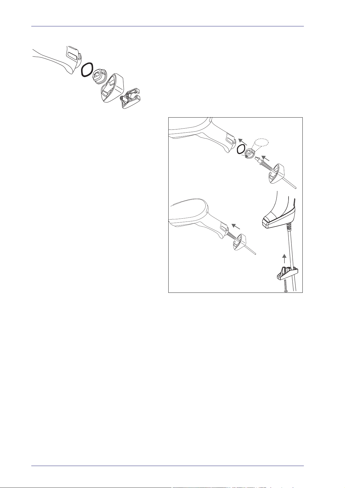
Setup
A
B
C
D
FRONT>>
1
2
3
6
4
5
7
Connecting the Cable (Corded versions)
A. Rubber gasket
B. Cable Holder
C. Cover
D. Connector Holder
1. Slip the cable through the Cover.
2. Push the Rubber Gasket onto the Cable
lder.
Ho
3. Push the Cable Holder and gasket into
handle. Ensure that the “Front”
the
marking on the Cable Holder is facing
out, with the arrow pointing towards the
front of the scanner.
4. Insert the end of the cable into the
cket of the Cable Holder.
so
5. Push the Cover along the cable towards
he reader, and hook it over the yellow
t
“tooth” on the back of the handle.
6. Insert the cable through the Connector
lder, and push it up into the Cover.
Ho
7. Insert and tighten the sc
rew to affix the
cable assembly to the reader handle.
8
Wasp WDI7500/WWS750
Page 19
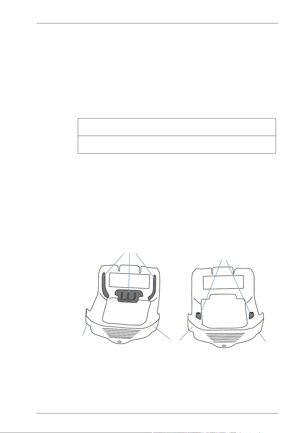
Configuring the Horizontal Base Station
Desktop Mounting Bracket
Wall Mounting Bracket
Bosses
(Horizontal )
(Vertical)
Tab
Tab
Tab
Ribs
Configuring the Horizontal Base Station
To set up your WWS750-BS Base Station you must:
1. Physically install the cradle.
2. Make all system connections.
3. Configure the WWS750-BS cradle.
Mounting the WWS750-BS Cradle
The cradle package contains the following items:
WWS750-BS Base Station (with Desktop
Mounting Bracket installed)
WWS750-BS Quick Reference Guide
(this manual)
The cradle can be either mounted on a flat surface for desktop usage or
affixed vertically to a wall.
Mounting Brackets
The cradle comes with two different mounting brackets. The appropriate
bracket is used depending on whether the cradle will be mounted on a horizontal or vertical surface. When shipped, the cradle has the Desktop Mounting Bracket installed. For vertical installation, the Wall Mounting Bracket
be attached instead.
must
Figure 1. Mounting Brackets
1 Metal Mounting plate
1 Wall Mounting Bracket
Product Reference Guide
• Desktop mount bracket has ribs to keep the scanner in place when the
cradle is horizontal.
• Wall mount bracket contains bosses to
the cradle is vertical.
keep the scanner in place when
9
Page 20
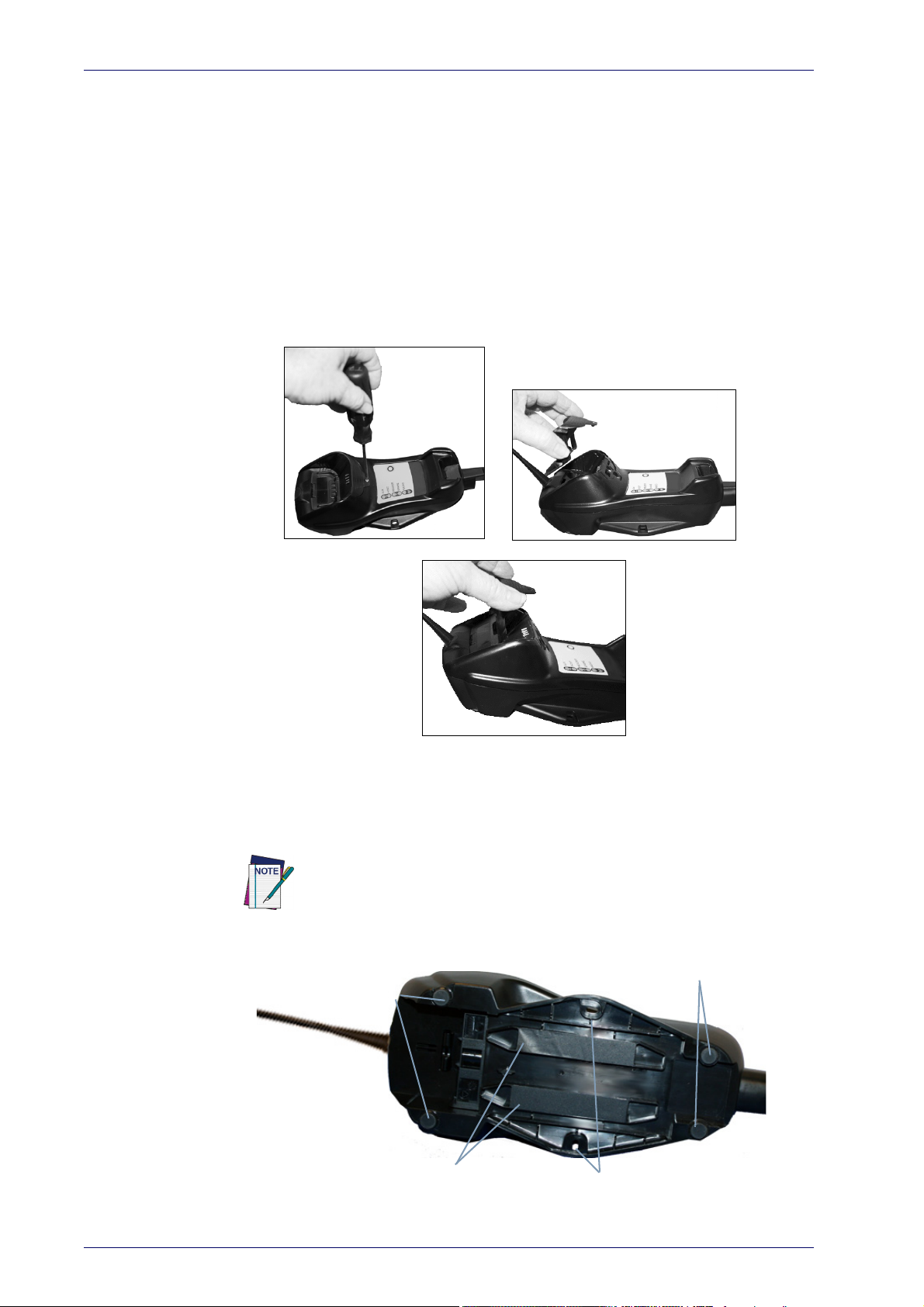
Setup
12
3
Mounting
Protective Adhesive
Rubber Feet
Rubber Feet
Strips
Holes
To change the Bracket:
1. Remove the screw holding the Bracket in place. Retain the screw for reuse.
2. Carefully lift off the Bracket.
3. Install the other bracket by first slipping the end tab into place on the
base station, then easing the tabs (shown in Figure 1 on page 9) into
place on the sides.
4. Replace the screw to secure the Bracket to the Base Station.
Figure 2. Changing the Bracket
Permanent Mounting
For either desktop or wall mounting, the cradle can be fastened directly to a
flat surface using screws (not included).
Figure 3. Base Station Bottom
When mounting on drywall, the base should be screwed to a wall stud or
supporting beam for additional support.
10
Wasp WDI7500/WWS750
Page 21
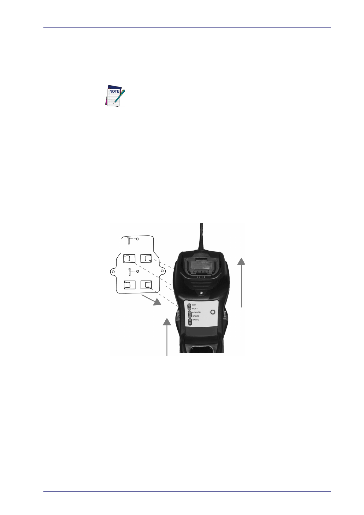
Mounting for Portable Use
If portability of the cradle is required, the metal plate must be used. There
are two ways this can be done: (1) by first mounting the metal plate on a flat
surface so the cradle can be slid off and on, or (2) mounting the metal plate
onto the back of the base station and then screwing both to the desired surface.
For additional security on wall mounting, it is strongly recommended
that the cradle be secured into place using two auxiliary screws through
the mounting holes on the side.
Mounting the Metal Plate
1. Affix the metal plate onto the desired mounting surface using the two
center screw holes (see Figure 4 on page 11).
Mounting the WWS750-BS Cradle
2. Remove the adhesive strips protecting the m
shown in Figure 3.
3. Slide the tabs on the back of the cradle onto the metal plate as shown
in
Figure 4.
4. After aligning the tabs, push up to lock into place.
ounting tabs on the cradle,
Figure 4. Mounting Plate on Wall
Product Reference Guide
11
Page 22
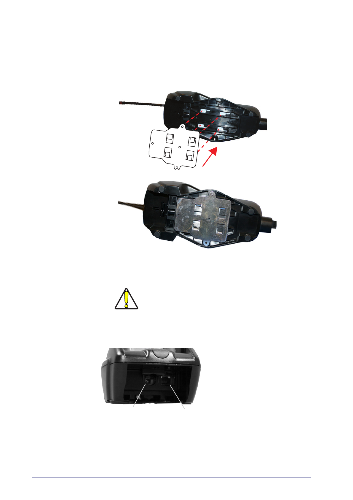
Setup
Base with Mount attached
Power Supply
Multi-Interface Connector
Attaching the Metal Plate to Base
Alternatively, the mount can be attached first to the base, then both can be
mounted to a wall as described above.
Figure 5. Attaching Mounting Plate to Base
System Connections
The WWS750-BS cradle provides a multi-interface connector and a power
supply connector as shown:
Connections should always be made with power off!
CAUTION
12
Wasp WDI7500/WWS750
Page 23
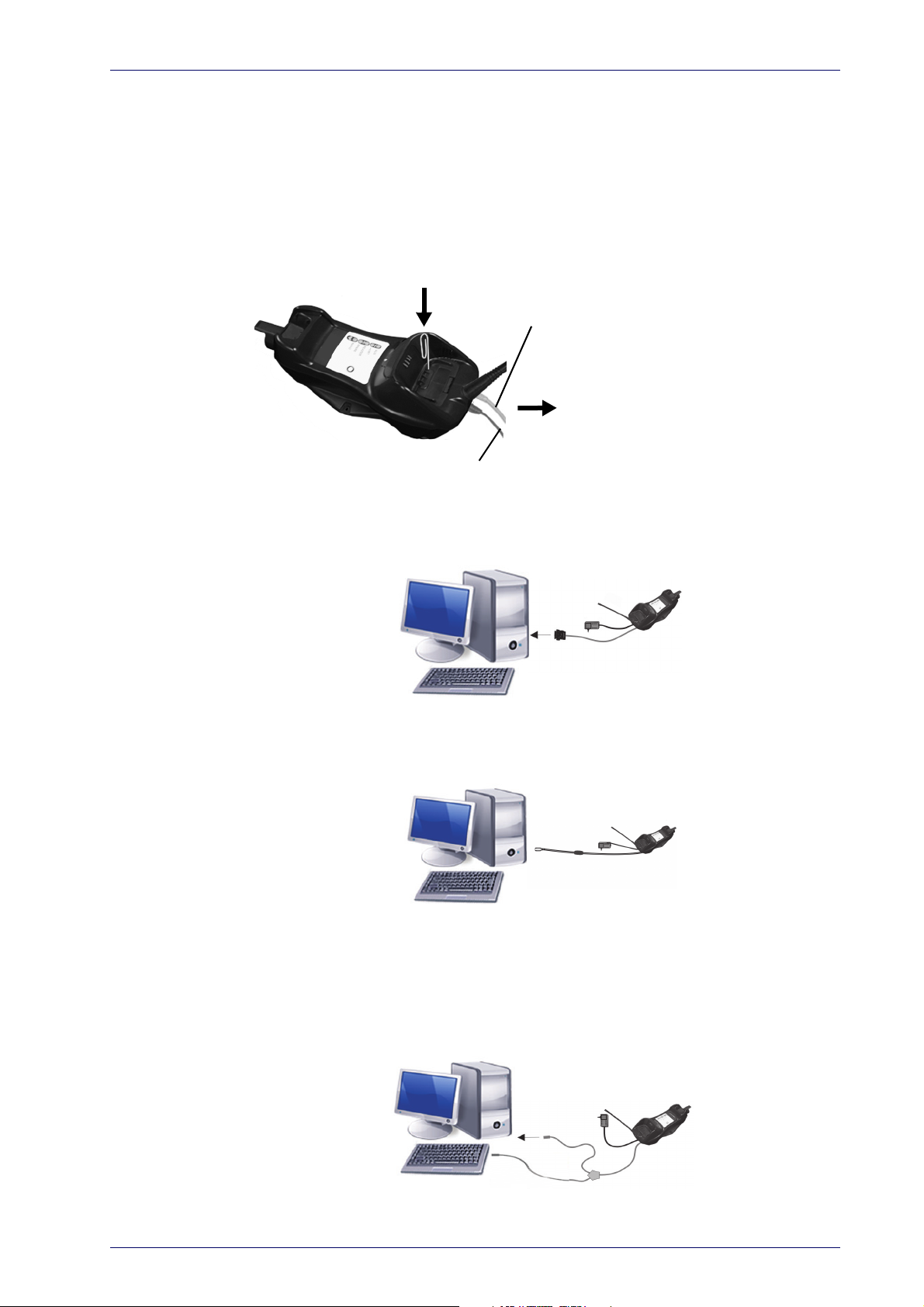
Mounting the WWS750-BS Cradle
Power
Interface Emulation to Host
Connecting/Disconnecting the Cable
Connecting and Disconnecting the Interface Cable
The WWS750-BS can be connected to a Host by means of a multi-interface
cable, which must be simply plugged into the Host connector, visible on the
front panel of the cradle.
To disconnect the cable, insert a paper clip or other similar object into the
le corresponding to the Host connector on the body of the cradle. Push
ho
down on the clip while unplugging the cable. Refer to the following figures:
RS-232
USB*
*The power supply is optional, the cradle can be powered by the USB port. In
this case the full charging of an empty battery will take about 10 hours. For
intense usage and/or when the system is shut down during the night, the
use of an external power supply is recommended.
WEDGE
Product Reference Guide
13
Page 24
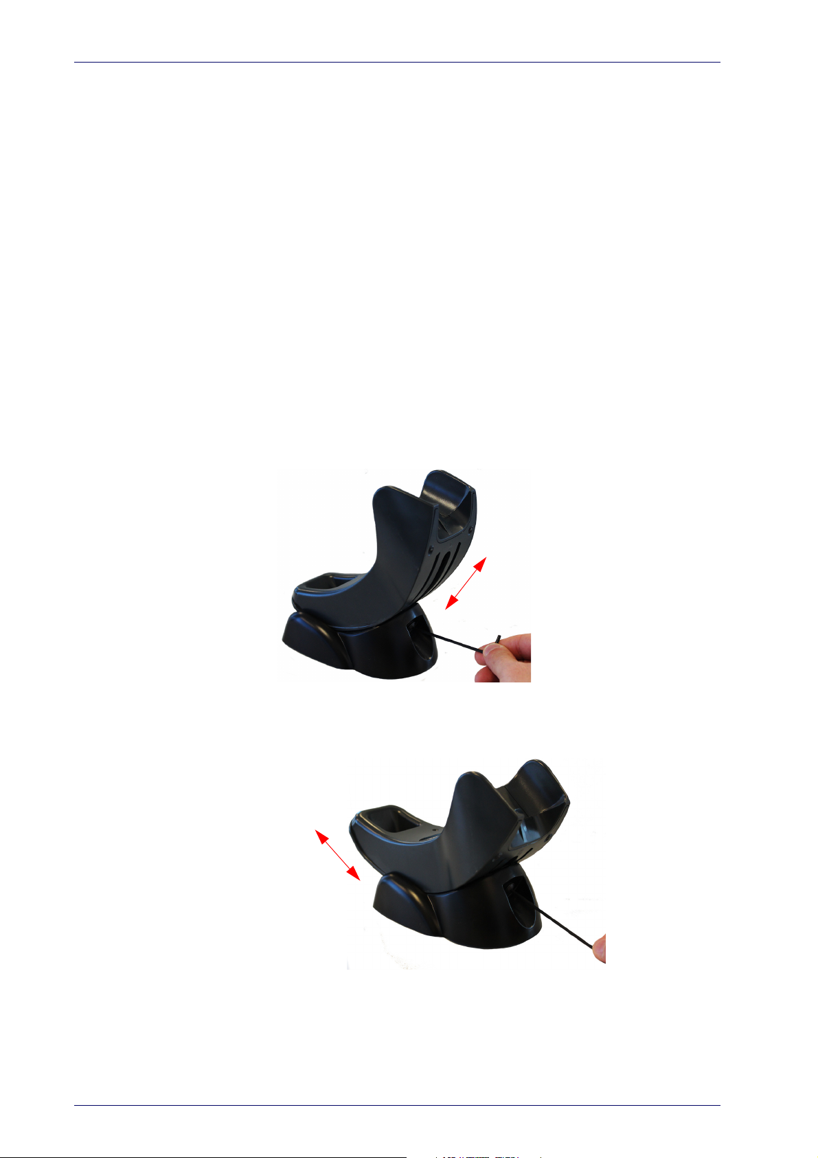
Setup
Configuring the Vertical Base Station
Installation
To set up your WWS750-BS cradle you must:
1. Physically install the cradle.
2. Make all system connections.
3. Configure the WWS750-BS cradle.
The cradle package contains the following items:
• WWS750-BS Presentation Base •Hex Key
• WWS750-BS Quick Reference Guide • Rubber Spacers
• Metal Mounting Plate
Regulating the Cradle Position
To regulate the position, use the hex key to unscrew the holder and slide it
to the desired position.
14
Wasp WDI7500/WWS750
Page 25
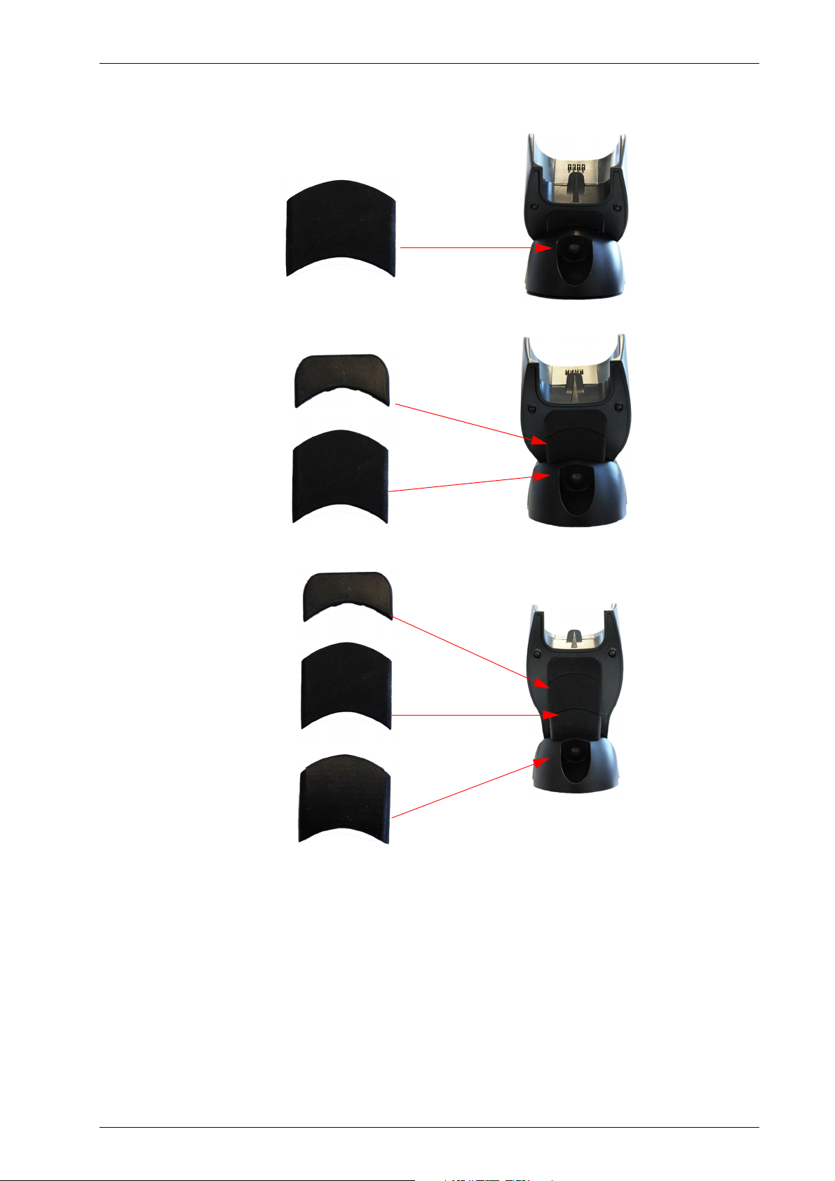
Mounting the WWS750-BS Cradle
The rubber spacers included in the box can be used to fix the position of the
cradle:
Product Reference Guide
15
Page 26
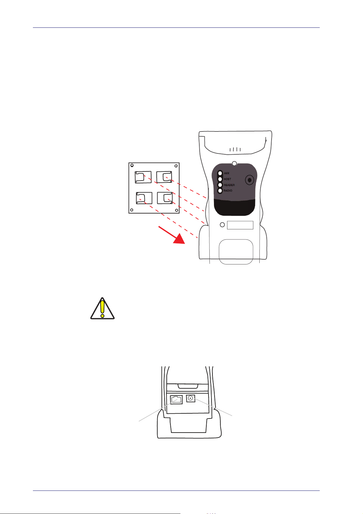
Setup
Power Supply
Multi-Interface
Connector
Mounting with the Metal Plate
1. Affix the metal plate onto the desired mounting surface using the two
center screw holes (see Figure 1 on page 4).
2. Slide the tabs on the back of the cradle onto the metal plate as shown
in Fi
gure 1.
3. After aligning the tabs, push up t
Figure 6. Mounting Plate on Wall
o lock into place.
System Connections
Connections should always be made with power off!
CAUTION
The WWS750-BS Base Station provides a multi-interface connector and a
power supply connector as shown:
16
Wasp WDI7500/WWS750
Page 27
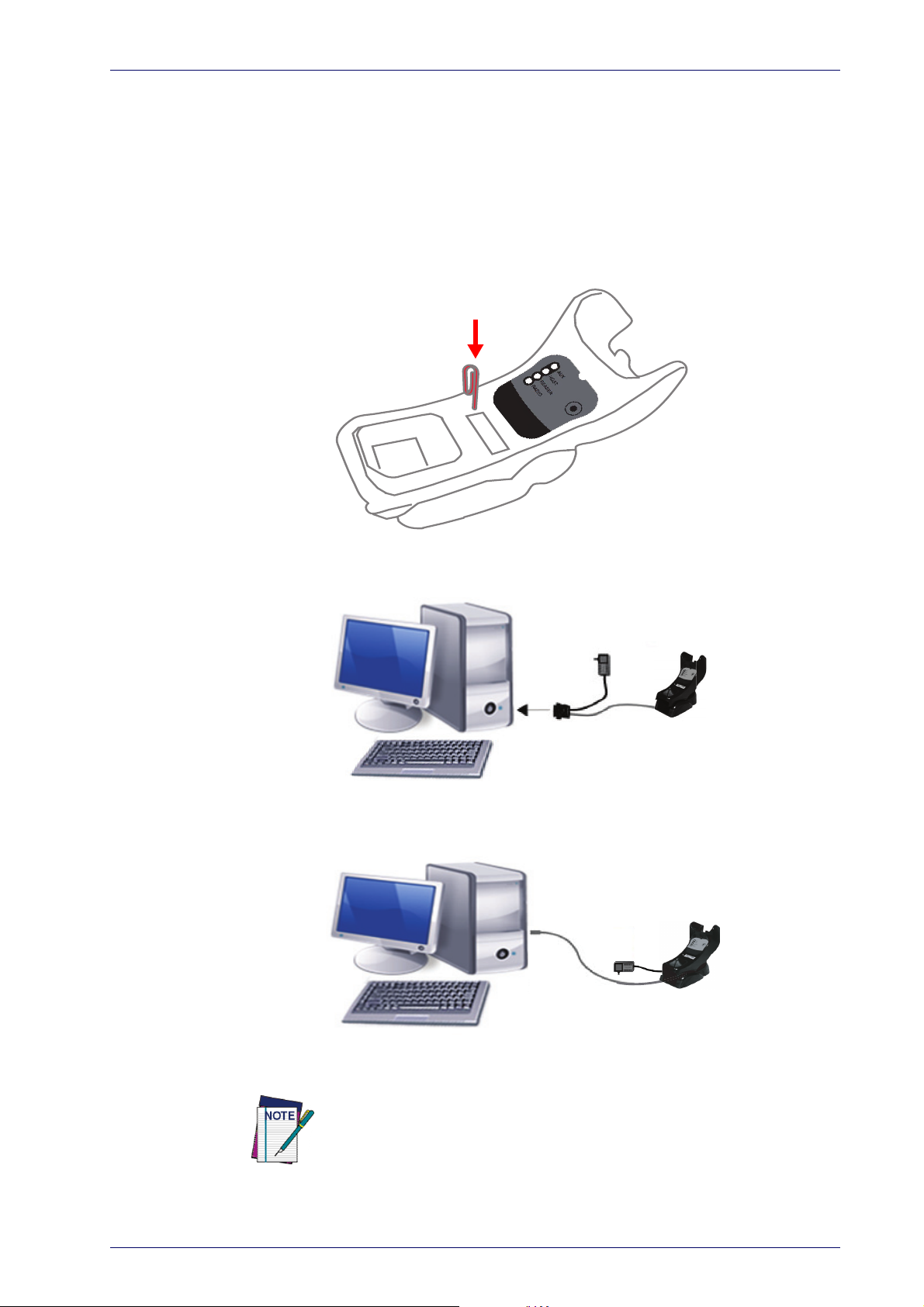
Mounting the WWS750-BS Cradle
Connecting/Disconnecting the Cable
Connecting and Disconnecting the Interface Cable
The WWS750-BS can be connected to a Host by means of a multi-interface
cable, which must be simply plugged into the Host connector, visible on the
front panel of the cradle.
To disconnect the cable, insert a paper clip or other similar object into the
ho
le corresponding to the Host connector on the body of the cradle. Push
down on the clip while unplugging the cable. Refer to the following figure:
RS-232
USB
The power supply is required only if you need to connect the interface
cable to a standard USB Port. The power supply is not required if you connect the interface cable to a Powered USB 12V or 24V port.
Product Reference Guide
17
Page 28

Setup
WWS750-BS Configuration
The WWS750-BS configuration can be performed either by sending configuration strings from the Host PC via the RS-232 or USB-COM interface or by
ding configuration barcodes with the WWS750 reader.
rea
Serial Configuration
By connecting the WWS750-BS to a PC through an RS-232 or USB-COM
interface cable it is possible to send configuration strings from the PC to the
WWS750-BS.
Configuration Barcodes
Link the cradle and the reader using the procedures described in the
WWS750 Quick Reference. Once the pairing is complete, you can configure
the WWS750-BS cradle by reading configuration barcodes in this manual.
To configure the WWS750-BS using the Wasp reader (paired to the cradle
h the Bind command), follow the procedure according to the interface
wit
selected.
Interface Selection
Upon completing the physical connection between the reader and its host,
proceed to Table 2 on page 19 to select the interface type the reader is connected to (for example: RS-232, Keyboard Wedge, USB, etc.). Scan the
appropriate barcode in that se
face type.
Setting the Interface
Scan the programming barcode from this section which selects the appropriate interface type matching the system the reader will be connected to.
ext, proceed to the corresponding section in this manual (also listed in
N
Table 2 on page 19) to configure any desired settings and fea
ated with that interface.
Unlike some programming features and options, interface selections
require that you scan only one programming barcode label. DO NOT scan an
ENTER/EXIT barcode prior to scanning an interface selection barcode.
Some interfaces require the scanner to start in the disabled state when
powered up.
state, pull the trigger and hold it for five seconds. The scanner will change to
a state that allows programming with barcodes.
ction to configure your system’s correct inter-
tures associ-
If additional scanner configuration is desired while in this
18
Wasp WDI7500/WWS750
Page 29
Interface Selection
$P,HA12,P(CR)
$P,HA13,P(CR)
$P,HA47,P(CR)
$P,HA45,P(CR)
$P,HA35,P(CR)
$P,HA2B,P(CR)
$P,HA2C,P(CR)
Table 2. Available Interfaces
RS-232 FEATURES
RS-232 standard interface
Select RS232-WN
RS-232 for use with OPOS/UPOS/JavaPOS
Select RS232-STD
RS-232 Wincor-Nixdorf
Select RS-232 OPOS
Set RS-232
Interface
Features
starting
on page
28
USB FEATURES
USB Com to simulate RS-232 standard interface
Select USB COM-STD
USB-OEM
(can be used for OPOS/UPOS/JavaPOS)
a
Select USB-OEM
Set USB-OEM
Interface
USB Keyboard with standard key encoding
Features
starting
Select USB Keyboard
on page
49
USB Keyboard with alternate key encoding
Select USB Alternate Keyboard
USB Keyboard for Apple computers
Select USB-KBD-APPLE
a. Download the correct USB Com driver from www.waspbarcode.com
Product Reference Guide
19
Page 30
$P,HA2B,P(CR)
$P,HA2C,P(CR)
$P,HA29,P(CR)
$P,HA11,P(CR)
$P,HA26,P(CR)
$P,HA10,P(CR)
Setup
KEYBOARD
USB Keyboard with alternate key encoding
Select USB-KBD-APPLE
AT, PS/2 25-286, 30-286, 50, 50Z, 60, 70, 80, 90 &
5 w/Standard Key Encoding
9
Select KBD-AT-NK
Select USB Alternate Keyboard
USB Keyboard for Apple computers
Select KBD-AT
Keyboard Wedge for IBM AT PS2 with
st
andard key encoding but without
external keyboard
FEATURES
Set KEYBOARD
WEDGE
Interface
Features
starting on
page 40
AT, PS/2 25-286, 30-286, 50, 50Z, 60, 70, 80, 90 &
w/Alternate Key
95
Select KBD-AT-ALT-NK
Select KBD-AT-ALT
Keyboard Wedge for IBM AT PS2 with
a
lternate key encoding but without
external keyboard
20
Wasp WDI7500/WWS750
Page 31

Customizing Configuration Settings
Transmit Software Version
RevA\r
Configure Interface Settings
If after scanning the interface barcode from the previous table, your installation requires you to select options to further customize your reader, turn to
he appropriate section for your interface type in "Configuration Parameters"
t
starting on page 25.
Global Interface Features
See "Global Interface Features" on page 27 for settings configurable by all
interface types.
Configuring Other Features
If your installation requires different programming than the standard factory
default settings, the following sections of this manual allow configuration of
non-interface-specific settings you might require. Go to Configuration
Using Barcodes, starting on page 25 for a complete list of available options.
Customizing Configuration Settings
Software Version Transmission
The software version of the device can be transmitted over the RS-232 and
Keyboard interfaces by scanning the following label.
Self Test and Statistics
The internal status of the reader can be accessed in COM interfaces giving
the following command string through a Terminal Emulator program:
$S,yX,s[CR](corded reader only).
Product Reference Guide
21
Page 32

Setup
Restore Custom Default Configuration
$P,HA00,P(CR)
Resetting the Product Configuration to Defaults
Restore Custom Defaults
If you aren’t sure what programming options are in your imager, or you’ve
changed some options and want to restore the Custom Default Configuration that may have been saved in the scanner, scan the Restore Custom
fault Configuration barcode below. This will restore the custom configu-
De
ration for the currently active interface.
Custom defaults are based on the interface type. Configure the
imager for the correct interface before scanning this label.
Restore Factory Configuration
The "Restore Custom Default Configuration" command above is normally
enough to restart the machine from a known status (set in the factory or by
the customer via configuration file). The machine is set as it arrived to you
from the factory or according to the custom configuration file you loaded
afterward.
If you want to
use "Restore Factory Configuration" on page 286 of this manual.
The programming items listed in the following sections show the factory
d
efault settings for each of the menu commands. If no configuration file has
been loaded, the above command restores the factory default.
Set Date and Time
1. Scan the Enter/Exit Programming barcode below to set date and time.
permanently cancel the setup defined by the configuration file
ENTER/EXIT PROGRAMMING MODE
22
2. Scan the Set Date barcode + six
digits for Year, Month and Day
(YYMMDD) from Appendix D,
Keypad.
3. Scan Set Time + six digits for
Hours, Minutes and Seconds
(HHMMSS) from Appendix D,
Keypad.
Set Time
4. Scan the Enter/Exit Programming barcode to complete.
Set Date
Wasp WDI7500/WWS750
Page 33

Linking the Reader
Unlink
Enable RF Link to Server
Linking the Reader
Link RF Devices to Base
For RF devices, before configuring the interface it is necessary to link the
handheld with the base.
To link the handheld and the base, press the trigger to wake up the handheld and mount it into the base. If the reader was previously linked to
another base, you must first
onds), then scan the
Unlink
Linking to a Bluetooth Adapter in Serial Port Profile (Slave) Mode
1. Install any drivers provided with the Bluetooth adapter.
press and hold the button on the base (>5 sec-
barcode before re-linking to the new base.
2. Scan the
Enable RF Link to Server
label below to make the scanner visible
to the host computer.
3. Use the host computer’s Bluetooth manager to “Discover new devices”
and select "Wasp
Scanner." If you receive an error message, it may be
necessary to disable security on the device.
4. Use an RS-232 terminal program to see incoming data on the port designated by the computer's Bluetooth manager.
Linking to a Bluetooth Adapter in Serial Port Profile (Master) Mode
1. Ensure the PC or terminal can network with Bluetooth devices and that
it is powered on.
2. Ensure that a COM port is assigned un
setup menu.
der Services in the Bluetooth
3. Create a Link label that contains the address of the PC Bluetooth
pter.
ada
The link label is a Code 128 function 3 label with the following format:
<FN3 char>LnkB<12 character Bluetooth address>
4. Scan the link label you created in step 3.
The Bluetooth address can be found under “Properties” within the Bluetooth
setup menu.
Product Reference Guide
23
Page 34

Setup
Link to PC in HID
Linking to a Bluetooth Adapter in HID mode
1. Install any drivers provided with the Bluetooth adapter.
Power Off
2. Scan the
3. Use the host computer’s Bluetooth m
Link to PC in HID
label below.
anager to “Discover new devices”
and select "Wasp Scanner." If you receive an error message, it may be
necessary to disable security on the device.
4. Use a text editor to see incoming data on the port designated by the
omputer's Bluetooth manager.
c
The Wasp Retail WWS750 can be set up to require a PIN code when connecting. If you want to set up a PIN, or when adding new equipment to a system
that
uses a custom security PIN, please see
"Bluetooth PIN Code"
start-
ing on page 218 for more information.
Scan the barcode below to shut off power to the handheld until the next
trigger pull
. This function only applies to the wireless models.
PowerOff
24
Wasp WDI7500/WWS750
Page 35

Configuration Using Barcodes
This and following sections provide programming barcodes to configure
your reader by changing the default settings.
You must first enable your scanner to read barcodes in order to use
this section. If you have not done this, go to
page 7
Configuration Parameters
Once the reader is set up, you can change the default parameters to meet
your application needs. Refer to "Standard Defaults" starting
initial configuration in order to set the default values and select the interface
for
your application.
The following configuration parameters are divided into logical groups,
making it easy to find the desired function based on its reference group.
Interface Configuration
Chapter 3
Setup, starting on
and complete the appropriate procedure.
on page 275 for
• "RS-232 Only Interface" on page 28
• "RS-232/USB-Com Interfaces" on
• "Keyboard EMULATION Settings" on
page 33
page 40
Parameters common to all interface applications:
• "Data Format" on page 51 gives options to control the messages sent to
the Host system by selec
sent to the handheld.
• "Reading Parameters" on
indicators status functioning such as programming for scanning,
beeper and LED indicators and ot
• "Motion Features" on
settings for the handheld.
ting parameters to control the message strings
page 65 control various operating modes and
her universal settings.
page 198 provide the ability to configure motion
Wireless-Only Features
• Wireless Features, starting on page 200
• Bluetooth Features, starting on page 217
Symbology-specific parameters
• "1D Symbologies" on page 83 provides configuration of a personalized
mix of 1D codes, code families and their options.
• "2D Symbologies" on
ized mix of 2D codes, code fa
page 166 provides configuration of a personal-
milies and their options.
Product Reference Guide
25
Page 36

Configuration Using Barcodes
To program features:
1. Scan the ENTER/EXIT PROGRAMMING barcode, available at the top of
each programming page, when applicable.
2. Scan the barcode to set the desired programming feature. You may
eed to cover unused barcodes on the page, and possibly the facing
n
page, to ensure that the reader reads only the barcode you intend to
scan.
You must first enable your reader to read barcodes in order to use
this section. If you have not done this, go to
page 7
and complete the appropriate procedure.
Setup, starting on
3. If additional input parame
and scan the appropriate characters from the keypad.
ters are needed, go to Appendix D, Keypad,
Additional information about many features can be found in the “References” chapter.
If you make a mistake before the last
character, scan the CANCEL bar-
code to abort and not save the entry string. You can then start again
e beginning.
at th
4. Complete the programming sequence by scanning the ENTER/EXIT
PROGRAMMING barcode to exit Programming Mode.
For more detailed descriptions, programming informat
setting selected configuration items, see References, starting on page 228.
ion and examples for
26
Wasp WDI7500/WWS750
Page 37

Enter/Exit Programming Mode
$CIFIH00(CR)
$CIFIH01(CR)
$CUSSE00(CR)
$CUSSE01(CR)
GLOBAL INTERFACE FEATURES
The following interface features are configurable by all interface types.
Host Commands — Obey/Ignore
This option specifies whether the reader will obey or ignore host commands. When set to ignore, the reader will ignore all host commands except
ose necessary for:
th
•service mode
• flash programming mode
•keeping the inte
• transmission of labels.
rface active
DEFAULT
Host Commands = Obey
(Do Not Ignore Host Commands)
Host Commands = Ignore
USB Suspend Mode
This setting enables/disables the ability of USB interfaces to enter suspend
mode.
DEFAULT
USB Suspend Mode = Disable
USB Suspend Mode = Enable
Product Reference Guide
27
Page 38

RS-232 ONLY INTERFACE
BAUD RAT E on page 29
DATA BITS on page 30
STOP BITS on page 30
PARITY on page 31
HANDSHAKING CONTROL on page 32
Use the programming barcodes in this section if modifications to the standard RS-232 interface settings are necessary to meet your system’s requirements. Additional settings which apply to
interfaces are available in the next section, "RS-232/USB-Com Interfaces"
starting on page 33.
Reference Appendix C, Standard Defaults for a listing of standard factory
settings.
both the RS-232 and USB
28
Wasp WDI7500/WWS750
Page 39

Baud Rate
$CR2BA00(CR)
$CR2BA01(CR)
$CR2BA02(CR)
$CR2BA03(CR)
$CR2BA04(CR)
$CR2BA05(CR)
$CR2BA06(CR)
$CR2BA07(CR)
See page 229 for information on this feature.
Baud Rate = 2400
Enter/Exit Programming Mode
Baud Rate = 1200
Baud Rate = 4800
Baud Rate = 9600
Baud Rate = 38,400
Baud Rate = 115,200
Baud Rate = 19,200
Baud Rate = 57,600
DEFAULT
Product Reference Guide
29
Page 40

Enter/Exit Programming Mode
$CR2DA00(CR)
$CR2DA01(CR)
DEFAULT
DEFAULT
$CR2ST00(CR)
$CR2ST01(CR)
Data Bits
This parameter allows the reader to interface with devices requiring a 7-bit
or 8-bit ASCII protocol for sending and receiving data.
8 Data Bits
7 Data Bits
Stop Bits
Set the number of stop bits to match host device requirements. See
page 229 for more information on
2 Stop Bits
this feature.
1 Stop Bit
30
Wasp WDI7500/WWS750
Page 41

Enter/Exit Programming Mode
$CR2PA00(CR)
$CR2PA01(CR)
$CR2PA02(CR)
Parity
This feature specifies parity required for sending and receiving data. Select
the parity type according to host device requirements. See page 229 for
more information.
DEFAULT
Parity = None
Parity = Even
Parity = Odd
Product Reference Guide
31
Page 42

Enter/Exit Programming Mode
DEFAULT
$CR2HC00(CR)
$CR2HC01(CR)
$CR2HC02(CR)
$CR2HC03(CR)
$CR2HC04(CR)
Handshaking Control
See page 229 for more information about this feature.
Handshaking Control = RTS/CTS
Handshaking Control = RTS
Handshaking Control = RTS/XON/XOFF
Handshaking Control = RTS On/CTS
Handshaking Control = RTS/CTS Scan Control
32
Wasp WDI7500/WWS750
Page 43

RS-232/USB-COM INTERFACES
INTERCHARACTER DELAY on page 34
BEEP ON ASCII BEL on page 34
BEEP ON NOT ON FILE on page 35
ACK NAK OPTIONS on page 35
ACK CHARACTER on page 36
NAK CHARACTER on page 36
ACK NAK TIMEOUT VALUE on page 37
ACK NAK RETRY COUNT on page 37
ACK NAK ERROR HANDLING on page 38
INDICATE T RANSMISSION FAILURE on page
38
DISABLE CHARACTER on page 39
ENABLE CHARACTER on page 39
The programming barcodes in this chapte
dard RS-232 and USB-Com interfaces. Reference Appendix C, Standard
Defaults for a listing of standard factory settings.
r allow modifications to the stan-
Product Reference Guide
33
Page 44

Enter/Exit Programming Mode
$CR2IC00(CR)
$CR2IC
~
DEFAULT
00 = No Intercharacter Delay
$CR2BB00(CR)
$CR2BB01(CR)
Intercharacter Delay
This parameter specifies the intercharacter delay between the end of one
character and the beginning of the next. The delay can be set within a range
of zero (0) to 990 milliseconds in 10ms increments. A setting of zero specifies no delay.
See page 238 for more information.
Select Intercharacter Delay Setting
Intercharacter Delay = No Delay
To configure this feature, scan the ENTER/EXIT
PROGRAMMING MODE barcode above, then the barcode at left followed by the digits from the Alphanumeric characters in
representing your desired char
ning the ENTER/EXIT barcode again.
Appendix D, Keypad
acter(s). End by scan-
Make a mistake? Scan the CANCEL barcode to abort and
not save the entry string. You can then start again at the
beginning.
Beep On ASCII BEL
When this parameter is enabled, the reader issues a beep when a <BEL>
character is detected on the RS-232 serial line. <BEL> is issued to gain a
user's attention to an illegal entry or other important event.
CANCEL
DEFAULT
34
Beep On ASCII BEL = Disable
Beep On ASCII BEL = Enable
Wasp WDI7500/WWS750
Page 45

Enter/Exit Programming Mode
$CBPNF00(CR)
$CBPNF01(CR)
$CR2AE00(CR)
$CR2AE01(CR)
$CR2AE02(CR)
$CR2AE03(CR)
Beep On Not on File
This option enables/disables the action of the reader to sound a three beep
sequence upon receiving a Not-On-File (NOF) host command.
Beep On Not On File = Disable
DEFAULT
Beep On Not On File = Enable
ACK NAK Options
This enables/disables the ability of the reader to support the RS-232 ACK/
NAK protocol.
See page 231 for more information.
DEFAULT
ACK/NAK Protocol = Enable for label transmission
ACK/NAK Protocol = Enable for label transmission and
host-command acknowledge
ACK/NAK Protocol = Disable ACK/NAK
ACK/NAK Protocol = Enable for host-command
acknowledge
Product Reference Guide
35
Page 46

Enter/Exit Programming Mode
$CR2AC
0x06 ‘ACK’ Character
$CR2NA
0x15 ‘NAK’ Character
ACK Character
This setting specifies an ASCII character or hex value to be used as the ACK
character. ASCII characters or any hex value from 0 to 0xFF can be selected.
See page 231 for more information.
Setting to previously defined characters such as XON, XOFF, or host commands conflicts with
normal operation of these characters. 8-bit data is not recognized when the option
has been set as 7 Data Bits.
Select ACK Character Setting
DEFAULT
Data Bits
NAK Character
This setting specifies an ASCII character or hex value to be used as the NAK
character. ASCII characters or any hex value from 0 to 0xFF can be selected.
Setting to previously defined characters such as XON, XOFF, or host commands conflicts with
normal operation of these characters. 8-bit data is not recognized when the option
has been set as 7 Data Bits.
See page 232 for more information.
Select NAK Character Setting
Data Bits
DEFAULT
36
Wasp WDI7500/WWS750
Page 47

ACK NAK Timeout Value
$CR2AT
~
01 ACK NAK Timeout value is 200ms
$CR2AR
~
DEFAULT
003 = 3 Retries
This option specifies the amount of time the reader waits for an ACK character from the host following label transmission. The selectable timeout
nge is 200 milliseconds to 15,000ms (15 seconds) in 200ms increments.
ra
A selection of 0 disables the timeout.
See page 233 for more information on setting this feature.
Select ACK NAK Timeout Value Setting
Make a mistake? Scan the CANCEL barcode to abort
and not
again at the beginning.
save the entry string. You can then start
Enter/Exit Programming Mode
To configure this feature, scan the ENTER/EXIT
PROGRAMMING MODE barcode above, then the barcode at left followed by the digits from the Alphanumeric characters in
representing your desired character(s). End by scanning the ENTER/EXIT barcode
Appendix D, Keypad
again.
CANCEL
DEFAULT
ACK NAK Retry Count
This feature specifies the number of times the reader retries a label transmission due to a retry condition. The selectabl
retries. A selection of 0 disables the count, and a selection of 255 specifies
unlimited retries. See page 234 for more information.
Select ACK NAK Retry Count Setting
Make a mistake? Scan the CANCEL barcode to abort
and not
again at the beginning.
save the entry string. You can then start
e range is from 1 to 254
To configure this feature, scan the ENTER/EXIT
PROGRAMMING MODE barcode above, then the barcode at left followed by the digits from the Alphanumeric characters in
representing your desired character(s). End by scanning the ENTER/EXIT barcode
Appendix D, Keypad
again.
CANCEL
Product Reference Guide
37
Page 48

Enter/Exit Programming Mode
DEFAULT
$CR2EH00(CR)
$CR2EH01(CR)
$CR2EH02(CR)
$CR2TF00(CR)
$CR2TF01(CR)
DEFAULT
ACK NAK Error Handling
This feature specifies the method the reader uses to handle receive errors
detected while waiting for an ACK character from the host.
ACK NAK Error Handling = Process Error as Valid ACK Char-
acter
ACK NAK Error Handling = Ignore Errors Detected
Indicate Transmission Failure
This option enables/disables the reader’s ability to sound an error beep to
indicate a transmission failure while in ACK/NAK mode
Indicate Transmission Failure = Enable Indication
ACK NAK Error Handling = Process Error as
Valid NAK Character
.
Indicate Transmission Failure = Disable Indication
38
Wasp WDI7500/WWS750
Page 49

Enter/Exit Programming Mode
$CR2DC
0x44 = Disable Character is ‘D’
$CR2EC
DEFAULT
0x45 = Enable Character is ‘E’
Disable Character
Specifies the value of the RS-232 host command used to disable the reader.
ASCII characters or any hex value fr
Setting to previously defined characters such as XON, XOFF, or host commands conflicts
with normal operation of these characters. 8-bit data is not recognized when the option
Data Bits
See page 235 for more information on setting this feature.
Select Disable Character Setting
has been set as 7 Data Bits.
om 0 to 0xFF can be selected.
DEFAULT
Enable Character
Specifies the value of the RS-232 host command used to enable the reader.
ASCII characters or any hex value fr
Setting to previously defined characters such as XON, XOFF, or host commands conflicts with normal operation of these characters. 8-bi
Data Bits
option
See page 236 in “References” for more information on setting this feature.
Select Enable Character Setting
has been set as 7 Data Bits.
om 0 to 0xFF can be selected.
t data is not recognized when the
Product Reference Guide
39
Page 50

KEYBOARD EMULATION SETTINGS
COUNTRY MODE on page 41
SEND CONTROL CHARACTERS on page 44
WEDGE QUIET INTERVAL on page 45
INTERCODE DELAY on page 45
CAPS LOCK STATE on page 46
NUMLOCK on page 46
USB KEYBOARD SPEED on page 47
USB KEYBOARD NUMERIC KEYPAD on page 48
Use the programming barcodes in this ch
board and Wedge Interfac
listing of standard factory settings.
Information about control c
interfaces is listed in Appendix E, Scancode Tables.
es. Reference Appendix C, Standard Defaults for a
haracter emulation which applies to keyboard
apter to select options for USB Key-
40
Wasp WDI7500/WWS750
Page 51

Enter/Exit Programming Mode
DEFAULT
$CKBCO00(CR)
$CKBCO01(CR)
$CKBCO02(CR)
$CKBCO11(CR)
$CKBCO0E(CR)
$CKBCO03(CR)
$CKBCO04(CR)
Country Mode
This feature specifies the country/language supported by the keyboard.
Several languages are supported:
Country Mode = U.S.
Country Mode = Belgium
Country Mode = Croatia
Supports only the interfaces listed in the Country
Mode feature description.
Country Mode = Denmark
Country Mode = Britain
Supports only the interfaces listed in the
Country Mode feature description.
Country Mode = Czech Republic
Supports only the interfaces listed in the Country Mode feature description.
Country Mode = France
Product Reference Guide
41
Page 52

Enter/Exit Programming Mode
$CKBCO13(CR)
$CKBCO05(CR)
$CKBCO0D(CR)
$CKBCO06(CR)
$CKBCO0C(CR)
$CKBCO14(CR)
$CKBCO07(CR)
Country Mode (continued)
Supports only the interfaces listed in the Country
Mode feature description.
Country Mode = Germany
Supports only the interfaces listed in the Country
Mode feature description.
Country Mode = French Canadian
Country Mode = Italy
Supports only the interfaces listed in the Country
Mode feature description.
Country Mode = Lithuanian
Country Mode = Hungary
Country Mode = Japanese 106-key
Supports only the interfaces listed in the Country Mode feature description.
42
Country Mode = Norway
Wasp WDI7500/WWS750
Page 53

Country Mode (continued)
$CKBCO12(CR)
$CKBCO08(CR)
$CKBCO10(CR)
$CKBCO0F(CR)
$CKBCO09(CR)
$KBCO0A(CR)
$CKBCO0B(CR)
Country Mode = Poland
Supports only the interfaces listed in the Country
Mode f
eature description.
Enter/Exit Programming Mode
Supports only the interfaces listed in the Country Mode feature description.
Country Mode = Portugal
Supports only the interfaces listed in the Country Mode feature description.
Country Mode = Romania
Supports only the interfaces listed in the Country
Mode f
eature description.
Country Mode = Spain
Country Mode = Slovakia
Country Mode = Sweden
Supports only the interfaces listed in the Country Mode feature description.
Country Mode = Switzerland
Product Reference Guide
43
Page 54

Enter/Exit Programming Mode
DEFAULT
$CKBSC00(CR)
$CKBSC01(CR)
$CKBSC02(CR)
Send Control Characters
This feature specifies how the reader transmits ASCII control characters to
the host. Reference Appendix E, Scancode Tables for more information
about control characters.
Options are as follows:
Control Character 00 :
ter Ctrl+Keys, special keys are loca
Control Character 01 :
ter Ctrl+Shift, special keys are loca
Control Character 02 :
from 0x80 to 0xFE are intended as an extended ASCII table (see "Microsoft
Windows Codepage 1252" on
Wedge Send Control Characters = 01
Characters from 00 to 0x1F are sent as control charac-
ted from 0x80 to 0xA1.
Characters from 00 to 0x1F are sent as control charac-
ted from 0x80 to 0xA1.
Special keys are located from 00 to 0x1F and characters
page 298).
Wedge Send Control Characters = 00
44
Wedge Send Control Characters = 02
Wasp WDI7500/WWS750
Page 55

Wedge Quiet Interval
$CKBQI
~
DEFAULT
0A = Quiet Interval is
100 milliseconds
$CKBID
~
00 = No Wedge Intercode Delay
Specifies amount of time to look for keyboard activity before scanner breaks
keyboard connection in order to transmit data to host. The selectable range
for this setting is 00 to 990 milliseconds (00-0x63 by 01) in increments of
ten milliseconds.
examples for setting this feature.
Set Wedge Quiet Interval
Make a mistake? Scan the CANCEL barcode to
bort and not save the entry string. You can
a
then start again at the beginning.
See page 237 in “References” for detailed information and
Enter/Exit Programming Mode
To configure this feature, scan the ENTER/EXIT
PROGRAMMING MODE barcode above, then
the barcode at left followed by the digits from
the Alphanumeric characters in
Keypad representing your desired character(s).
End by scanning the ENTER/EXIT barcode
aga
in.
CANCEL
Appendix D,
Intercode Delay
Specifies the delay between labels transmitted to the host for this interface.
The selectable range for this feature is from 0 to 99 seconds.
See page 239 in “References” for detailed information and examples for setting this feature.
Set Intercode Delay
Make a mistake? Scan the CANCEL barcode to
bort and not save the entry string. You can
a
then start again at the beginning.
To configure this feature, scan the ENTER/EXIT
PROGRAMMING MODE barcode above, then
the barcode at left followed by the digits from
the Alphanumeric characters in
Keypad
representing your desired character(s).
Appendix D,
End by scanning the ENTER/EXIT barcode
in.
aga
CANCEL
DEFAULT
Product Reference Guide
45
Page 56

Enter/Exit Programming Mode
DEFAULT
$CKBCL00(CR)
$CKBCL01(CR)
$CKBCL02(CR)
DEFAULT
$CKBNL00(CR)
$CKBNL01(CR)
Caps Lock State
This option specifies the format in which the reader sends character data.
This does not apply when an alternate key encoding keyboard is selected.
Caps Lock State = Caps Lock ON
Caps Lock State = Caps Lock OFF
Caps Lock State = AUTO Caps Lock Enable
Numlock
This option specifies the setting of the NUMLOCK key in the Keyboard
Wedge interface.
Numlock = NUMLOCK key unchanged
Numlock = Numlock key toggled
46
Wasp WDI7500/WWS750
Page 57

Enter/Exit Programming Mode
$CKBSP01(CR)
$CKBSP02(CR)
$CKBSP03(CR)
$CKBSP04(CR)
$CKBSP05(CR)
$CKBSP06(CR)
USB Keyboard Speed
This option specifies the USB poll rate for a USB keyboard.
This feature applies ONLY to the USB Keyboard interface.
DEFAULT
USB Keyboard Speed = 1ms
USB Keyboard Speed = 2ms
USB Keyboard Speed = 4ms
USB Keyboard Speed = 6ms
USB Keyboard Speed = 3ms
USB Keyboard Speed = 5ms
Product Reference Guide
47
Page 58

$CKBSP07(CR)
$CKBSP08(CR)
$CKBSP09(CR)
$CKBSP0A(CR)
Enter/Exit Programming Mode
DEFAULT
$CKBKP00(CR)
$CKBKP01(CR)
USB Keyboard Speed (continued)
USB Keyboard Speed = 8ms
USB Keyboard Speed = 7ms
USB Keyboard Speed = 9ms
USB Keyboard Speed = 10ms
USB Keyboard Numeric Keypad
This option Controls whether numeric characters will be sent using standard
keys or the numeric keypad.
Standard Keys
Numeric Keypad
48
Wasp WDI7500/WWS750
Page 59

USB-OEM INTERFACE
USB-OEM DEVICE USAGE on page 50
INTERFACE OPTIONS on page 50
Feature settings for USB interfaces differ depending upon which host type
he reader will be connected with. Use the feature settings in this chapter to
t
specifically configure for the USB-OEM interface. Other USB interfaces are
included in the appropriate chapter for their host type.
Reference Appendix C for a listing of standard factory settings.
Product Reference Guide
49
Page 60

Enter/Exit Programming Mode
$CIBUT00(CR)
$CIBUT01(CR)
$CIFO101(CR)
$CIFO102(CR)
USB-OEM Device Usage
The USB-OEM protocol allows for the reader to be identified as one of two
different types of barcode scanners. Depending on what other scanners you
may already have connected to a USB-OEM POS, you may need to change
this setting to enable all devices to communicate.
Options are:
• Table Top Scanner
• Handheld Scanner
It may be necessary to switch device usage when connecting two readers/scanners of
the same type to a POS system.
USB-OEM Device Usage = Table Top Scanner
USB-OEM Device Usage = Handheld Scanner
Interface Options
This feature provides for an interface-specific control mechanism.
Ignore Scanner Configuration Host Commands
DEFAULT
Obey Scanner Configuration Host Commands
DEFAULT
50
Wasp WDI7500/WWS750
Page 61

DATA FORMAT
GLOBAL PREFIX/SUFFIX (HEADER/TERMINA-
TOR) on page 52
GLOBAL AIM ID on page 53
LABEL ID starting on page 57
•Label ID: Pre-Loaded Sets
•Individually Set Label ID
•Label ID Control
•Label ID Symbology Selection − 1D Symbol-
ogies
•Label ID Symbology Selection − 2D Symbol-
ogies
CASE CONVERSION on page 63
CHARACTER CONVERSION on page 64
The features in this chapter can be used to build specific user-defined data
into a mess
detailed instructions on setting these features.
age string. See “References” starting on page 242 for more
Product Reference Guide
51
Page 62

Enter/Exit Programming Mode Global Prefix/Suffix (Header/Terminator)
$CLFPR
$CLFSU
~
DEFAULT
No Global Prefix
Global Suffix = 0x0D (CR)
Global Prefix/Suffix (Header/Terminator)
This option sets up to 20 characters each from the set of ASCII characters or
any hex value from 00 to FF. The characters may be added as a prefix (in a
position before the barcode data, also called a header) and/or as a suffix (in
a position following the barcode data, also called a terminator). See
page 243 for more detailed instructions on setting this feature.
To configure this feature, scan the ENTER/EXIT PROGRAMMING MODE barcode above to place the unit in Programming Mode, then the “Set Global
Prefix” or “Set Global Suffix,” barcode followed by the digits (in hex) from the
Alphanumeric characters in Appendix D Keypad representing your desired
character(s). If less than the expected st
scan the ENTER/EXIT barcode to terminate the string. Exit programming
mode by scanning the ENTER/EXIT barcode again.
ring of 20 characters are selected,
Set Global Prefix
Set Global Suffix
Make a mistake? Scan the CANCEL barcode to abort
and not save the entry string. You can then start
again at the beginning.
CANCEL
52
Wasp WDI7500/WWS750
Page 63

Global AIM ID Enter/Exit Programming Mode
$CAIEN00(CR)
$CAIEN01(CR)
Global AIM ID
This feature enables/disables addition of AIM IDs for all symbology types.
AIM label identifiers (as opposed to custom characters you select yourself as
with label identifiers) can be included with scanned barcode data. See
Table 3 on page 3-53 for a listing of AIM IDs.
AIM label identifiers consist of three characters as follows:
• A close brace character (ASCII ‘]’), followed by...
• A code character (see some samples in the table below), followed by...
• A modifier character (the modifier c
DEFAULT
haracter is symbol dependent).
Global AIM ID = Disable
Global AIM ID = Enable
Table 3
. AIM IDs
AIM ID code
Tag Name
ABC CODABAR X 58
ANKER PLESSEY N 4E
AZTEC z 7A
CHINA SENSIBLE CODE X 58
CODABAR F 46
CODE11 H 48
CODE128 C 43
CODE32 A 41
CODE39 A 41
character
AIM ID code
ASCII value
CODE39 CIP X 58
CODE39 DANISH PPT X 58
Product Reference Guide
53
Page 64

AIM IDs (continued)
CODE39 LAPOSTE X 58
CODE39 PZN X 58
CODE93 G 47
DATABAR 14 e 65
DATABAR 14 COMPOSITE e 65
DATABAR EXPANDED e 65
DATABAR EXPANDED
COMPOSITE e 65
DATABAR LIMITED e 65
DATABAR LIMITED COMPOSITE e 65
DATA MATRIX d 64
EAN128 C 43
EAN128 COMPOSITE C 43
EAN13 E 45
EAN13 P2 E 45
EAN13 P5 E 45
EAN13 COMPOSITE E 45
EAN8 E 45
EAN8 P2 E 45
EAN8 P5 E 45
EAN8 COMPOSITE E 45
FOLLET 2OF5 X 58
I2OF5 I 49
IATA INDUSTRIAL 2OF5 X 58
INDUSTRIAL 2OF5 X 58
54
ISBN X 58
ISBT128 CONCAT X 58
ISSN X 58
AIM IDs (continued)
MAXICODE U 55
MICRO QR Q 51
Wasp WDI7500/WWS750
Page 65

MICRO PDF L 4C
MSI M 4D
PDF417 L 4C
PLESSEY P 50
POSTAL AUSTRALIAN X 58
POSTAL IMB X 58
POSTAL JAPANESE X 58
POSTAL KIX X 58
POSTAL PLANET X 58
POSTAL PORTUGAL X 58
POSTAL POSTNET BB X 58
POSTAL ROYAL MAIL X 58
Global AIM ID
POSTAL SWEDISH X 58
POSTNET X 58
QR CODE Q 51
S25 S 53
TRIOPTIC X 58
UPCA E 45
UPCA P2 E 45
UPCA P5 E 45
UPCA COMPOSITE E 45
UPCE E 45
UPCE P2 E 45
UPCE P5 E 45
UPCE COMPOSITE E 45
Product Reference Guide
55
Page 66

Enter/Exit Programming Mode Global AIM ID
$CU8AI00(CR)
$CU8AI01(CR)
Set AIM ID Individually for GS1-128
This feature configures a Label ID individually for the GS1-128 symbology
and the programming for this works the same way as Label ID. See Label ID:
Set Individually Per Symbology, starting on page 248 for detailed instruc-
tions on setting this feature.
Set AIM ID Individually for GS1-128 = Disable
DEFAULT
Set AIM ID Individually for GS1-128 = Enable
56
Wasp WDI7500/WWS750
Page 67

Label ID Enter/Exit Programming Mode
$AE(CR)
$Ae(CR)
DEFAULT
Label ID
A Label ID is a customizable code of up to three ASCII characters (convert to
Hex using the ASCII Chart on the inside back cover of this manual), used to
identify a barcode symbology type. It can be appended previous to or following the transmitted barcode data depending upon how this option is
abled. This feature provides options for configuring custom Label IDs or
en
individually per symbology (see "Individually Set Label ID" on
you wish to program the reader to always include an industry
identifier for ALL symbology types, see the previous feature "Global AIM ID"
on page 53.
See Label ID, starting on page 245 of “References” for more information on
setting this feature.
Label ID: Pre-Loaded Sets
The reader supports two pre-loaded sets of Label IDs. See Label ID: Pre-
loaded Sets, starting on page 245 for details on the USA set and EU set.
CAUTION
When changing from one Label ID set to another, all other
reader configuration settings, including the host interface type,
will be erased and set to the standard factory defaults. Any
custom configuration or custom defaults will be lost.
page 58). If
standard label
Label ID Pre-loaded Set = USA Set
Label ID Pre-loaded Set = EU Set
Product Reference Guide
57
Page 68

Enter/Exit Programming Mode Label ID
DEFAULT
$CIDCO00(CR)
$CIDCO01(CR)
$CIDCO02(CR)
Individually Set Label ID
This feature configures a Label ID individually for a single symbology. To
set, first define whether you want it as a prefix or suffix by scanning a label
below. Then turn to Label ID Symbology Selection − 1D
Symbologies, starting on page 59 to select the symbology you want to set,
followed by up to 3 characters from the ASCII Chart at the back of this manual. See "Label ID: S
instructions on setting this feature.
Label ID Control
This option controls whether a Label ID is disabled, or sent as a prefix or
suffix for a given symbology type.
et Individually Per Symbology" on page 248 for detailed
Label ID Transmission = Disable
Label ID Transmission = Enable as Prefix
Label ID Transmission = Enable as Suffix
58
Wasp WDI7500/WWS750
Page 69

Label ID Enter/Exit Programming Mode
$CACID
$CP3ID
$CALID
$CC9ID
$CPAID
$CI8ID
$CCBID
$CDPID
$CC1ID
$C3BID
$CC8ID
$C3MID
$CC3ID
$C32ID
$CCCID
$C35ID
Label ID Symbology Selection − 1D Symbologies
This option selects the symbology for which a Label ID is to be configured.
See "Label ID" on
instructions.
page 57 or page 248 in “References” for more detailed
If less than the expected string of 3 characters are selected, scan the
ENTER/EXIT barcode twice to accept the selection and exit Programming Mode.
Set ABC Codabar Label ID Character(s)
Set Anker Plessey Label ID Character(s)
Set Australian Postal Code Label ID Character(s)
Set Codabar Label ID Character(s)
Set Code 11 Label ID Character(s)
Set Code 32 Pharmacode Label ID Character(s)
Set Code 93 Label ID Character(s)
Set Concatenated ISBT 128 Label ID Character(s)
Set Danish PPT Label ID Character(s)
Set EAN 13 Label ID Character(s)
Set Code 128 Label ID Character(s)
Set Code 39 Label ID Character(s)
Set Code 39 CIP Label ID Character(s)
Set EAN 13 Composite Label ID Character(s)
Set EAN 13 P2 Label ID Character(s)
Set EAN 13 P5 Label ID Character(s)
Product Reference Guide
59
Page 70

Enter/Exit Programming Mode Label ID
$C8BID
$CXCID
$C8MID
$CU8ID
$C82ID
$CUMID
$C85ID
$CLBID
$CF2ID
$CLCID
$C4BID
$CG2ID
$C4CID
$CG5ID
$CXBID
$CGBID
$CIAID
$CLPID
Label ID Symbology Selection − 1D Symbologies (continued)
Set EAN 8 Label ID Character(s)
Set EAN 8 Composite Label ID Character(s)
Set EAN 8 P2 Label ID Character(s)
Set EAN 8 P5 Label ID Character(s)
Set Follett 2 of 5 Label ID Character(s)
Set GS1 DataBar Expanded Composite
Label ID Character(s)
Set GS1-128 Label ID Character(s)
Set GS1-128 Composite Label ID Character(s)
Set GSI DataBar Limited Label ID Character(s)
GSI DataBar Limited Composite Label ID Character(s)
Set GS1 DataBar 14 Label ID Character(s)
Set GS1 DataBar 14 Composite Label ID Character(s)
Set GS1 DataBar Expanded Label ID Character(s)
Set IATA Industrial 2 of 5 Label ID Character(s)
60
Set GTIN 2 Label ID Character(s)
Set GTIN 5 Label ID Character(s)
Set GTIN 8 Label ID Character(s)
Set LaPoste Code 39 Label ID Character(s)
Wasp WDI7500/WWS750
Page 71

Label ID Enter/Exit Programming Mode
$CPMID
$CMSID
$CU2ID
$CPPID
$CI2ID
$CPLID
$CISID
$CPGID
$CINID
$CPNID
$CPJID
$CPKID
$CPZID
$CPBID
$CPRID
$CAMID
$CS2ID
$CA2ID
Label ID Symbology Selection − 1D Symbologies (continued)
Set IMB Postal Code Label ID Character(s)
Set Industrial 2 of 5 Label ID Character(s)
Set Interleaved 2 of 5 Label ID Character(s)
Set ISBN Label ID Character(s)
Set ISSN Label ID Character(s)
Set MSI Label ID Character(s)
Set Planet Postal Code Label ID Character(s)
Set Plessey Label ID Character(s)
Set Portugal Postal Code Label ID Character(s)
Set Postnet Label ID Character(s)
Set Japan Postal Code Label ID Character(s)
Set PZN Code Label ID Character(s)
Set Royal Postal Code Label ID Character(s)
Set Standard 2 of 5 Label ID Character(s)
Set Kix Postal Code Label ID Character(s)
Set Postnet BB Label ID Character(s)
Set UPC-A Composite Label ID Character(s)
Set UPC-A P2 Label ID Character(s)
Product Reference Guide
61
Page 72

$CPSID
$CA5ID
$CCTID
$CEBID
$CABID
$CE5ID
$CAZID
$CMXID
$CCSID
$CP4ID
$CCFID
$CMIID
$CDMID
$CQRID
$CMQID
Enter/Exit Programming Mode Label ID
Label ID Symbology Selection − 1D Symbologies (continued)
Set Swedish Postal Code Label ID Character(s)
Set Trioptic Code Label ID Character(s)
Set UPC-A Label ID Character(s)
Label ID Symbology Selection − 2D Symbologies
Set Aztec Label ID Character(s)
Set UPC-A P5 Label ID Character(s)
Set UPC-E Label ID Character(s)
Set UPC-E P5 Label ID Character(s)
Set Maxicode Label ID Character(s)
62
Set China Sensible Label ID Character(s)
Set Codablock F Label ID Character(s)
Set Data Matrix Label ID Character(s)
Set Micro QR Label ID Character(s)
Set PDF 417 Label ID Character(s)
Set Micro PDF 417 Label ID Character(s)
Set QR Code Label ID Character(s)
Wasp WDI7500/WWS750
Page 73

Label ID Enter/Exit Programming Mode
DEFAULT
$CLFCA00(CR)
$CLFCA01(CR)
$CLFCA02(CR)
Advanced Formatting: User Label Edit
Advanced formatting is available to create user label edit scripts.Contact
Wasp Technical Support.
Case Conversion
This feature allows conversion of the case of all alphabetic characters to
upper or lower case.
Case conversion affects ONLY scanned barcode data, and does not affect
Label ID, Prefix, Suffix, or other appended data.
Case Conversion = Disable (no case conversion)
Case Conversion = Convert to upper case
Case Conversion = Convert to lower case
Product Reference Guide
63
Page 74

Enter/Exit Programming Mode Label ID
$CLFCH
0xFFFFFFFFFFFFFFFF
(No character conversion)
Character Conversion
Character conversion is an eight byte configuration item. The eight bytes are
4 character pairs represented in hexadecimal ASCII values. The first character in the pair is the character that will be converted. The sec
ond character in
the pair is the character to convert to. If the character to convert in a pair is
FF, then no conversion is done.
If less than the expected string of 16 characters are selected, scan the
ENTER/EXIT barcode twice to accept the selections and exit Programming
Mode.
Configure Character Conversion
DEFAULT
64
Wasp WDI7500/WWS750
Page 75

READING PARAMETERS
DOUBLE READ TIMEOUT on page 66 SCANNING ACTIVE TIME on page 76
LED AND BEEPER INDICATORS on page
68
STAN D ILLUMINATION CONTROL on page
76
POWER ON ALERT on page 68 FLASH ON TIME on page 77
GOOD READ: WHEN TO INDICATE on page
68
FLASH OFF TIME on page 77
GOOD READ BEEP TYPE on page 69 AIMING POINTER on page 78
GOOD READ BEEP FREQUENCY on page
69
AIMING DURATION TIMER on page 78
GOOD READ BEEP LENGTH on page 70 GREEN SPOT DURATION on page 79
GOOD READ BEEP VOLUME on page 71
PARTIAL LABEL READING CONTROL on
page 79
GOOD READ LED DURATION on page 72 DECODE NEGATIVE IMAGE on page 80
SCAN MODE on page 73 IMAGE CAPTURE on page 80
VIRTUAL STAND (CORDED MODELS ONLY)
on page 74
MULTIPLE LABELS PER FRAME on page 81
PICK MODE on page 74
STA ND MODE SENSITIVITY on page 75
STA ND MODE ILLUMINATION OFF TIME
on page 75
MULTIPLE LABELS ORDERING BY CODE
YMBOLOGY on page 82
S
MULTIPLE LABELS ORDERING BY CODE
ENGTH on page 82
L
Product Reference Guide
65
Page 76

Enter/Exit Programming Mode
$CSNDR0A(CR)
$CSNDR14(CR)
$CSNDR1E(CR)
$CSNDR28(CR)
$CSNDR32(CR)
$CSNDR3C(CR)
$CSNDR46(CR)
Double Read Timeout
Prevents a double read of the same label by setting the minimum time
allowed between reads of labels of the same symbology and data. If the unit
reads a label and sees the same label again within the specified timeout, the
second read is ignored. Double Read Timeout does not apply to scan modes
that require a trigger pull for each label read.
Double Read Timeout = 0.2 Second
Double Read Timeout = 0.1 Second
Double Read Timeout = 0.4 Second
Double Read Timeout = 0.6 Second
Double Read Timeout = 0.3 Second
Double Read Timeout = 0.5 Second
DEFAULT
66
Double Read Timeout = 0.7 Second
Wasp WDI7500/WWS750
Page 77

Double Read Timeout (continued)
$CSNDR50(CR)
$CSNDR5A(CR)
$CSNDR64(CR)
Double Read Timeout = 0.8 Second
Double Read Timeout = 1 Second
Enter/Exit Programming Mode
Double Read Timeout = 0.9 Second
Product Reference Guide
67
Page 78

Enter/Exit Programming Mode
$CBPPU00(CR)
$CBPPU01(CR)
$CBPIN00(CR)
$CBPIN01(CR)
$CBPIN02(CR)
LED AND BEEPER INDICATORS
Power On Alert
Disables or enables the indication (from the Beeper) that the reader is
receiving power.
Power On Alert = Power-up Beep
Power On Alert = Disable (No Audible Indication)
DEFAULT
Good Read: When to Indicate
Specifies when the reader will provide indication (beep and/or flash its green
LED) upon successfully reading a barcode.
DEFAULT
Indicate Good Read = After Transmit
Indicate Good Read = After Decode
Indicate Good Read =
After CTS goes inactive then active
68
Wasp WDI7500/WWS750
Page 79

Enter/Exit Programming Mode
DEFAULT
$CBPTY00(CR)
$CBPTY01(CR)
$CBPFR00(CR)
$CBPFR01(CR)
DEFAULT
$CBPFR02(CR)
Good Read Beep Type
Specifies whether the good read beep has a mono or bitonal beep sound.
Good Read Beep Type = Mono
Good Read Beep Type = Bitonal
Good Read Beep Frequency
Adjusts the good read beep to sound at a selectable low, medium or high
frequency, selectable from the list below. (Controls the beeper’s pitch/
tone.)
Good Read Beep Frequency = Medium
Good Read Beep Frequency = Low
Good Read Beep Frequency = High
Product Reference Guide
69
Page 80

Enter/Exit Programming Mode
$CBPLE06(CR)
$CBPLE08(CR)
DEFAULT
$CBPLE0A(CR)
$CBPLE0C(CR)
$CBPLE0E(CR)
$CBPLE10(CR)
$CBPLE12(CR)
$CBPLE14(CR)
Good Read Beep Length
Good Read Beep Length = 80 msec
Good Read Beep Length = 120 msec
Good Read Beep Length = 60 msec
Good Read Beep Length = 100 msec
Good Read Beep Length = 160 msec
Good Read Beep Length = 200 msec
Good Read Beep Length = 140 msec
Good Read Beep Length = 180 msec
70
Wasp WDI7500/WWS750
Page 81

Enter/Exit Programming Mode
$CBPVO00CR)
$CBPVO01CR)
$CBPVO02CR)
$CBPVO03CR)
DEFAULT
Good Read Beep Volume
Selects the beeper volume (loudness) upon a good read beep. There are
three selectable volume levels.
Good Read Beep Volume = Beeper Off
Good Read Beep Volume = Low
Good Read Beep Volume = Medium
Good Read Beep Volume = High
Product Reference Guide
71
Page 82

Enter/Exit Programming Mode
$CLAGL00(CR)
$CLAGL
~
DEFAULT
003 = Good Read LED
stays on for 300 ms.
Good Read LED Duration
Specifies the amount of time that the Good Read LED remains on following a
good read. The good read LED on time can be set within a range of 100 milliseconds to 25,500 milliseconds (0.1 to 25.5 seconds) in 100ms increments. A setting of 00 keeps the LED on until the next trigger pull.
See page 251 in “References” for detailed instructions and examples for setting this feature.
Good Read LED Duration Setting =
Keep LED on until next trigger pull
Select Good Read LED Duration Setting
Make a mistake? Scan the CANCEL barcode to
abort
and not save the entry string. You can then start
again at the beginning.
Indicators are dimmed during sleep.
To configure this feature, scan the ENTER/EXIT
PROGRAMMING MODE barcode above, then the barcode at left followed by the digits from the Alphanumeric characters in
Appendix D, Keypad
representing your desired char
acter(s). End by scan-
ning the ENTER/EXIT barcode again.
CANCEL
72
Wasp WDI7500/WWS750
Page 83

SCANNING FEATURES
$CSNRM00(CR)
DEFAULT
$CSN-
RM01(CR)
$CSNRM02(CR)
$CSN-
RM03(CR)
$CSN-
RM04(CR)
$CSN-
RM05(CR)
Scan Mode
Selects the reader’s scan operating mode. See page 252 in “References” for
descriptions.
Scan Mode = Trigger Single
Scan Mode = Trigger Pulse Multiple
Enter/Exit Programming Mode
Scan Mode = Trigger Hold Multiple
Scan Mode = Always On
Scan Mode = Flashing
Scan Mode = Stand Mode
Product Reference Guide
73
Page 84

Enter/Exit Programming Mode
DEFAULT
$CSMVS00
$CSMVS01
DEFAULT
$CSMSD01
$$CSMSD02(C
R)
$CSMSD03
$CSNPM00(CR)
$CSNPM01(CR)
Virtual stand (corded models only)
Switches the reader to a stand reading mode (triggerless), if it stops moving.
The reading mode is switched back to the original one, when the reader is
mov
ed again.
Virtual Stand = Enable
Virtual Stand = Disable
Stand Detection = Object sense
Stand Detection = Always on
Virtual Stand = Flashing
Pick Mode
Specifies the ability of the reader to decode labels only when they are close
to the center of the aiming pattern. This allows the reader to accurately target labels when they are placed close together, such as on a pick sheet.
This feature is not compatible with Multiple Labels Reading in a Volume.
DEFAULT
Pick Mode = Disable
74
Pick Mode = Enable
Wasp WDI7500/WWS750
Page 85

Enter/Exit Programming Mode
$CSMSE00(CR)
$CSMSE01(CR)
DEFAULT
$CSMSE02(CR)
$CSNTM
DEFAULT
04 = 2 Seconds
Stand Mode Sensitivity
Sets the sensitivity level for stand mode wakeup. Choices are low, medium
and high.
Stand Mode Sensitivity = Low
Stand Mode Sensitivity = Medium
Stand Mode Sensitivity = High
Stand Mode Illumination Off Time
Specifies the amount of time reader illumination stays off after pulling the
trigger when in Stand Mode. The configurable range is 01 to 32 by 01 in
increments of 500ms (500ms to 16 seconds). See page 253 in “References”
for a description of this feature.
To configure this feature, scan the ENTER/EXIT
PROGRAMMING MODE barcode above, then the barcode at left followed by the digits from the Alphanu-
Appendix D, Keypad
Select Stand Mode Time Setting
meric characters in
representing your desired character(s). End by scanning the ENTER/EXIT barcode again.
Product Reference Guide
75
Page 86

Enter/Exit Programming Mode
$CSNET03(CR)
$CSNET05(CR)
$CSNET08(CR)
DEFAULT
$CSMIL00(CR)
$CSMIL01(CR)
$CSMIL02(CR)
Scanning Active Time
Specifies the amount of time that the reader stays in scan ON state once the
state is entered. The range for this setting is from 1 to 255 seconds in 1second increments. See page 254 in “References” for further description of
this feature.
Scanning Active Time = 5 seconds
Scanning Active Time = 3 seconds
DEFAULT
Scanning Active Time = 8 seconds
Stand Illumination Control
Controls the illumination status while the reading mode is stand mode and
the reader is attempting to detect objects.
Stand Illumination Control = OFF
Stand Illumination Control = ON
Stand Illumination Control = Dim
76
Wasp WDI7500/WWS750
Page 87

Flash On Time
$CSNFN
~
DEFAULT
10 = Flash is ON for 1 Second
$CSNFF
~
DEFAULT
06 = Flash is OFF for 600ms
Specifies the ON time for the indicator LED while in Flash Mode. The selectable range is 100 to 9,900 milliseconds (0.1 t
second increments. See page 256 in “References” for detailed information
on setting this feature.
Select Flash ON Time Setting
Make a mistake? Scan the CANCEL barcode to abort
and not
again at the beginning.
save the entry string. You can then start
Enter/Exit Programming Mode
o 9.9 seconds), in 100 milli-
To configure this feature, scan the ENTER/EXIT
PROGRAMMING MODE barcode above, then the barcode at left followed by the digits from the Alphanumeric characters in
Appendix D, Keypad
representing your desired character(s). End by scanning the ENTER/EXIT barcode again.
CANCEL
Flash Off Time
Specifies the OFF time for the indicator LED while in Flash Mode. The selectable range is 100 to 9,900 milliseconds (0.1 t
second increments. See page 257 in “References” for detailed information
on setting this feature.
Select Flash OFF Time Setting
Make a mistake? Scan the CANCEL barcode to abort
and not
again at the beginning.
save the entry string. You can then start
o 9.9 seconds), in 100 milli-
To configure this feature, scan the ENTER/EXIT
PROGRAMMING MODE barcode above, then the barcode at left followed by the digits from the Alphanumeric characters in
Appendix D, Keypad
representing your desired character(s). End by scanning the ENTER/EXIT barcode again.
CANCEL
Product Reference Guide
77
Page 88

Enter/Exit Programming Mode
$CTAAP00(CR)
$CTAAP01(CR)
DEFAULT
LSTM00
LSTM
~
Aiming Pointer
Enables/disables the aiming pointer for all symbologies.
Aiming Pointer = Enable
Aiming Duration Timer
Specifies the frame of time the aiming pointer remains on after decoding a
label, when in trigger single mode.The range for this setting is from 1 to
255 seconds in 1-second increments. See page 255 in “References” for a
description of this feature.
Aiming Pointer = Disable
DEFAULT
Set Aiming Duration Timer
Make a mistake? Scan the CANCEL barcode to
abort
and not save the entry string. You can then start
again at the beginning.
Aiming Off After Decoding
To configure, scan the ENTER/EXIT PROGRAMMING
MODE barcode above, then the barcode at left followed by the digits from the Alphanumeric charac-
Appendix D, Keypad
ters in
desired character(s). End by scanning
representing your
the ENTER/
EXIT barcode.
CANCEL
78
Wasp WDI7500/WWS750
Page 89

Green Spot Duration
$CLSSP00(CR)
$CLSSP01(CR)
DEFAULT
$CLSSP02(CR)
$CLSSP03(CR)
IPPL00
IPPL01
Specifies the duration of the good read pointer beam after a good read.
Green Spot Duration = Short (300 msec)
Enter/Exit Programming Mode
Green Spot Duration = Disable (Green Spot is Off)
Green Spot Duration = Medium (500 msec)
Green Spot Duration = Long (800 msec)
Partial Label Reading Control
Enables/disables the option to ignore partial labels to be read within the
boundary of the field of view.
Partial Label Reading Control = Disable
Partial Label Reading Control = Enable
Product Reference Guide
79
Page 90

Enter/Exit Programming Mode
$P,CIPVR00,P(C
R)
$P,CIPVR01,P(CR)
Decode Negative Image
Enables/disables the ability to decode a negative image for all symbologies.
When this feature is enabled, you will be unable to read normally-printed
labels or programming labels in this manual. Scan the “Disable” barcode
below to return the scanner to its default for this feature.
The reader can also be set to d
certain 2D codes. See "2D Norm
information on this feature.
ecode both positive and negative codes for
al/Inverse Symbol Control" on page 168 for
Unlike some programming features and
Image selections require that you scan only one programming barcode
label. DO NOT scan an ENTER/EXIT barcode prior to scanning a Decode
Negative Image barcode.
When this feature is enabled, you will be unable to read other programming labels in this manual.
CAUTION
Decode Negative Image = Disable
options, Decode Negative
DEFAULT
80
Decode Negative Image = Enable
Image Capture
Image capture is supported by RS-232 and USB-COM interfaces only. For
information and a list of options for Image Capture, contact Wasp Technical
Support.
Wasp WDI7500/WWS750
Page 91

Enter/Exit Programming Mode
DEFAULT
$CSNML00(CR)
$CSNML01(CR)
MULTIPLE LABEL READING
In standard (default) mode, when the reader’s aiming system is activated (by
a trigger pull, motion or other method depending on the mode), it then
acquires and processes each image in the area in front of it (the Volume). In
this case, the scanner stops processing the image once it decodes a label. If
several labels are present in the volume, only the first label encountered is
decoded and sent.
When Multiple Reading Mode is enabled, the scanner keeps on processing
image until all the labels present are decoded. The reader then sorts the
the
data from all the barcodes (if configured to do so) before transmitting it.
Multiple Labels per Frame
Specifies the ability of the reader to decode and transmit a set of code labels
in a specific volume and in a single frame of time. When in Multiple Labels
per Frame the reader beeps and turns on the good read LED indication for
each code read in a frame.
When Multiple Labels Mode is enabled, ISB
and composites are not allowed.
T pairing, ABC Codabar pairing,
Multiple Labels per Frame = Enable
Multiple Labels per Frame = Disable
Product Reference Guide
81
Page 92

Enter/Exit Programming Mode
$CSNMS
~
DEFAULT
000000000000 = Random order
$CSNMT00(CR)
$CSNMT01(CR)
$CSNMT02(CR)
Multiple Labels Ordering by Code Symbology
This feature allows you to specify the order multiple labels are transmitted
by symbology type, when Multiple Labels per Frame is enabled. See
page 258 in “References” for detailed informatio
Select Symbologies for Multiple Labels Ordering
n on setting this feature.
To configure this feature, scan the ENTER/EXIT
PROGRAMMING MODE barcode above, then the barcode at left followed by the digits From the alphanumeric characters In Appendix d, keypad representing
your de
enter/exit barcode again.
sired Character(s). end by scanning the
Make a mistake? Scan the CANCEL barcode to
and not save the entry string. You can then start
again at the beginning.
abort
Multiple Labels Ordering by Code Length
Specifies the transmission ordering by code length, when Multiple Labels
per Frame is enabled.
DEFAULT
CANCEL
Multiple Labels Ordering = Disable
82
Transmit Increasing Length Order
Transmit Decreasing Length Order
Wasp WDI7500/WWS750
Page 93

1D SYMBOLOGIES
The reader supports the following 1D symbologies (barcode types). See "2D
Symbologies" starting on
options are included in each chapter.
Disable All Symbologies, page 84 GS1-128, page 117
Code EAN/UPC, page 85 Code ISBT 128, page 118
UPC-E, page 88 Interleaved 2 of 5 (I 2 of 5), page 120
GTIN Formatting, page 91 Interleaved 2 of 5 CIP HR, page 124
EAN 13 (Jan 13), page 92 Follett 2 of 5, page 124
ISSN, page 94 Standard 2 of 5, page 125
EAN 8 (Jan 8), page 95 Industrial 2 of 5, page 129
UPC/EAN Global Settings, page 97 Code IATA, page 133
Add-Ons, page 98 Codabar, page 134
Code 39, page 103 ABC Codabar, page 139
Trioptic Code, page 108 Code 11, page 141
Code 32 (Ital Pharmaceutical Code), page 108 GS1 DataBar™ Omnidirectional, page 145
page 166 for 2D barcodes. Symbology-dependent
Code 39 CIP (French Pha
Code 39 Danish PPT, page 110 GS1 DataBar™ Limited, page 151
Code 39 LaPoste, page 111 Code 93, page 152
Code 39 PZN, page 111 MSI, page 157
Code 128, page 112 Plessey, page 162
Default settings are indicated at each feature/option with a green arrow.
Al
so reference Appendix C, Standard Defaults for a listing of the most widely
used set of standard fact
To set most features:
1. Scan the ENTER/EXIT PROGRAMMING barcode
2. Scan the correct barcode to set the desired programming feature or
3. If additional input parame
rmaceutical), page 110 GS1 DataBar™ Expanded, page 146
ory settings.
at the top of applicable
programming pages.
parame
possibly the facing page, to ensure that the reader reads only the barcode you intend to scan.
and scan the appropriate characters from the keypad.
ter. You may need to cover unused barcodes on the page, and
ters are needed, go to Appendix D, Keypad,
Additional information about many features can be found in the “References” chapter.
If you make a mistake before the last character, scan the CANCEL barcode to abort and not save the entry string. You can then start again
at the beginning.
4. Complete the programming sequence by scanning the ENTER/EXIT
PROGRAMMING barcode to exit Programming Mode.
Product Reference Guide
83
Page 94

Enter/Exit Programming Mode
$AD(CR)
DISABLE ALL SYMBOLOGIES
Use this feature to disable all symbologies.
1. Scan the ENTER/EXIT PROGRAMMING Mode barcode.
2. Scan the Disable All Symbologies barcode.
3. Complete the programming sequenc
PROGRAMMING barcode.
Disable All Symbologies
This does not disable the reading of programming labels.
e by scanning the ENTER/EXIT
84
Wasp WDI7500/WWS750
Page 95

CODE EAN/UPC
$CCPLC00(CR)
$CCPLC01(CR)
DEFAULT
$CCPLC02(CR)
Coupon Control
This feature is used to control the reader’s method of processing coupon
labels.
Coupon Control = Enable only UPCA coupon decoding
Enter/Exit Programming Mode
Coupon Control = Allow all coupon barcodes to be decoded
Coupon Control = Enable only GS1 DataBar™
coupon decoding
Product Reference Guide
85
Page 96

Enter/Exit Programming Mode
$CABEN00(CR)
$CABEN01(CR)
$CABCT00(CR)
$CABCT01(CR)
The following options apply to the UPC-A symbology.
UPC-A Enable/Disable
When disabled, the reader will not read UPC-A barcodes.
UPC-A = Enable
UPC-A
UPC-A = Disable
DEFAULT
UPC-A Check Character Transmission
Enable this option to transmit the check character along with UPC-A barcode
data.
UPC-A Check Character Transmission = Send
UPC-A Check Character Transmission = Don’t Send
DEFAULT
86
Wasp WDI7500/WWS750
Page 97

Enter/Exit Programming Mode
$CAB3B00(CR)
$CAB3B01(CR)
$CABNS00(CR)
$CABNS01(CR)
DEFAULT
Expand UPC-A to EAN-13
Expands UPC-A data to the EAN-13 data format. Selecting this feature also
changes the symbology ID to match those required for EAN-13.
DEFAULT
UPC-A to EAN-13 = Don’t Expand
UPC-A to EAN-13 = Expand
UPC-A Number System Character Transmission
Enables/disables transmission of the UPC-A number system character.
UPC-A Number System Character = Transmit
UPC-A Number System Character = Do not transmit
Product Reference Guide
87
Page 98

Enter/Exit Programming Mode
DEFAULT
$CAB2D00(CR)
$CAB2D01(CR)
$CEBEN00(CR)
$CEBEN01(CR)
UPC-A 2D Component
Enables/disables a requirement that a 2D label component be decoded
when a base label of this symbology is decoded.
EAN-13 2D Component =
2D component must be decoded
EAN-13 2D Component =
Disable (2D component not required)
UPC-E
The following options apply to the UPC-E symbology.
UPC-E Enable/Disable
When disabled, the reader will not read UPC-E barcodes.
UPC-E = Disable
DEFAULT
UPC-E = Enable
88
Wasp WDI7500/WWS750
Page 99

UPC-E Check Character Transmission
$CEBCT00(CR)
$CEBCT01(CR)
DEFAULT
$CEB2D00(CR)
$CEB2D01(CR)
Transmits the check character along with UPC-E barcode data.
UPC-E Check Character Transmission = Send
UPC-E 2D Component
Enables/disables a requirement that a 2D label component be decoded
when a base label for this symbology is decoded.
Enter/Exit Programming Mode
UPC-E Check Character Transmission = Don’t Send
DEFAULT
UPC-E 2D Component =
2D component must be decoded
UPC-E 2D Component =
Disable (2D component not required)
Product Reference Guide
89
Page 100

Enter/Exit Programming Mode
DEFAULT
$CEB3B00(CR)
$CEB3B01(CR)
DEFAULT
$CEBAB00(CR)
$CEBAB01(CR)
Expand UPC-E to EAN-13
Expands UPC-E data to the EAN-13 data format. Selecting this feature also
changes the symbology ID to match those required for EAN-13.
UPC-E to EAN-13 = Expand
Expand UPC-E to UPC-A
Expands UPC-E data to the UPC-A data format.
UPC-E to EAN-13 = Don’t Expand
UPC-E to UPC-A = Expand
UPC-E to UPC-A = Don’t Expand
90
Wasp WDI7500/WWS750
 Loading...