

Wasp Duraline WLS 8400 ER Series, Duraline WLS 8400 FZ Series, WLS8400ER, WLS8400FZ Product Reference Manual
Page 1

Page 2

Page 3

WLS 8400
Product Reference Guide
February 2005
Page 4

2
© 2005 by Wasp Technologies. All rights reserved.
No part of this publication may be reproduced or used in any form, or by any electrical or mechanical
means, without permission in writing from W asp Technologies. This includes electronic or
mechanical means, such as photocopying, recording, or information storage and retrieval systems.
The material in this manual is subject to change without notice.
The software is provided strictly on an “as is” basis. All software, including firmware, furnished to
the user is on a licensed basis. Wasp Technologies grants to the user a non-transferable and nonexclusive license to use each software or firmware program delivered hereunder (licensed program).
Except as noted below, such license may not be assigned, sublicensed, or otherwise transferred by
the user without prior written consent of Wasp Technologies. No right to copy a licensed program
in whole or in part is granted, except as permitted under copyright law. The user shall not modify,
merge, or incorporate any form or portion of a licensed program with other program material, create
a derivative work from a licensed program, or use a licensed program in a network without written
permission from Wasp Technologies. The user agrees to maintain Wasp Technologies’s copyright
notice on the licensed programs delivered hereunder and to include the same on any authorized
copies it makes, in whole or in part. The user agrees not to decompile, disassemble, decode, or
reverse engineer any licensed program delivered to the user or any portion thereof.
Wasp Technologies reserves the right to make changes to any software or product to improve
reliability, function, or design.
Wasp Technologies does not assume any product liability arising out of, or in connection with, the
application or use of any product, circuit, or application described herein.
No license is granted, either expressly or by implication, estoppel, or otherwise under any Wasp
Technologies, intellectual property rights. An implied license only exists fo r equipment, circuits,
and subsystems contained in Wasp Technologies products.
Wasp Technologies is a registered trademark of Wasp Technologies. Other product names
mentioned in this manual may be trademarks or registered trademarks of their respective companies
and are hereby acknowledged.
Wasp Te chnologies
1400 10th St.
Plano TX 75074
http://www.waspbarcode.com
Page 5

Contents
About This Guide
Introduction. . . . . . . . . . . . . . . . . . . . . . . . . . . . . . . . . . . . . . . . . . . . . . . . . xv
Chapter Descriptions. . . . . . . . . . . . . . . . . . . . . . . . . . . . . . . . . . . . . . . . . . xv
Notational Conventions. . . . . . . . . . . . . . . . . . . . . . . . . . . . . . . . . . . . . . . .xvi
Related Publications . . . . . . . . . . . . . . . . . . . . . . . . . . . . . . . . . . . . . . . . . . xvi
Service Information. . . . . . . . . . . . . . . . . . . . . . . . . . . . . . . . . . . . . . . . . . .xvi
Wasp Support . . . . . . . . . . . . . . . . . . . . . . . . . . . . . . . . . . . . . . . . . . . . . . . . .xvii
Chapter 1.
Getting Started
Introduction. . . . . . . . . . . . . . . . . . . . . . . . . . . . . . . . . . . . . . . . . . . . . . . . 1-3
Unpacking the Scanner . . . . . . . . . . . . . . . . . . . . . . . . . . . . . . . . . . . . . . . 1-4
Setting Up the Scanner . . . . . . . . . . . . . . . . . . . . . . . . . . . . . . . . . . . . . . . 1-5
Installing the Interface Cable. . . . . . . . . . . . . . . . . . . . . . . . . . . . . . . 1-5
Connecting Power (if required) . . . . . . . . . . . . . . . . . . . . . . . . . . . . . 1-6
Removing the Interface Cable . . . . . . . . . . . . . . . . . . . . . . . . . . . . . . 1-7
Configuring the Scanner . . . . . . . . . . . . . . . . . . . . . . . . . . . . . . . . . . 1-7
Page 6

WLS 8400 Product Reference Guide
iv
Chapter 2.
Scanning
Introduction . . . . . . . . . . . . . . . . . . . . . . . . . . . . . . . . . . . . . . . . . . . . . . . 2-3
Beeper Definitions . . . . . . . . . . . . . . . . . . . . . . . . . . . . . . . . . . . . . . . . . . .2-4
LED Definitions . . . . . . . . . . . . . . . . . . . . . . . . . . . . . . . . . . . . . . . . . . . . .2-5
Scanning in Hand-Held Mode . . . . . . . . . . . . . . . . . . . . . . . . . . . . . . . . . .2-6
Aiming. . . . . . . . . . . . . . . . . . . . . . . . . . . . . . . . . . . . . . . . . . . . . . . . .2-7
Scanning in Hands-Free Mode. . . . . . . . . . . . . . . . . . . . . . . . . . . . . . . . . .2-8
Decode Zone. . . . . . . . . . . . . . . . . . . . . . . . . . . . . . . . . . . . . . . . . . . . . . . .2-9
Chapter 3.
Maintenance and Technical Specifications
Introduction . . . . . . . . . . . . . . . . . . . . . . . . . . . . . . . . . . . . . . . . . . . . . . . 3-3
Maintenance . . . . . . . . . . . . . . . . . . . . . . . . . . . . . . . . . . . . . . . . . . . . . . . .3-3
Troubleshooting . . . . . . . . . . . . . . . . . . . . . . . . . . . . . . . . . . . . . . . . . . . . .3-4
Technical Specifications. . . . . . . . . . . . . . . . . . . . . . . . . . . . . . . . . . . . . . .3-7
Scanner Signal Descriptions. . . . . . . . . . . . . . . . . . . . . . . . . . . . . . . . . . . .3-9
Chapter 4.
User Preferences
Introduction . . . . . . . . . . . . . . . . . . . . . . . . . . . . . . . . . . . . . . . . . . . . . . . 4-3
Scanning Sequence Examples . . . . . . . . . . . . . . . . . . . . . . . . . . . . . . . . . .4-3
Errors While Scanning . . . . . . . . . . . . . . . . . . . . . . . . . . . . . . . . . . . . . . . .4-3
User Preferences Default Parameters. . . . . . . . . . . . . . . . . . . . . . . . . . . . .4-4
User Preferences. . . . . . . . . . . . . . . . . . . . . . . . . . . . . . . . . . . . . . . . . . . . .4-5
Set Default Parameter . . . . . . . . . . . . . . . . . . . . . . . . . . . . . . . . . . . . .4-5
Beeper Tone . . . . . . . . . . . . . . . . . . . . . . . . . . . . . . . . . . . . . . . . . . . .4-5
Beeper Volume . . . . . . . . . . . . . . . . . . . . . . . . . . . . . . . . . . . . . . . . . .4-6
Power Mode . . . . . . . . . . . . . . . . . . . . . . . . . . . . . . . . . . . . . . . . . . . .4-7
Laser On Time. . . . . . . . . . . . . . . . . . . . . . . . . . . . . . . . . . . . . . . . . . .4-7
Beep After Good Decode . . . . . . . . . . . . . . . . . . . . . . . . . . . . . . . . . .4-8
Trigger Mode. . . . . . . . . . . . . . . . . . . . . . . . . . . . . . . . . . . . . . . . . . . .4-8
Aim Duration. . . . . . . . . . . . . . . . . . . . . . . . . . . . . . . . . . . . . . . . . . .4-10
Page 7

Contents
v
Chapter 5.
Keyboard Wedge Interface
Introduction . . . . . . . . . . . . . . . . . . . . . . . . . . . . . . . . . . . . . . . . . . . . . . . . 5-3
Connecting a Keyboard Wedge Interface . . . . . . . . . . . . . . . . . . . . . . . . . 5-4
Keyboard Wedge Default Parameters . . . . . . . . . . . . . . . . . . . . . . . . . . . . 5-5
Keyboard Wedge Host Types . . . . . . . . . . . . . . . . . . . . . . . . . . . . . . . . . . 5-7
Keyboard Wedge Host Types. . . . . . . . . . . . . . . . . . . . . . . . . . . . . . . 5-7
Keyboard Wedge Country Types (Country Codes) . . . . . . . . . . . . . . 5-8
Ignore Unknown Characters. . . . . . . . . . . . . . . . . . . . . . . . . . . . . . . 5-10
Keystroke Delay . . . . . . . . . . . . . . . . . . . . . . . . . . . . . . . . . . . . . . . . 5-10
Intra-Keystroke Delay . . . . . . . . . . . . . . . . . . . . . . . . . . . . . . . . . . . 5-11
Alternate Numeric Keypad Emulation . . . . . . . . . . . . . . . . . . . . . . . 5-12
Caps Lock On. . . . . . . . . . . . . . . . . . . . . . . . . . . . . . . . . . . . . . . . . . 5-12
Caps Lock Override . . . . . . . . . . . . . . . . . . . . . . . . . . . . . . . . . . . . . 5-13
Convert Wedge Data . . . . . . . . . . . . . . . . . . . . . . . . . . . . . . . . . . . . 5-14
Function Key Mapping. . . . . . . . . . . . . . . . . . . . . . . . . . . . . . . . . . . 5-14
FN1 Substitution. . . . . . . . . . . . . . . . . . . . . . . . . . . . . . . . . . . . . . . . 5-15
Send Make and Break. . . . . . . . . . . . . . . . . . . . . . . . . . . . . . . . . . . . 5-15
Keyboard Maps. . . . . . . . . . . . . . . . . . . . . . . . . . . . . . . . . . . . . . . . . 5-16
ASCII Character Set . . . . . . . . . . . . . . . . . . . . . . . . . . . . . . . . . . . . . . . . 5-19
Chapter 6.
RS-232 Interface
Introduction . . . . . . . . . . . . . . . . . . . . . . . . . . . . . . . . . . . . . . . . . . . . . . . . 6-3
Connecting an RS-232 Interface . . . . . . . . . . . . . . . . . . . . . . . . . . . . . . . . 6-4
RS-232 Default Parameters . . . . . . . . . . . . . . . . . . . . . . . . . . . . . . . . . . . . 6-5
RS-232 Host Parameters . . . . . . . . . . . . . . . . . . . . . . . . . . . . . . . . . . . . . . 6-6
RS-232 Host Types . . . . . . . . . . . . . . . . . . . . . . . . . . . . . . . . . . . . . . . 6-9
Baud Rate . . . . . . . . . . . . . . . . . . . . . . . . . . . . . . . . . . . . . . . . . . . . . 6-10
Parity. . . . . . . . . . . . . . . . . . . . . . . . . . . . . . . . . . . . . . . . . . . . . . . . . 6-12
Check Receive Errors. . . . . . . . . . . . . . . . . . . . . . . . . . . . . . . . . . . . 6-13
Stop Bit Select . . . . . . . . . . . . . . . . . . . . . . . . . . . . . . . . . . . . . . . . . 6-14
Data Bits . . . . . . . . . . . . . . . . . . . . . . . . . . . . . . . . . . . . . . . . . . . . . . 6-14
Hardware Handshaking . . . . . . . . . . . . . . . . . . . . . . . . . . . . . . . . . . 6-15
Software Handshaking . . . . . . . . . . . . . . . . . . . . . . . . . . . . . . . . . . . 6-18
Host Serial Response Time-out . . . . . . . . . . . . . . . . . . . . . . . . . . . . 6-20
Page 8

WLS 8400 Product Reference Guide
vi
RTS Line State . . . . . . . . . . . . . . . . . . . . . . . . . . . . . . . . . . . . . . . . .6-21
Beep on <BEL>. . . . . . . . . . . . . . . . . . . . . . . . . . . . . . . . . . . . . . . . .6-22
Intercharacter Delay . . . . . . . . . . . . . . . . . . . . . . . . . . . . . . . . . . . . .6-23
Nixdorf Mode A/B and OPOS/JPOS Beep/LED Options . . . . . . . .6-24
Ignore Unknown Characters . . . . . . . . . . . . . . . . . . . . . . . . . . . . . . .6-25
ASCII / Character Set. . . . . . . . . . . . . . . . . . . . . . . . . . . . . . . . . . . . . . . .6-26
Chapter 7.
USB Interface
Introduction . . . . . . . . . . . . . . . . . . . . . . . . . . . . . . . . . . . . . . . . . . . . . . . 7-3
Connecting a USB Interface. . . . . . . . . . . . . . . . . . . . . . . . . . . . . . . . . . . .7-4
USB Default Parameters. . . . . . . . . . . . . . . . . . . . . . . . . . . . . . . . . . . . . . .7-6
USB Host Parameters. . . . . . . . . . . . . . . . . . . . . . . . . . . . . . . . . . . . . . . . .7-7
USB Device Type . . . . . . . . . . . . . . . . . . . . . . . . . . . . . . . . . . . . . . . .7-7
USB Country Keyboard Types (Country Codes) . . . . . . . . . . . . . . . .7-8
USB Keystroke Delay. . . . . . . . . . . . . . . . . . . . . . . . . . . . . . . . . . . .7-10
USB CAPS Lock Override . . . . . . . . . . . . . . . . . . . . . . . . . . . . . . . .7-11
USB Ignore Unknown Characters. . . . . . . . . . . . . . . . . . . . . . . . . . .7-12
Emulate Keypad . . . . . . . . . . . . . . . . . . . . . . . . . . . . . . . . . . . . . . . .7-13
USB Keyboard FN 1 Substitution. . . . . . . . . . . . . . . . . . . . . . . . . . .7-14
Function Key Mapping . . . . . . . . . . . . . . . . . . . . . . . . . . . . . . . . . . .7-14
Simulated Caps Lock . . . . . . . . . . . . . . . . . . . . . . . . . . . . . . . . . . . .7-15
Convert Case. . . . . . . . . . . . . . . . . . . . . . . . . . . . . . . . . . . . . . . . . . .7-15
ASCII Character Set. . . . . . . . . . . . . . . . . . . . . . . . . . . . . . . . . . . . . . . . .7-16
Chapter 8.
Symbologies
Introduction . . . . . . . . . . . . . . . . . . . . . . . . . . . . . . . . . . . . . . . . . . . . . . . 8-5
Scanning Sequence Examples . . . . . . . . . . . . . . . . . . . . . . . . . . . . . . . . . .8-5
Errors While Scanning . . . . . . . . . . . . . . . . . . . . . . . . . . . . . . . . . . . . . . . .8-5
Symbology Default Parameters . . . . . . . . . . . . . . . . . . . . . . . . . . . . . . . . .8-6
UPC/EAN. . . . . . . . . . . . . . . . . . . . . . . . . . . . . . . . . . . . . . . . . . . . . . . . .8-10
Enable/Disable UPC-A . . . . . . . . . . . . . . . . . . . . . . . . . . . . . . . . . . .8-10
Enable/Disable UPC-E . . . . . . . . . . . . . . . . . . . . . . . . . . . . . . . . . . .8-10
Enable/Disable UPC-E1 . . . . . . . . . . . . . . . . . . . . . . . . . . . . . . . . . .8-11
Enable/Disable EAN-13 . . . . . . . . . . . . . . . . . . . . . . . . . . . . . . . . . .8-11
Page 9

Contents
vii
Enable/Disable EAN-8 . . . . . . . . . . . . . . . . . . . . . . . . . . . . . . . . . . . 8-12
Enable/Disable Bookland EAN . . . . . . . . . . . . . . . . . . . . . . . . . . . . 8-12
Decode UPC/EAN/JAN Supplementals. . . . . . . . . . . . . . . . . . . . . . 8-13
UPC/EAN/JAN Supplemental Redundancy. . . . . . . . . . . . . . . . . . . 8-15
Transmit UPC-A/UPC-E/UPC-E1 Check Digit. . . . . . . . . . . . . . . . 8-15
UPC-A Preamble . . . . . . . . . . . . . . . . . . . . . . . . . . . . . . . . . . . . . . . 8-17
UPC-E Preamble. . . . . . . . . . . . . . . . . . . . . . . . . . . . . . . . . . . . . . . . 8-18
UPC-E1 Preamble. . . . . . . . . . . . . . . . . . . . . . . . . . . . . . . . . . . . . . . 8-19
Convert UPC-E to UPC-A . . . . . . . . . . . . . . . . . . . . . . . . . . . . . . . . 8-20
Convert UPC-E1 to UPC-A . . . . . . . . . . . . . . . . . . . . . . . . . . . . . . . 8-21
EAN-8/JAN-8 Extend. . . . . . . . . . . . . . . . . . . . . . . . . . . . . . . . . . . . 8-22
Code 128 . . . . . . . . . . . . . . . . . . . . . . . . . . . . . . . . . . . . . . . . . . . . . . . . . 8-22
Enable/Disable Code 128 . . . . . . . . . . . . . . . . . . . . . . . . . . . . . . . . . 8-22
Enable/Disable UCC/EAN-128 . . . . . . . . . . . . . . . . . . . . . . . . . . . . 8-23
Enable/Disable ISBT 128. . . . . . . . . . . . . . . . . . . . . . . . . . . . . . . . . 8-23
Code 39 . . . . . . . . . . . . . . . . . . . . . . . . . . . . . . . . . . . . . . . . . . . . . . . . . . 8-24
Enable/Disable Code 39 . . . . . . . . . . . . . . . . . . . . . . . . . . . . . . . . . . 8-24
Enable/Disable Trioptic Code 39 . . . . . . . . . . . . . . . . . . . . . . . . . . . 8-24
Convert Code 39 to Code 32 . . . . . . . . . . . . . . . . . . . . . . . . . . . . . . 8-25
Code 32 Prefix . . . . . . . . . . . . . . . . . . . . . . . . . . . . . . . . . . . . . . . . . 8-26
Set Lengths for Code 39. . . . . . . . . . . . . . . . . . . . . . . . . . . . . . . . . . 8-27
Code 39 Check Digit Verification . . . . . . . . . . . . . . . . . . . . . . . . . . 8-29
Transmit Code 39 Check Digit. . . . . . . . . . . . . . . . . . . . . . . . . . . . . 8-30
Code 39 Full ASCII Conversion . . . . . . . . . . . . . . . . . . . . . . . . . . . 8-31
Code 93 . . . . . . . . . . . . . . . . . . . . . . . . . . . . . . . . . . . . . . . . . . . . . . . . . . 8-32
Enable/Disable Code 93 . . . . . . . . . . . . . . . . . . . . . . . . . . . . . . . . . . 8-32
Set Lengths for Code 93. . . . . . . . . . . . . . . . . . . . . . . . . . . . . . . . . . 8-32
Code 11 . . . . . . . . . . . . . . . . . . . . . . . . . . . . . . . . . . . . . . . . . . . . . . . . . . 8-34
Code 11. . . . . . . . . . . . . . . . . . . . . . . . . . . . . . . . . . . . . . . . . . . . . . . 8-34
Set Lengths for Code 11. . . . . . . . . . . . . . . . . . . . . . . . . . . . . . . . . . 8-34
Code 11 Check Digit Verification . . . . . . . . . . . . . . . . . . . . . . . . . . 8-36
Transmit Code 11 Check Digits . . . . . . . . . . . . . . . . . . . . . . . . . . . . 8-37
Interleaved 2 of 5 (I 2 of 5) . . . . . . . . . . . . . . . . . . . . . . . . . . . . . . . . . . . 8-38
Enable/Disable Interleaved 2 of 5. . . . . . . . . . . . . . . . . . . . . . . . . . . 8-38
Set Lengths for Interleaved 2 of 5 . . . . . . . . . . . . . . . . . . . . . . . . . . 8-38
I 2 of 5 Check Digit Verification . . . . . . . . . . . . . . . . . . . . . . . . . . . 8-41
Page 10

WLS 8400 Product Reference Guide
viii
Transmit I 2 of 5 Check Digit . . . . . . . . . . . . . . . . . . . . . . . . . . . . . .8-42
Convert I 2 of 5 to EAN-13. . . . . . . . . . . . . . . . . . . . . . . . . . . . . . . .8-42
Discrete 2 of 5 (D 2 of 5) . . . . . . . . . . . . . . . . . . . . . . . . . . . . . . . . . . . . .8-44
Enable/Disable Discrete 2 of 5 . . . . . . . . . . . . . . . . . . . . . . . . . . . . .8-44
Set Lengths for Discrete 2 of 5 . . . . . . . . . . . . . . . . . . . . . . . . . . . . .8-44
Codabar (NW - 7). . . . . . . . . . . . . . . . . . . . . . . . . . . . . . . . . . . . . . . . . . .8-46
Enable/Disable Codabar . . . . . . . . . . . . . . . . . . . . . . . . . . . . . . . . . .8-46
Set Lengths for Codabar . . . . . . . . . . . . . . . . . . . . . . . . . . . . . . . . . .8-47
CLSI Editing . . . . . . . . . . . . . . . . . . . . . . . . . . . . . . . . . . . . . . . . . . .8-49
NOTIS Editing . . . . . . . . . . . . . . . . . . . . . . . . . . . . . . . . . . . . . . . . .8-49
MSI. . . . . . . . . . . . . . . . . . . . . . . . . . . . . . . . . . . . . . . . . . . . . . . . . . . . . .8-50
Enable/Disable MSI . . . . . . . . . . . . . . . . . . . . . . . . . . . . . . . . . . . . .8-50
Set Lengths for MSI . . . . . . . . . . . . . . . . . . . . . . . . . . . . . . . . . . . . .8-50
MSI Check Digits . . . . . . . . . . . . . . . . . . . . . . . . . . . . . . . . . . . . . . .8-52
Transmit MSI Check Digit(s) . . . . . . . . . . . . . . . . . . . . . . . . . . . . . .8-53
MSI Check Digit Algorithm . . . . . . . . . . . . . . . . . . . . . . . . . . . . . . .8-53
RSS (Reduced Space Symbology) . . . . . . . . . . . . . . . . . . . . . . . . . . . . . .8-54
RSS . . . . . . . . . . . . . . . . . . . . . . . . . . . . . . . . . . . . . . . . . . . . . . . . . .8-54
RSS Limited . . . . . . . . . . . . . . . . . . . . . . . . . . . . . . . . . . . . . . . . . . .8-54
Convert RSS to UPC/EAN . . . . . . . . . . . . . . . . . . . . . . . . . . . . . . . .8-55
Redundancy Level . . . . . . . . . . . . . . . . . . . . . . . . . . . . . . . . . . . . . . . . . .8-56
Redundancy Level 1 . . . . . . . . . . . . . . . . . . . . . . . . . . . . . . . . . . . . .8-56
Redundancy Level 2 . . . . . . . . . . . . . . . . . . . . . . . . . . . . . . . . . . . . .8-56
Redundancy Level 3 . . . . . . . . . . . . . . . . . . . . . . . . . . . . . . . . . . . . .8-57
Redundancy Level 4 . . . . . . . . . . . . . . . . . . . . . . . . . . . . . . . . . . . . .8-57
Security Level. . . . . . . . . . . . . . . . . . . . . . . . . . . . . . . . . . . . . . . . . . . . . .8-58
Security Level 0 . . . . . . . . . . . . . . . . . . . . . . . . . . . . . . . . . . . . . . . .8-58
Security Level 1 . . . . . . . . . . . . . . . . . . . . . . . . . . . . . . . . . . . . . . . .8-58
Security Level 2 . . . . . . . . . . . . . . . . . . . . . . . . . . . . . . . . . . . . . . . .8-59
Security Level 3 . . . . . . . . . . . . . . . . . . . . . . . . . . . . . . . . . . . . . . . .8-59
Bi-Directional Redundancy . . . . . . . . . . . . . . . . . . . . . . . . . . . . . . . . . . .8-60
Chapter 9.
Miscellaneous Scanner Options
Introduction . . . . . . . . . . . . . . . . . . . . . . . . . . . . . . . . . . . . . . . . . . . . . . . 9-3
Scanning Sequence Examples . . . . . . . . . . . . . . . . . . . . . . . . . . . . . . . . . .9-4
Errors While Scanning . . . . . . . . . . . . . . . . . . . . . . . . . . . . . . . . . . . . . . . .9-4
Page 11

Contents
ix
Miscellaneous Default Parameters. . . . . . . . . . . . . . . . . . . . . . . . . . . . . . . 9-4
Miscellaneous Scanner Parameters . . . . . . . . . . . . . . . . . . . . . . . . . . . . . . 9-5
Transmit Code ID Character. . . . . . . . . . . . . . . . . . . . . . . . . . . . . . . . 9-5
Scan Angle . . . . . . . . . . . . . . . . . . . . . . . . . . . . . . . . . . . . . . . . . . . . . 9-6
Prefix/Suffix Values . . . . . . . . . . . . . . . . . . . . . . . . . . . . . . . . . . . . . . 9-6
Scan Data Transmission Format. . . . . . . . . . . . . . . . . . . . . . . . . . . . . 9-7
FN1 Substitution Values. . . . . . . . . . . . . . . . . . . . . . . . . . . . . . . . . . . 9-9
Transmit “No Read” Message . . . . . . . . . . . . . . . . . . . . . . . . . . . . . . 9-9
Chapter 10.
Advanced Data Formatting
Introduction . . . . . . . . . . . . . . . . . . . . . . . . . . . . . . . . . . . . . . . . . . . . . . . 10-3
Rules: Criteria Linked to Actions . . . . . . . . . . . . . . . . . . . . . . . . . . . . . . 10-3
Using ADF Bar Codes. . . . . . . . . . . . . . . . . . . . . . . . . . . . . . . . . . . . . . . 10-3
ADF Bar Code Menu Example . . . . . . . . . . . . . . . . . . . . . . . . . . . . . . . . 10-4
Rule 1: The Code 128 Scanning Rule . . . . . . . . . . . . . . . . . . . . . . . 10-5
Rule 2: The UPC Scanning Rule . . . . . . . . . . . . . . . . . . . . . . . . . . . 10-5
Alternate Rule Sets. . . . . . . . . . . . . . . . . . . . . . . . . . . . . . . . . . . . . . 10-5
Rules Hierarchy (in Bar Codes) . . . . . . . . . . . . . . . . . . . . . . . . . . . . 10-7
Default Rules . . . . . . . . . . . . . . . . . . . . . . . . . . . . . . . . . . . . . . . . . . 10-8
Special Commands . . . . . . . . . . . . . . . . . . . . . . . . . . . . . . . . . . . . . . . . . 10-9
Pause Duration . . . . . . . . . . . . . . . . . . . . . . . . . . . . . . . . . . . . . . . . . 10-9
Begin New Rule . . . . . . . . . . . . . . . . . . . . . . . . . . . . . . . . . . . . . . . . 10-9
Save Rule . . . . . . . . . . . . . . . . . . . . . . . . . . . . . . . . . . . . . . . . . . . . . 10-9
Erase . . . . . . . . . . . . . . . . . . . . . . . . . . . . . . . . . . . . . . . . . . . . . . . . 10-10
Quit Entering Rules . . . . . . . . . . . . . . . . . . . . . . . . . . . . . . . . . . . . 10-10
Disable Rule Set . . . . . . . . . . . . . . . . . . . . . . . . . . . . . . . . . . . . . . . 10-11
Criteria . . . . . . . . . . . . . . . . . . . . . . . . . . . . . . . . . . . . . . . . . . . . . . . . . . 10-12
Code Types. . . . . . . . . . . . . . . . . . . . . . . . . . . . . . . . . . . . . . . . . . . 10-12
Code Lengths . . . . . . . . . . . . . . . . . . . . . . . . . . . . . . . . . . . . . . . . . 10-17
Message Containing A Specific Data String . . . . . . . . . . . . . . . . . 10-23
Actions. . . . . . . . . . . . . . . . . . . . . . . . . . . . . . . . . . . . . . . . . . . . . . . . . . 10-28
Send Data . . . . . . . . . . . . . . . . . . . . . . . . . . . . . . . . . . . . . . . . . . . . 10-28
Setup Field(s) . . . . . . . . . . . . . . . . . . . . . . . . . . . . . . . . . . . . . . . . . 10-32
Modify Data . . . . . . . . . . . . . . . . . . . . . . . . . . . . . . . . . . . . . . . . . . 10-39
Pad Data with Spaces . . . . . . . . . . . . . . . . . . . . . . . . . . . . . . . . . . . 10-41
Page 12

WLS 8400 Product Reference Guide
x
Pad Data with Zeros . . . . . . . . . . . . . . . . . . . . . . . . . . . . . . . . . . . .10-47
Beeps. . . . . . . . . . . . . . . . . . . . . . . . . . . . . . . . . . . . . . . . . . . . . . . .10-53
Send Keystroke (Control Characters and Keyboard Characters) . .10-54
Send Right Control Key . . . . . . . . . . . . . . . . . . . . . . . . . . . . . . . . .10-97
Send Graphic User Interface (GUI) Characters . . . . . . . . . . . . . . .1 0-97
Turn On/Off Rule Sets . . . . . . . . . . . . . . . . . . . . . . . . . . . . . . . . .10-105
Alphanumeric Keyboard . . . . . . . . . . . . . . . . . . . . . . . . . . . . . . . . . . .10-107
Appendix A.
Standard Default Parameters
Appendix B.
Programming Reference
Symbol Code Identifiers. . . . . . . . . . . . . . . . . . . . . . . . . . . . . . . . . . . . . . B-3
AIM Code Identifiers . . . . . . . . . . . . . . . . . . . . . . . . . . . . . . . . . . . . . . . . B-4
Appendix C.
Sample Bar Codes
UPC-A . . . . . . . . . . . . . . . . . . . . . . . . . . . . . . . . . . . . . . . . . . . . . . . . . . . C-3
UPC-E. . . . . . . . . . . . . . . . . . . . . . . . . . . . . . . . . . . . . . . . . . . . . . . . . . . . C-3
UPC-E1. . . . . . . . . . . . . . . . . . . . . . . . . . . . . . . . . . . . . . . . . . . . . . . . . . . C-3
EAN-13. . . . . . . . . . . . . . . . . . . . . . . . . . . . . . . . . . . . . . . . . . . . . . . . . . . C-4
EAN-8. . . . . . . . . . . . . . . . . . . . . . . . . . . . . . . . . . . . . . . . . . . . . . . . . . . . C-4
Code 39. . . . . . . . . . . . . . . . . . . . . . . . . . . . . . . . . . . . . . . . . . . . . . . . . . . C-4
Trioptic Code 39. . . . . . . . . . . . . . . . . . . . . . . . . . . . . . . . . . . . . . . . . . . . C-5
Code 93. . . . . . . . . . . . . . . . . . . . . . . . . . . . . . . . . . . . . . . . . . . . . . . . . . . C-5
Code 11. . . . . . . . . . . . . . . . . . . . . . . . . . . . . . . . . . . . . . . . . . . . . . . . . . . C-5
Codabar. . . . . . . . . . . . . . . . . . . . . . . . . . . . . . . . . . . . . . . . . . . . . . . . . . . C-6
MSI. . . . . . . . . . . . . . . . . . . . . . . . . . . . . . . . . . . . . . . . . . . . . . . . . . . . . . C-6
Interleaved 2 of 5 . . . . . . . . . . . . . . . . . . . . . . . . . . . . . . . . . . . . . . . . . . . C-6
Page 13

Contents
xi
Appendix D.
Numeric Bar Codes
0, 1 . . . . . . . . . . . . . . . . . . . . . . . . . . . . . . . . . . . . . . . . . . . . . . . . . . . . . . D-3
2, 3, 4 . . . . . . . . . . . . . . . . . . . . . . . . . . . . . . . . . . . . . . . . . . . . . . . . . . . . .D-4
5, 6, 7 . . . . . . . . . . . . . . . . . . . . . . . . . . . . . . . . . . . . . . . . . . . . . . . . . . . . .D-5
8, 9 . . . . . . . . . . . . . . . . . . . . . . . . . . . . . . . . . . . . . . . . . . . . . . . . . . . . . . .D-6
Cancel . . . . . . . . . . . . . . . . . . . . . . . . . . . . . . . . . . . . . . . . . . . . . . . . . . . .D-7
Glossary
Index
Page 14

WLS 8400 Product Reference Guide
xii
Page 15

About This Guide
Introduction. . . . . . . . . . . . . . . . . . . . . . . . . . . . . . . . . . . . . . . . . . . . . . . . . . . . . . . . . . . . . . . xv
Chapter Descriptions. . . . . . . . . . . . . . . . . . . . . . . . . . . . . . . . . . . . . . . . . . . . . . . . . . . . . . . . xv
Notational Conventions. . . . . . . . . . . . . . . . . . . . . . . . . . . . . . . . . . . . . . . . . . . . . . . . . . . . . .xvi
Related Publications . . . . . . . . . . . . . . . . . . . . . . . . . . . . . . . . . . . . . . . . . . . . . . . . . . . . . . . . xvi
Service Information. . . . . . . . . . . . . . . . . . . . . . . . . . . . . . . . . . . . . . . . . . . . . . . . . . . . . . . . xvii
WASP Support . . . . . . . . . . . . . . . . . . . . . . . . . . . . . . . . . . . . . . . . . . . . . . . . . . . . . . . . . . . . . . . . xvii
Page 16

WLS 8400 Product Reference Guide
xiv
Page 17

xv
Introduction
The WLS 8400 Product Reference Guide provides general instructions for setting up,
operating, maintaining, and troubleshooting the scanner. The WLS 8400 includes the
following variations of the scanner:
• WLS8400FZ: 1-D scanning
• WLS8400ER: extended range 1-D scanning.
Chapter Descriptions
• Chapter 1, Getting Started provides a product overview and unpacking
instructions.
• Chapter 2, Scanning describes parts of the scanner, beeper and LED definitions,
and how to use the scanner in hand-held and hands-free modes.
• Chapter 3, Maintenance and Technical Specifications provides information on
how to care for the scanner, troubleshooting, and technical specifications.
• Chapter 4, User Preferences provides the programming bar codes necessary for
selecting user preference features for the scanner.
• Chapter 5, Keyboard Wedge Interface provides information for setting up the
scanner for Keyboard Wedge operation.
• Chapter 6, RS-232 Interface provides information for setting up the scanner for
RS-232 operation.
• Chapter 7, USB Interface provides information for setting up the scanner for USB
operation.
• Chapter 8, Symbologies describes all symbology features and provides the
programming bar codes necessary for selecting these features for the scanner.
• Chapter 9, Miscellaneous Scanner Options includes commonly used bar codes to
customize how the data is transmitted to the host device.
• Chapter 10, Advanced Data Formatting (ADF) describes how to customize
scanned data before transmitting to the host.
• Appendix A, Standard Default Parameters provides a table of all ho st devices and
miscellaneous scanner defaults.
• Appendix B, Programming Reference provides a table of AIM code identifiers,
ASCII character conversions, and keyboard maps.
• Appendix C, Sample Bar Codes includes sample bar codes.
Page 18

WLS 8400 Product Reference Guide
xvi
• Appendix D, Numeric Bar Codes includes the numeric bar codes to scan for
parameters requiring specific numeric values.
Notational Conventions
The following conventions are used in this document:
• Bullets (•) indicate:
• action items
• lists of alternatives
• lists of required steps that are not necessarily sequential.
• Sequential lists (e.g., those that describe step-by-step procedures) appear as
numbered lists.
• Throughout the programming bar code menus, asterisks (*) are used to denote
default parameter settings.
Related Publications
The WLS 8400 Quick S ta rt Guide provides general information to help the user get started
with the scanner. It includes basic set-up and operation instructions.
For the latest versions of the WLS 8400 Quick Start Guide and the WLS 8400 Product
Reference Guide go to: http://www.waspbarcode.com.
Service Information
If there is a problem with the equipment, contact the local Wasp Support. See page xvii for
contact information. Before calling, have the model number , serial numb er, and several of
the bar code symbols at hand.
Call Wasp Support from a phone near the scanning equipment so that the service person
can try to talk through the problem. If the equipment is found to be working properly and
the problem is symbol readability, Wasp Support will request samples of the bar codes for
analysis at our plant.
*Baud Rate 9600
Feature/Option
* Indicates Default
Page 19

xvii
If the problem cannot be solved over the phone, the equipment may need to be returned for
servicing. If that is necessary, specific directions will be given.
Wasp Technologies is not responsible for any damages
incurred during shipment if the approved shipping container is
not used. Shipping the units improperly can possibly void the
warranty. If the original shipping container was not kept,
contact Wasp Technologies to request another container.
Wasp Support
For service information, warranty information or technical assistance contact or call Wasp
Support at:
1400 10th Street
Plano, TX 75074
214-547-4100
Page 20

WLS 8400 Product Reference Guide
xviii
Page 21

1
Getting Started
Introduction. . . . . . . . . . . . . . . . . . . . . . . . . . . . . . . . . . . . . . . . . . . . . . . . . . . . . . . . . . . . . . 1-3
Unpacking the Scanner . . . . . . . . . . . . . . . . . . . . . . . . . . . . . . . . . . . . . . . . . . . . . . . . . . . . . .1-4
Setting Up the Scanner . . . . . . . . . . . . . . . . . . . . . . . . . . . . . . . . . . . . . . . . . . . . . . . . . . . . . .1 -5
Installing the Interface Cable. . . . . . . . . . . . . . . . . . . . . . . . . . . . . . . . . . . . . . . . . . . . . .1-5
Connecting Power (if required) . . . . . . . . . . . . . . . . . . . . . . . . . . . . . . . . . . . . . . . . . . . .1-6
Removing the Interface Cable . . . . . . . . . . . . . . . . . . . . . . . . . . . . . . . . . . . . . . . . . . . . .1-7
Configuring the Scanner . . . . . . . . . . . . . . . . . . . . . . . . . . . . . . . . . . . . . . . . . . . . . . . . .1-7
Page 22

WLS 8400 Product Reference Guide
1-2
Page 23
Getting Started
1-3
Introduction
The scanner combines excellent scanning performance and advanced ergonomics to
provide the best value in a lightweight laser scanner. Whether used as a hand-held scanner
or in hands-free mode in a stand, the scanner ensures comfort and ease of use for extended
periods of time.
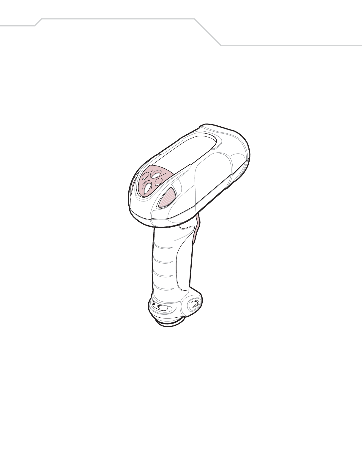
Figure 1-1. WLS 8400 Scanner
This scanner supports:
• Standard RS-232 connection to a host.
• Keyboard Wedge connection to a host, where scanned data is interpreted
keystrokes. The following international keyboards are supported (for Windows
TM
environment): North America, German, French, French Canadian, Spanish, Ita lian,
Swedish, UK English, Japanese, and Brazilian-Portuguese.
Page 24

WLS 8400 Product Reference Guide
1-4
• USB connection to a host. The scanner autodetects a USB host and defaults to the
HID keyboard interface type. Other USB interface types may be selected by
scanning programming bar codes. The following international keyboards are
supported (for Windows
™ environment): North America, German, French, French
Canadian, Spanish, Italian, Swedish, UK English, Japanese, and BrazilianPortuguese.
Unpacking the Scanner
Remove the scanner from its packing and inspect it for damage. If the scanner was damaged
in transit, call Wasp Support at one of the telephone numbers listed on page xvii. KEEP
THE P ACKING. It is the approved shipping container and should be used if the equipment
ever needs to be returned for servicing.
Page 25
Getting Started
1-5
Setting Up the Scanner
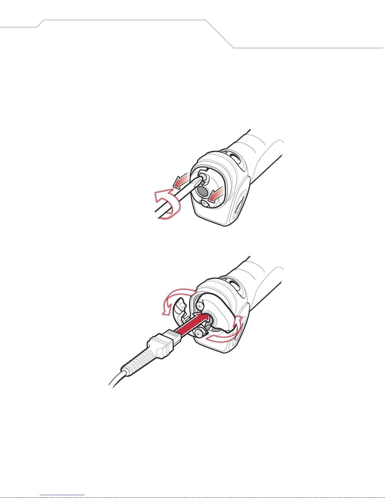
Installing the Interface Cable
1. Loosen the two screws on the cable clamp at the bottom of the scanner and gently
pull the clamp away from the bottom of the scanner.
2. Open the clamp and plug the interface cable modular connector into the cable
interface port on the bottom of the scanner handle.
3. Gently tug the cable to ensure the connector is properly secured.
Page 26
WLS 8400 Product Reference Guide
1-6
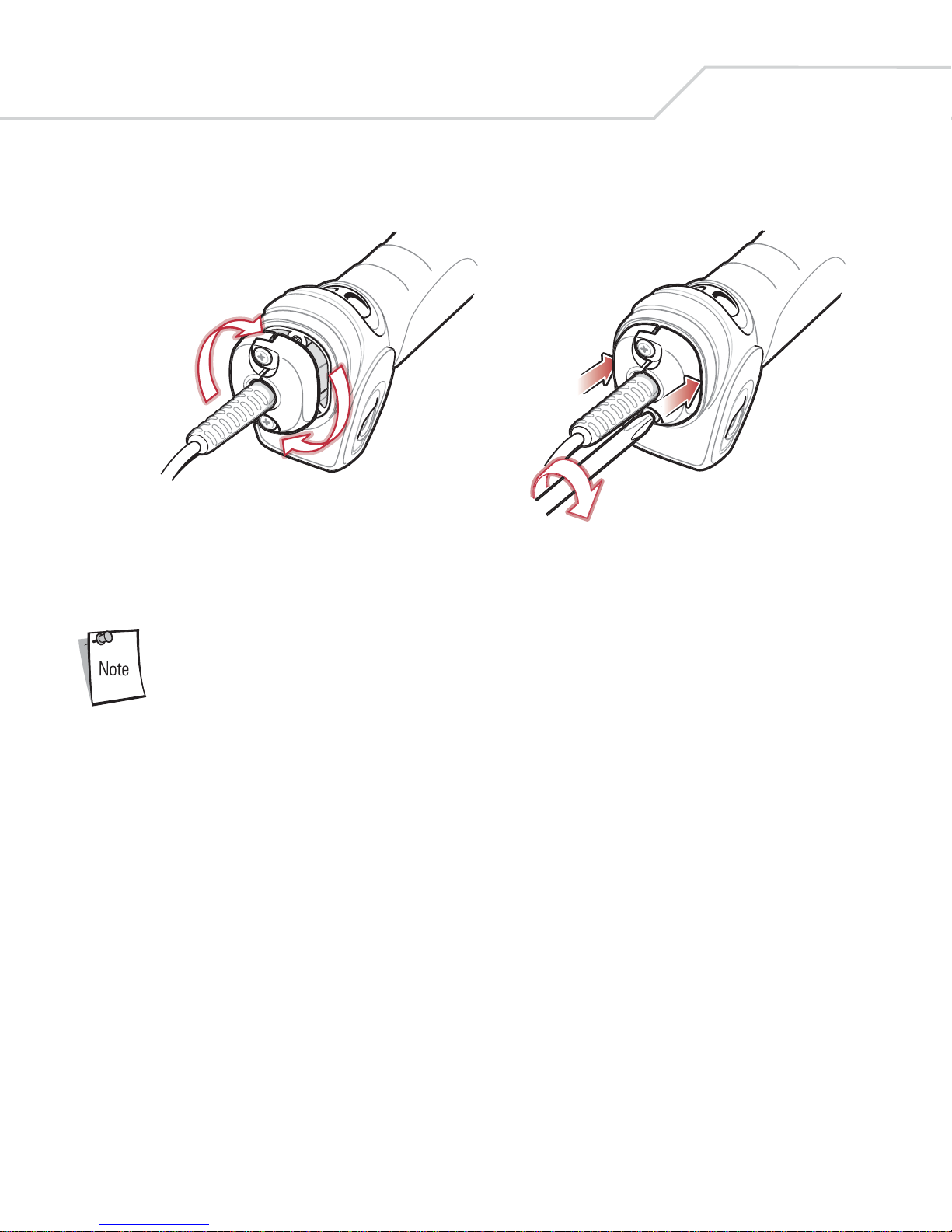
4. Close the clamp, push it back into place and tighten the screws on the clamp to
secure the cable into the bottom of the scanner.
5. Connect the other end of the interface cable to the host (see the specific host chapter
for information on host connections).
Different cables are required for different hosts. The connectors
illustrated in each host chapter are examples only. The connectors
may be different than those illustrated, but the steps to connect the
scanner remain the same.
Connecting Power (if required)
If the host does not provide power to the scanner, an external power connection is required
to power the scanner. To connect power:
1. Connect the interface cable to the bottom of the scanner, as described in Installing
the Interface Cable on page 1-5.
2. Connect the other end of the interface cable to the host (refer to the host manual to
locate the correct port).
3. Plug the power supply into the power jack on the interface cable. Plug the other end
of the power supply into an AC outlet.
Page 27

Getting Started
1-7
Removing the Interface Cable
1. Loosen the two screws on the cable clamp at the bottom of the scanner and gently
pull the clamp away from the bottom of the scanner.
2. Open the clamp and unplug the interface cable modular connector from the cable
interface port on the bottom of the scanner handle. Carefully slide out the cable.
3. Follow the steps for Installing the Interface Cable on page 1-5 to connect a new
cable.
Configuring the Scanner
Use the bar codes included in this manual to configure the scanner. See Chapter 4, User
Preferences and each host chapter for information about programming the scanner using
bar code menus.
Page 28

WLS 8400 Product Reference Guide
1-8
Page 29

2
Scanning
Introduction. . . . . . . . . . . . . . . . . . . . . . . . . . . . . . . . . . . . . . . . . . . . . . . . . . . . . . . . . . . . . . 2-3
Beeper Definitions. . . . . . . . . . . . . . . . . . . . . . . . . . . . . . . . . . . . . . . . . . . . . . . . . . . . . . . . . .2-4
LED Definitions . . . . . . . . . . . . . . . . . . . . . . . . . . . . . . . . . . . . . . . . . . . . . . . . . . . . . . . . . . .2-5
Scanning in Hand-Held Mode. . . . . . . . . . . . . . . . . . . . . . . . . . . . . . . . . . . . . . . . . . . . . . . . .2-6
Aiming . . . . . . . . . . . . . . . . . . . . . . . . . . . . . . . . . . . . . . . . . . . . . . . . . . . . . . . . . . . . . . .2-7
Scanning in Hands-Free Mode . . . . . . . . . . . . . . . . . . . . . . . . . . . . . . . . . . . . . . . . . . . . . . . .2-8
Decode Zone . . . . . . . . . . . . . . . . . . . . . . . . . . . . . . . . . . . . . . . . . . . . . . . . . . . . . . . . . . . . . .2-9
Page 30

WLS 8400 Product Reference Guide
2-2
Page 31

Scanning
2-3
Introduction
This chapter provides beeper and LED definitions, techniques involved in scanning bar
codes, general instructions and tips about scanning, and decode zone diagrams.
Figure 2-1. Parts
Scan Trigger
Scan
LED
Indicators
Tether Plate
Page 32

WLS 8400 Product Reference Guide
2-4
Beeper Definitions
The scanner emits different beeper sequences and patterns to indicate its status. Table 2-1
defines beep sequences that occur during both normal scanning and while programming the
scanner .
Table 2-1. Standard Beeper Definitions
Beeper Sequence Indication
Standard Use
Short low/short medium/short high
beep sequence
Power up.
1 short high beep A bar code symbol was decoded (if decode beeper is enabled).
4 long low beeps A transmission error was detected in a scanned symbol. The data is
ignored.
5 long low beeps Conversion or format error.
Short high/short high/short high/long
low beep sequence
RS-232 receive error .
Parameter Menu Scanning
Long low/long high beep sequence Incorrect programming sequence or ‘Cancel’ bar code scanned.
Scanner remains in program mode.
Short high/short low beep sequence Keyboard parameter selected. Enter value using bar code keypad.
Short high/short low/short high/short
low beep sequence
Successful program exit with change in the parameter setting.
Short low/short high/short low/short
high beep sequence
Out of host parameter storage space. Scan Set Default Parameter on
page 4-5.
USB only
4 short high beeps Scanner has not completed initialization. Wait several seconds and
scan again.
Short low/short medium/short high
beep sequence after scanning a USB
Device Type.
Communication with the bus must be established before the scanner
can operate at the highest power level.
Short low/short medium/short high
beep sequence occurs more than once.
The USB bus may put the scanner in a state where power to the
scanner is cycled on and off more than once. This is normal and
usually happens when the PC cold boots.
Page 33

Scanning
2-5
LED Definitions
In addition to beeper sequences, the scanner uses the two-color LED to indicate its status.
Table 2-2 defines LED colors that display during scanning.
RS-232 only
1 short high beep A <BEL> character is received and Beep on <BEL> is enabled.
Table 2-2. Standard LED Definitions
LED Indication
Off The scanner is on and ready to scan, or no power is applied to the
scanner.
Green A bar code was successfully decoded.
Red A data transmission error occurred.
Table 2-1. Standard Beeper Definitions (Continued)
Beeper Sequence Indication
Page 34

WLS 8400 Product Reference Guide
2-6
Scanning in Hand-Held Mode
Install and program the scanner (see Setting Up the Scanner on page 1-5). For assistance,
contact the local supplier or Wasp Support.
1. Ensure the scanner is properly connected to the host (see the appropriate host
chapter).
2. Aim the scanner at the bar code.
3. Press the scan trigger.
Figure 2-2. Scanning in Hand-Held Mode
4. Ensure the scan line crosses every bar and space of the symbol.
5. Upon successful decode, the scanner beeps, and the LED turns green. For more
information on beeper and LED definitions, see Table 2-1 and Table 2-2.
RIGHT
012345
WRONG
012345
Page 35

Scanning
2-7
Aiming
Do not hold the scanner directly over the bar code. Laser light reflecting directly back into
the scanner from the bar code is known as specular reflection. This specular reflection can
make decoding difficult.
The scanner can be tilted up to 65° forward or back and achieve a successful decode (Figure
2-3). Simple practice quickly shows what tolerances to work within.
Figure 2-3. Optimum Scan Angles
65°
65°
Page 36

WLS 8400 Product Reference Guide
2-8
Scanning in Hands-Free Mode
The optional IntelliStand adds greater flexibility to the scanning operation. When the
scanner is seated in the stand’s “cup,” the scanner’s built-in sensor places the scanner in
hands-free mode. When the scanner is removed from the stand it operates in its normal
hand-held mode.
Figure 2-4. Inserting the Scanner in the IntelliStand
To operate the scanner in the IntelliStand:
1. Ensure the scanner is properly connected to the host (see the appropriate host
chapter for information on host connections).
2. Insert the scanner into the IntelliStand by placing the front of the scanner into the
stand’s “cup” (see Figure 2-4).
3. To scan a bar code, present the bar code and ensure the scan line crosses every bar
and space of the symbol.
4. Upon successful decode, the scanner beeps and the LED turns green. For more
information on beeper and LED definitions, see Table 2-1 and Table 2-2.
Scanner “Cup”
Adjust height
of IntelliStand
Adjust angle of
scanner “cup”
Page 37

Scanning
2-9
Decode Zone
Figure 2-5. WLS 8400FZ Decode Zone
2.5"
7.25"
5 mil
2.0" 15.75"
7.5 mil
1.0" 24"
13 mil
100% UPC
0"*
39.5"
26.5"
20 mil (80%MRD)
20 mil (31%MRD)
40 mil
55 mil
2.0"*
4.0"*
67.0"
84.0"
0 1020304050607080
0 25.4 50.8 76.2 101.6 127.0 152.4 177.8 203.2
90
228.6
30
20
10
00
10
20
30
76.2
50.8
25.4
25.4
50.8
76.2
LS 3408
FZ
Note: Typical performance at 68˚F (20˚C)
on high quality Code 39 and UPC symbols.
*Minimum distance determined by symbol length and scan angle
Depth of Field
W
i
d
t
h
o
f
F
i
e
l
d
in.
cm
in. cm
Page 38

WLS 8400 Product Reference Guide
2-10
Figure 2-6. WLS 8400ER Decode Zone
15" 180"
55 mil
365"
70 mil reflective
*
540"
100 mil reflective
0 60 120 180 240 300 360 420 480 540 600
0 152.4 304.8 457.2 609.6 762.0 914.4 1066.8 1219.2 1371.6 1524.0
0
24
48
72
72
48
24
0
61.0
121.9
182.9
182.9
121.9
61.0
LS 3408
ER
Depth of Field
in.
cm
W
i
d
t
h
o
f
F
i
e
l
d
in. cm
Note: Typical performance at 73.4˚F (23˚C)
on high quality Code 39 symbols.
*Near range determined by degree of reflectivity and width of bar code.
0.25" 20"
7.5 mil
2" 32"
10 mil
3" 69"
15 mil
3" 94"
20 mil
0 102030405060708090 100
0 25.4 50.8 76.2 101.6 127.0 152.4 177.8 203.2 228.6 254.0
0
4
8
12
12
8
4
0
10.2
20.3
30.5
30.5
20.3
10.2
LS 3408
ER
Depth of Field
in.
cm
W
i
d
t
h
o
f
F
i
e
l
d
in. cm
Note: Typical performance at 73.4˚F (23˚C)
on high quality Code 39 symbols.
Page 39

3
Maintenance and Technical
Specifications
Introduction. . . . . . . . . . . . . . . . . . . . . . . . . . . . . . . . . . . . . . . . . . . . . . . . . . . . . . . . . . . . . . 3-3
Maintenance . . . . . . . . . . . . . . . . . . . . . . . . . . . . . . . . . . . . . . . . . . . . . . . . . . . . . . . . . . . . . .3-3
Troubleshooting . . . . . . . . . . . . . . . . . . . . . . . . . . . . . . . . . . . . . . . . . . . . . . . . . . . . . . . . . . .3-4
Technical Specifications . . . . . . . . . . . . . . . . . . . . . . . . . . . . . . . . . . . . . . . . . . . . . . . . . . . . .3-7
Scanner Signal Descriptions . . . . . . . . . . . . . . . . . . . . . . . . . . . . . . . . . . . . . . . . . . . . . . . . . .3-9
Page 40

WLS 8400 Product Reference Guide
3-2
Page 41

Maintenance and Technical Specifications
3-3
Introduction
This chapter provides suggested scanner maintenance, troubleshooting, technical
specifications, and signal descriptions (pinouts).
Maintenance
Cleaning the scan window is the only maintenance required. A dirty window may affect
scanning accuracy.
• Do not allow any abrasive material to touch the window.
• Remove any dirt particles with a damp cloth.
• Wipe the window using a tissue moistened with ammonia/water.
• Do not spray water or other cleaning liquids directly onto the window.
Page 42

WLS 8400 Product Reference Guide
3-4
Troubleshooting
Table 3-1. Troubleshooting
Problem Possible Causes Possible Solutions
Scanner emits short low/short
medium/short high beep sequence.
Scanner is powering up. Normal when scanner is plugged
in.
Nothing happens when scan trigger
is pressed.
No power to the scanner. Check the system power. Ensure
the power supply is connected if
the configuration requires a power
supply.
Power supply is not plugged in.
Incorrect host interface cable is
used.
Ensure that correct host interface
cable is used.
Interface/power cables are loose. Ensure all cable connections are
secure.
Scanner is disabled. For Simple Serial Interface (SSI),
enable the scanner via the host
interface. Otherwise, see the
technical person in charge of
scanning.
If using RS-232 Nixdorf B mode,
CTS is not asserted.
Assert CTS line.
Scanner emits short low/short
medium/short high beep sequence
more than once.
The USB bus may put the scanner
in a state where power to the
scanner is cycled on and off more
than once.
Normal during host reset.
Laser comes on, but scanner does
not decode the bar code.
Scanner is not programmed for the
correct bar code type.
Ensure the scanner is programmed
to read the type of bar code being
scanned.
Bar code symbol is unreadable. Check the symbol to ensure it is not
defaced. Try scanning test bar
codes of the same bar code type.
See Appendix C, Sample Bar Codes
for test bar codes.
Bar code is out of range from the
scanner.
Move scanner closer to or further
from bar code.
Page 43

Maintenance and Technical Specifications
3-5
Scanner emits 4 short high beeps
while attempting to scan.
Scanner has not completed USB
initialization.
Wait several seconds and scan
again.
Bar code is decoded, but data is not
transmitted to the host.
Scanner is not programmed for the
correct host type.
Scan the appropriate host
parameter bar codes.
Interface cable is loose. Ensure all cable connections are
secure.
If 4 long low beeps are heard, a
transmission error was detected.
Ensure the scanner's
communication parameters match
the host's setting.
If 5 long low beeps are heard, a
conversion or format error was
detected.
Ensure the scanner's conversion
parameters are properly
configured.
Scanned data is incorrectly
displayed on the host.
Scanner is not programmed to
work with the host.
Ensure proper host is selected.
For RS-232, ensure the scanner's
communication parameters match
the host's settings.
For a Keyboard Wedge
configuration, ensure the system is
programmed for the correct
keyboard type, and the CAPS
LOCK key is off.
Ensure editing options (e.g., UPCE to UPC-A conversion) are
properly programmed.
Scanner emits short high/short
high/short high/long low beep
sequence when it is not in use.
RS-232 receive error . Normal during host reset.
Otherwise, ensure the scanner's
RS-232 parity setting matches the
host setting.
Scanner emits long low/long high
beep sequence while it is being
programming.
Input error or ’Cancel’ bar code is
scanned.
Ensure the correct numeric bar
codes, that are within range for the
parameter that is being
programmed, are being scanned.
Scanner emits short low/short high/
short low/short high beep sequence
while it is being programming.
Out of ADF parameter storage
space.
Erase all rules and re-program with
shorter rules.
Table 3-1. Troubleshooting (Continued)
Problem Possible Causes Possible Solutions
Page 44

WLS 8400 Product Reference Guide
3-6
If after performing these checks the symbol still does not decode,
contact the distributor or call Wasp Support. See page xvii for the
telephone number.
Scanner emits a short low/short
medium/short high beep sequence
after changing USB host type.
The USB bus re-establishes power
to the scanner.
Normal when the USB host type is
changed.
Scanner emits 1 short high beep
when it is not in use.
In RS-232 mode, a <BEL>
character is received and Beep on
<BEL> option is enabled.
Normal when Beep on <BEL> is
enabled and the scanner is in RS232 mode.
Table 3-1. Troubleshooting (Continued)
Problem Possible Causes Possible Solutions
Page 45

Maintenance and Technical Specifications
3-7
Technical Specifications
Table 3-2. Technical Specifications
Item
Description
WLS 8400FZ WLS 8400ER
Power Requirements 4.5 - 14VDC
Stand-By Current 50mA (max)
Power Source Depending on host:
• host powered
• external power supply
Decode Capability UPC/EAN, Bookland EAN, UPC/EAN with supplementals, Code 128, UCC/
EAN 128, ISBT 128, Code 39, Trioptic Code 39, Code 93, Code 11, Interleaved
2 of 5, Discrete 2 of 5, Codabar (NW-7), MSI, RSS.
Beeper Operation User-selectable: Enable, Disable
Beeper Volume User-selectable: Three levels
Beeper Tone User-selectable: Three tones
Scan Repetition Rate 36 scans/second
Yaw Tolerance ± 50° from nominal ± 60° from nominal
Pitch Tolerance ± 65° from nominal ± 65° from nominal
Roll Tolerance ± 20° from nominal ± 10° from nominal
Print Contrast Minimum 25% minimum reflectance differential, measured at 650 nm.
Ambient Light Immunity
Indoor:
Outdoor:
450 Ft Candles (4,842 Lux)
8,000 Ft Candles (86,080 Lux)
450 Ft Candles (4,842 Lux)
4,000 Ft Candles (43,040 Lux)
Durability 6.5 ft (2.0 m) drops to concrete
Operating Temperature -22° to 122° F (-30° to 50° C)
Storage Temperature -40° to 158° F (-40° to 70° C)
Humidity 5% to 95% (non-condensing)
Weight (without cable) 12.35 oz. (350 g) 12.56 oz. (356 g)
Page 46

WLS 8400 Product Reference Guide
3-8
Dimensions:
Height
Width
Depth
7.34 in. (18.65 cm)
4.82 in. (12.25 cm)
2.93 in. (7.43 cm)
Laser 650nm laser diode
Laser Classifications IEC 825-1 Class 2
ESD 20 kV area discharge
8 kV contact discharge
Minimum Element Width 5 mil (0.127 mm) 7.5 mil (0.191 mm)
Interfaces Supported Keyboard Wedge, RS-232, USB
Electrical Safety Certified Pending to UL1950, CSA C22.2 No.950. EN60950/IC950
Input Transient
Protection
IEC 1000-4-(2,3,4,5,6,11)
EMI FCC Part 15 Class B, ICES-003 Class B European Union EMC Directive,
Australian SMA, T a iwan EMC, Japan VCCI/MITI/Dentori
Table 3-2. Technical Specifications (Continued)
Item
Description
WLS 8400FZ WLS 8400ER
Page 47

Maintenance and Technical Specifications
3-9
Scanner Signal Descriptions
Figure 3-1. Scanner Cable Pinouts
Cable interface port
Interface cable
modular
Bottom of
PIN 1PIN 10
Page 48

WLS 8400 Product Reference Guide
3-10
The signal descriptions in Table 3-3 apply to the connector on the scanner and are for
reference only.
Table 3-3. Scanner Signal Pin-outs
Pin RS-232
Keyboard
Wedge USB
1 Reserved Reserved Jump to Pin 6
2 Power Power Power
3 Ground Ground Ground
4 TxD KeyClock Reserved
5 RxD TermData D +
6 RTS KeyData Jump to Pin 1
7 CTS TermClock D -
8 Reserved Reserved Reserved
9 Reserved Reserved Reserved
10 Reserved Reserved Reserved
Page 49

4
User Preferences
Introduction. . . . . . . . . . . . . . . . . . . . . . . . . . . . . . . . . . . . . . . . . . . . . . . . . . . . . . . . . . . . . . 4-3
Scanning Sequence Examples. . . . . . . . . . . . . . . . . . . . . . . . . . . . . . . . . . . . . . . . . . . . . . . . .4-3
Errors While Scanning . . . . . . . . . . . . . . . . . . . . . . . . . . . . . . . . . . . . . . . . . . . . . . . . . . . . . .4-3
User Preferences Default Parameters . . . . . . . . . . . . . . . . . . . . . . . . . . . . . . . . . . . . . . . . . . .4-4
User Preferences . . . . . . . . . . . . . . . . . . . . . . . . . . . . . . . . . . . . . . . . . . . . . . . . . . . . . . . . . . .4-5
Set Default Parameter . . . . . . . . . . . . . . . . . . . . . . . . . . . . . . . . . . . . . . . . . . . . . . . . . . .4-5
Beeper Tone. . . . . . . . . . . . . . . . . . . . . . . . . . . . . . . . . . . . . . . . . . . . . . . . . . . . . . . . . . .4-5
Beeper Volume . . . . . . . . . . . . . . . . . . . . . . . . . . . . . . . . . . . . . . . . . . . . . . . . . . . . . . . .4-6
Power Mode. . . . . . . . . . . . . . . . . . . . . . . . . . . . . . . . . . . . . . . . . . . . . . . . . . . . . . . . . . .4-7
Laser On Time- . . . . . . . . . . . . . . . . . . . . . . . . . . . . . . . . . . . . . . . . . . . . . . . . . . . . . . . .4-7
Beep After Good Decode. . . . . . . . . . . . . . . . . . . . . . . . . . . . . . . . . . . . . . . . . . . . . . . . .4-8
Trigger Mode . . . . . . . . . . . . . . . . . . . . . . . . . . . . . . . . . . . . . . . . . . . . . . . . . . . . . . . . . .4-8
Aim Duration . . . . . . . . . . . . . . . . . . . . . . . . . . . . . . . . . . . . . . . . . . . . . . . . . . . . . . . . .4-10
Page 50

WLS 8400 Product Reference Guide
4-2
Page 51

User Preferences
4-3
Introduction
The scanner can be programed to perform various functions, or activate different features.
This chapter describes each user preference feature and provides the programming bar
codes necessary for selecting these features for the scanner.
The scanner ships with the settings shown in the User Preferences Default Table on page
4-4 (also see Chapter A, Standar d Default Parameters for all host device and miscellaneous
scanner defaults). If the default values suit the requirements, programming may not be
necessary.
Feature values are set by scanning single bar codes or short bar code sequences. The
settings are stored in non-volatile memory and are preserved even when the scanner is
powered down.
If the USB cable is not being used, selec t a host type (see each host chapter for specific host
information). After hearing the power-up beeps, select a host type. This only needs to be
done once, upon the first power-up when connected to a new host.
To return all features to their default values, scan the Set All Defaults bar code on page 4-
5. Throughout the programming bar code menus, default values are indicated with asterisks
(
*).
Scanning Sequence Examples
In most cases, only one bar code needs to be scanned to set a specific parameter value. For
example, to set the beeper tone to high, simply scan the High Frequency (beeper tone) bar
code listed under Beeper Tone on page 4-5. The scanner issues a fast warble beep and the
LED turns green, signifying a successful parameter entry.
Other parameters, such as specifying Laser On Time or setting Data Transmission
Formats, require that several bar codes be scanned. See Laser On Time on page 4-7 and
Scan Data Transmission Format on page 9-7 for descriptions of this procedure.
Errors While Scanning
Unless otherwise specified, if an error is made during a scanning sequence, just re-scan the
correct parameter.
*High Frequency
Feature/Option
* Indicates Default
Page 52

WLS 8400 Product Reference Guide
4-4
User Preferences Default Parameters
T able 4-1 lists the defaults for user preferences parameters. To change any option, scan the
appropriate bar code(s) provided in the User Preferences section beginning on page 4-5.
See Chapter A, Standar d Default Parameters for all user preferences,
hosts, symbologies, and miscellaneous default parameters.
Table 4-1. User Preferences Default Table
Parameter Default Page Number
User Preferences
Set Default Parameter All Defaults 4-5
Beeper Tone High 4-5
Beeper Volume High 4-6
Power Mode Continuous On 4-7
Laser On Time 3.0 sec 4-7
Beep After Good Decode Enable 4-8
Trigger Mode Level 4-8
Aim Duration 0.0 sec 4-10
Page 53

User Preferences
4-5
User Preferences
Set Default Parameter
Scanning this bar code returns all parameters to the default values listed in Table A-1 on
page A-3.
Set All Defaults
Beeper Tone
T o select a decode beep frequency (tone), scan the Low Frequency, Medium Frequency,
or High Frequency bar code.
Low Frequency
Medium Frequency
*High Frequency
Page 54

WLS 8400 Product Reference Guide
4-6
Beeper Volume
To select a beeper volume, scan the Low Volume, Medium Volume, or High Volume bar
code.
Low Volume
Medium Volume
*High Volume
Page 55

User Preferences
4-7
Power Mode
This parameter determines whether or not the scanner enters reduced power mode after a
decode attempt. When in reduced power mode, the scanner draws less current from its
power source.
*Continuous On
Reduced Power Mode
Laser On Time
This parameter sets the maximum time that decode processing continues during a scan
attempt. It is programmable in 0.1 second increments from 0.5 to 9.9 seconds. The default
Laser On Time is 3.0 seconds.
To set a Laser On Time, scan the bar code below. Next, scan two numeric bar codes
beginning on page D-1 in Chapter D, Numeric Bar Codes that correspond to the desired on
time. Single digit numbers must have a leading zero. For example, to set a Laser On Time
of 0.5 seconds, scan the bar code below, then scan the “0” and “5” bar codes. In case of an
error, or to change the selection, scan Cancel on page D-7.
Laser On Time
Page 56

WLS 8400 Product Reference Guide
4-8
Beep After Good Decode
Scan a bar code below to select whether or not the scanner beeps after a good decode. If Do
Not Beep After Good Decode is selected, the beeper still operates during parameter menu
scanning and indicates error conditions.
*Beep After Good Decode
(Enable)
Do Not Beep After Good Decode
(Disable)
Trigger Mode
The scanner has three trigger modes that can be used to scan bar codes. The desired trigger
mode can be set by using the bar codes below.
Level Trigger
When the trigger is pulled, an aiming dot appears for a programmable duration of time.
After this time, the aiming dot automatically turns into a standard laser scanning beam for
a full decode session. The laser scanning beam stays on until the laser -on timeout occurs, a
decode occurs, or the trigger is released. If the trigger is released before the aiming duration
expires, the laser shuts off and no decode occurs.
*Level
Page 57

User Preferences
4-9
Trigger Mode (continued)
Two Stage - Option 1
When the trigger is pulled, an aiming dot appears. This aiming dot remains while the trigger
is pulled. When the trigger is released, the aiming dot automatically turns into a standard
laser scanning beam for a full decode session. The laser scanning beam stays on until the
laser-on timeout occurs or a decode occurs. If the trigger is pulled again while in a decode
session, the scanner beam returns to an aiming dot.
Two Stage - Option 1
Two Stage - Option 2
When the trigger is pulled, an aiming dot appears. When the trigger is released, the aiming
dot turns off. Pulling the trigger twice in rapid succession turns on the standard laser
scanning beam for a full decode session. The laser scanning beam, stays on until the laseron timeout occurs, a decode occurs, or the trigger is released.
Two Stage - Option 2
Page 58

WLS 8400 Product Reference Guide
4-10
Aim Duration
When the scanner is in Level trigger mode (default mode), Aim Duration sets the amount
of time the aiming dot is seen before turning into a scanning beam. This parameter has no
affect when the scanner is in either of the Two Stage trigger modes. See Trigger Mode on
page 4-8 for a description of each of the trigger modes.
The aim duration is programmable in 0.1 second increments, from 0.0 to 9.9 seconds. The
default Aim Duration is 0.0 seconds. When set to 0.0 seconds, no aiming pattern appears
before a decode session.
To set an aim duration, scan the bar code below. Then scan two numeric bar codes,
available in Appendix D, Numeric Bar Codes, that correspond to the desired aim duration.
Durations less than 1.0 seconds must have a leading zero. For example, to set an aim
duration of 0.5 seconds, scan the bar code below , followed by the ‘0’ and the ‘5’ bar codes.
In case of an error, or to change the selection, scan the ‘Cancel’ bar code on page D-7.
Aim Duration
Page 59

5
Keyboard Wedge Interface
Introduction. . . . . . . . . . . . . . . . . . . . . . . . . . . . . . . . . . . . . . . . . . . . . . . . . . . . . . . . . . . . . . 5-3
Connecting a Keyboard Wedge Interface . . . . . . . . . . . . . . . . . . . . . . . . . . . . . . . . . . . . . . . .5-4
Keyboard Wedge Default Parameters. . . . . . . . . . . . . . . . . . . . . . . . . . . . . . . . . . . . . . . . . . .5-5
Keyboard Wedge Host Types . . . . . . . . . . . . . . . . . . . . . . . . . . . . . . . . . . . . . . . . . . . . . . . . .5-6
Keyboard Wedge Host Types . . . . . . . . . . . . . . . . . . . . . . . . . . . . . . . . . . . . . . . . . . . . .5-6
Keyboard Wedge Country Types (Country Codes). . . . . . . . . . . . . . . . . . . . . . . . . . . . .5-7
Ignore Unknown Characters . . . . . . . . . . . . . . . . . . . . . . . . . . . . . . . . . . . . . . . . . . . . . .5-9
Keystroke Delay. . . . . . . . . . . . . . . . . . . . . . . . . . . . . . . . . . . . . . . . . . . . . . . . . . . . . . . .5-9
Intra-Keystroke Delay . . . . . . . . . . . . . . . . . . . . . . . . . . . . . . . . . . . . . . . . . . . . . . . . . .5-10
Alternate Numeric Keypad Emulation. . . . . . . . . . . . . . . . . . . . . . . . . . . . . . . . . . . . . .5-11
Caps Lock On. . . . . . . . . . . . . . . . . . . . . . . . . . . . . . . . . . . . . . . . . . . . . . . . . . . . . . . . .5-11
Caps Lock Override . . . . . . . . . . . . . . . . . . . . . . . . . . . . . . . . . . . . . . . . . . . . . . . . . . . .5-12
Convert Wedge Data . . . . . . . . . . . . . . . . . . . . . . . . . . . . . . . . . . . . . . . . . . . . . . . . . . .5-13
Function Key Mapping . . . . . . . . . . . . . . . . . . . . . . . . . . . . . . . . . . . . . . . . . . . . . . . . .5-13
FN1 Substitution . . . . . . . . . . . . . . . . . . . . . . . . . . . . . . . . . . . . . . . . . . . . . . . . . . . . . .5-14
Send Make and Break . . . . . . . . . . . . . . . . . . . . . . . . . . . . . . . . . . . . . . . . . . . . . . . . . .5-14
Page 60

WLS 8400 Product Reference Guide
5-2
Keyboard Maps. . . . . . . . . . . . . . . . . . . . . . . . . . . . . . . . . . . . . . . . . . . . . . . . . . . . . . . 5-15
ASCII Character Set. . . . . . . . . . . . . . . . . . . . . . . . . . . . . . . . . . . . . . . . . . . . . . . . . . . . . . . 5-18
Page 61

Keyboard Wedge Interface
5-3
Introduction
This chapter provides Keyboard Wedge interface information for setting up the scanner.
This interface type is used to attach the scanner between the keyboard and host computer.
The scanner translates the bar code data into keystrokes. The host computer accepts the
keystrokes as if they originate from the keyboard.
This mode of operation allows adding bar code reading functionalit y to a system designed
for manual keyboard input. In this mode, the keyboard keystrokes are simply passed
through.
Throughout the programming bar code menus, default values are indicated with asterisks
(
*).
*North American
Feature/Option
* Indicates Default
Page 62

WLS 8400 Product Reference Guide
5-4
Connecting a Keyboard Wedge Interface
Figure 5-1. Keyboard Wedge Interface Connection with Y-cable
To connect the keyboard wedge interface Y-cable:
Interface cables vary depending on configuration. The connectors
illustrated in Figure 5-1 are examples only. The connectors may be
different than those illustrated, but the steps to connect the scanner
remain the same.
1. Turn off the host and unplug the keyboard connector.
2. Attach the modular connector of the Y-cable to the cable interface port on the
scanner. (See Installing the Interface Cable on page 1-5.)
3. Connect the round male DIN host connector of the Y-cable to the keyboard port on
the host.
4. Connect the round female DIN keyboard connector of the Y-cable to the keyboard
connector.
5. If required, attach the optional power supply to the connector in the middle of the
Y-cable.
6. Ensure that all connections are secure.
Y-cable
Male DIN Host
Female DIN Keyboard Keyboard
Page 63

Keyboard Wedge Interface
5-5
7. Turn on the host system.
8. Select the Keyboard Wedge host type by scanning the appropriate bar code from
the Keyboard Wedg e Host Types section on page 5-7.
9. To modify any other parameter options, scan the appropriate bar codes in this
chapter.
Keyboard Wedge Default Parameters
Table 5-1 lists the defaults for Keyboard Wedge host parameters. To change any option,
scan the appropriate bar code(s) provided in the Keyboard W edge Host Parameters section
beginning on page 5-7.
See Chapter A, Standar d Default Parameters for all user preferences,
hosts, symbologies, and miscellaneous default parameters.
Table 5-1. Keyboard Wedge Host Default Table
Parameter Default Page Number
Keyboard Wedge Host Parameters
Keyboard Wedge Host T ype IBM PC/AT& IBM PC Compatibles 5-7
Keyboard Wedge Country Types (Country
Codes)
North American 5-8
Ignore Unknown Characters Enable 5-10
Keystroke Delay 0 msec (No Delay) 5-10
Intra-Keystroke Delay Disable 5-11
Alternate Numeric Keypad Emulation Disable 5-12
Caps Lock On Disable 5-12
Caps Lock Override Disable 5-13
Convert Wedge Data Do Not Convert Wedge Data 5-14
Function Key Mapping Disable 5-15
Page 64

WLS 8400 Product Reference Guide
5-6
FN1 Substitution Disable 5-15
Send Make and Break Send Make and Break Scan Codes 5-15
Table 5-1. Keyboard Wedge Host Default Table (Continued)
Parameter Default Page Number
Page 65

Keyboard Wedge Interface
5-7
Keyboard Wedge Host Types
Keyboard Wedge Host Types
Select the keyboard wedge host by scanning one of the bar codes below.
*IBM PC/AT & IBM PC Compatibles
IBM PS/2 (Model 30)
IBM AT NOTEBOOK
IBM XT
NCR 7052
Page 66

WLS 8400 Product Reference Guide
5-8
Keyboard Wedge Country Types (Country Codes)
Scan the bar code corresponding to the keyboard type. If the particular keyboard type is not
listed, see Alternate Numeric Keypad Emulation on page 5-12.
*North American
German Windows
French Windows
French Canadian Windows 95/98
French Canadian Windows XP/2000
Page 67

Keyboard Wedge Interface
5-9
Keyboard Wedge Country Types (Country Codes) (continued)
Spanish Windows
Italian Windows
Swedish Windows
UK English Windows
Japanese Windows
Brazilian-Portuguese Windows
Page 68

WLS 8400 Product Reference Guide
5-10
Ignore Unknown Characters
Unknown characters are characters the host does not recognize. When Send Bar Codes
With Unknown Characters is selected, all bar code data is sent except for unknown
characters, and no error beeps sound on the scanner. When Do Not Send Bar Codes W ith
Unknown Characters is selected, bar code data is sent up to the first unknown character
and then an error beep sounds on the scanner.
*Send Bar Codes with Unknown Characters
(Enable)
Do Not Send Bar Codes with Unknown Characters
(Disable)
Keystroke Delay
This is the delay in milliseconds between emulated keystrokes. Scan a bar code below to
increase the delay when hosts require a slower transmission of data.
*0 msec (No Delay)
20 msec (Medium Delay)
Page 69

Keyboard Wedge Interface
5-11
Keystroke Delay (continued)
40 msec (Long Delay)
Intra-Keystroke Delay
When enabled, an additional delay is inserted between each emulated key depression and
release. This sets the Keystroke Delay parameter to a minimum of 5 msec, as well.
Enable Intra-Keystroke Delay
*Disable Intra-Keystroke Delay
Page 70

WLS 8400 Product Reference Guide
5-12
Alternate Numeric Keypad Emulation
This allows emulation of most other country keyboard types not listed in Keyboard Wedge
Country Types (Country Codes) on page 5-8 in a Microsoft
®
operating system
environment.
Enable Alternate Numeric Keypad
*Disable Alternate Numeric Keypad
Caps Lock On
When enabled, the scanner emulates keystrokes as if the Caps Lock key is always pressed.
Enable Caps Lock On
*Disable Caps Lock On
Page 71

Keyboard Wedge Interface
5-13
Caps Lock Override
When enabled, on AT or AT Notebook hosts, the keyboard ignores the state of the Caps
Lock key . Therefore, an ‘A’ in the bar code is sent as an ‘A’ no matter what the state of the
keyboard’s Caps Lock key.
Enable Caps Lock Override
*Disable Caps Lock Override
If both Caps Lock On and Caps Lock Override are enabled, Caps
Lock Override takes precedence.
Page 72

WLS 8400 Product Reference Guide
5-14
Convert Wedge Data
When enabled, the scanner converts all bar code data to the selected case.
Convert Wedge Data to Upper Case
Convert We dge Data to Lower Case
*Do Not Convert Wedge Data
Function Key Mapping
ASCII values under 32 are normally sent as control key sequences (see Table 5-2 on page
5-19). When this parameter is enabled, the keys in bold are sent in place of the standard key
mapping. Table entries that do not have a bold entry remain the same whether or not this
parameter is enabled.
Enable Function Key Mapping
*Disable Function Key Mapping
Page 73

Keyboard Wedge Interface
5-15
FN1 Substitution
When enabled, this parameter allows replacement of any FN1 characters in an EAN128 b ar
code with a keystroke chosen by the user. (see FN1 Substitution Values on page 9-9).
Enable FN1 Substitution
*Disable FN1 Substitution
Send Make and Break
When enabled, the scan codes for releasing a key are not sent.
*Send Make and Break Scan Codes
Send Make Scan Code Only
Page 74

WLS 8400 Product Reference Guide
5-16
Keyboard Maps
The following keyboard maps are provided for prefix/suffix keystroke parameters. To
program the prefix/suffix values, see the bar codes on page 9-6.
Figure 5-2. IBM PS2 Type Keyboard
Figure 5-3. IBM PC/XT
7013
7014 5001 5002 5003 5004 5005 5006 5007 5008 5009 5010
7013
5011
7010 7007
7006
7001
5012
7008
7009
7011
7012
7003
7002 7004 7005
7017 7016
7015
7018
5001
5002
5003
5004
5005
5006
5007
5008
5009
5010
7009
7014
7008
7013
7012
7004
7011 7002
7003
7006
Page 75

Keyboard Wedge Interface
5-17
Figure 5-4. IBM PC/AT
Figure 5-5. NCR 7052 32-KEY
5001
5002
5003
5004
5005
5006
5007
5008
5009
5010
7009
7008
7013
7012
7004
7011
7003
7002
7014
5007
5008
5010
5002
5003
5004
5005 5006
1046
1045
5014
1043
5013
5015
5016
5018
5019
5001
5017
7013
5011
(7013 if double key)
(1048 if double key)
1048
5012
5009
Page 76

WLS 8400 Product Reference Guide
5-18
Figure 5-6. NCR 7052 58-KEY
5007
5008
5010
5002
5003
5004
5005 5006
1046
1045
5014
1043
5013
5015
5016
5018
5019
1086
1087
1088
1089
1090
5001
1066
1072
1073
1079 1080
1065
1070
1076
1077
1083 1084
1071
1078
1085
1069
5017
7013
5011
1082
1075
1068
1067
(1043 if double key)
(1048 if double key)
1048
5012
5009
1074
1081
Page 77

Keyboard Wedge Interface
5-19
ASCII Character Set
Code 39 Full ASCII interprets the bar code special character
($ + % /) preceding a Code 39 character and assigns an ASCII
character value to the pair. For example, when Code 39 Full ASCII is
enabled and a +B is scanned, it is interpreted as b, %J as ?, and %V
as @. Scanning ABC%I outputs the keys troke equivalent of ABC >.
Table 5-2. Keyboard Wedge ASCII Character Set
ASCII Value
Full ASCII
Code 39
Encode Character Keystroke
1001 $A CTRL A
1002 $B CTRL B
1003 $C CTRL C
1004 $D CTRL D
1005 $E CTRL E
1006 $F CTRL F
1007 $G CTRL G
1008 $H CTRL H/
BACKSPACE
1
1009 $I CTRL I/
HORIZONTAL TAB
1
1010 $J CTRL J
1011 $K CTRL K
1012 $L CTRL L
1013 $M CTRL M/ENTER
1
1014 $N CTRL N
1015 $O CTRL O
1016 $P CTRL P
1017 $Q CTRL Q
1
The keystroke in bold is sent only if the “Function Key Mapping” is enabled.
Otherwise, the unbolded keystroke is sent.
Page 78

WLS 8400 Product Reference Guide
5-20
1018 $R CTRL R
1019 $S CTRL S
1020 $T CTRL T
1021 $U CTRL U
1022 $V CTRL V
1023 $W CTRL W
1024 $X CTRL X
1025 $Y CTRL Y
1026 $Z CTRL Z
1027 %A CTRL [ /ESC
1
1028 %B CTRL \
1029 %C CTRL ]
1030 %D CTRL 6
1031 %E CTRL 1032 Space Space
1033 /A !
1034 /B “
1035 /C #
1036 /D $
1037 /E %
1038 /F &
1039 /G ‘
1040 /H (
1041 /I )
Table 5-2. Keyboard Wedge ASCII Character Set (Continued)
ASCII Value
Full ASCII
Code 39
Encode Character Keystroke
1
The keystroke in bold is sent only if the “Function Key Mapping” is enabled.
Otherwise, the unbolded keystroke is sent.
Page 79

Keyboard Wedge Interface
5-21
1042 /J *
1043 /K +
1044 /L ,
1045 - 1046 . .
1047 /O /
1048 0 0
1049 1 1
1050 2 2
1051 3 3
1052 4 4
1053 5 5
1054 6 6
1055 7 7
1056 8 8
1057 9 9
1058 /Z :
1059 %F ;
1060 %G <
1061 %H =
1062 %I >
1063 %J ?
1064 %V @
1065 A A
Table 5-2. Keyboard Wedge ASCII Character Set (Continued)
ASCII Value
Full ASCII
Code 39
Encode Character Keystroke
1
The keystroke in bold is sent only if the “Function Key Mapping” is enabled.
Otherwise, the unbolded keystroke is sent.
Page 80

WLS 8400 Product Reference Guide
5-22
1066 B B
1067 C C
1068 D D
1069 E E
1070 F F
1071 G G
1072 H H
1073 I I
1074 J J
1075 K K
1076 L L
1077 M M
1078 N N
1079 O O
1080 P P
1081 Q Q
1082 R R
1083 S S
1084 T T
1085 U U
1086 V V
1087 W W
1088 X X
1089 Y Y
Table 5-2. Keyboard Wedge ASCII Character Set (Continued)
ASCII Value
Full ASCII
Code 39
Encode Character Keystroke
1
The keystroke in bold is sent only if the “Function Key Mapping” is enabled.
Otherwise, the unbolded keystroke is sent.
Page 81

Keyboard Wedge Interface
5-23
1090 Z Z
1091 %K [
1092 %L \
1093 %M ]
1094 %N ^
1095 %O _
1096 %W ‘
1097 +A a
1098 +B b
1099 +C c
1100 +D d
1101 +E e
1102 +F f
1103 +G g
1104 +H h
1105 +I i
1106 +J j
1107 +K k
1108 +L l
1109 +M m
1110 +N n
1111 +O o
1112 +P p
1113 +Q q
Table 5-2. Keyboard Wedge ASCII Character Set (Continued)
ASCII Value
Full ASCII
Code 39
Encode Character Keystroke
1
The keystroke in bold is sent only if the “Function Key Mapping” is enabled.
Otherwise, the unbolded keystroke is sent.
Page 82

WLS 8400 Product Reference Guide
5-24
1114 +R r
1115 +S s
1116 +T t
1117 +U u
1118 +V v
1119 +W w
1120 +X x
1121 +Y y
1122 +Z z
1123 %P {
1124 %Q |
1125 %R }
1126 %S ~
Table 5-2. Keyboard Wedge ASCII Character Set (Continued)
ASCII Value
Full ASCII
Code 39
Encode Character Keystroke
1
The keystroke in bold is sent only if the “Function Key Mapping” is enabled.
Otherwise, the unbolded keystroke is sent.
Page 83

Keyboard Wedge Interface
5-25
Table 5-3. Keyboard Wedge ALT Key Character Set
ALT Keys Keystroke
2065 ALT A
2066 ALT B
2067 ALT C
2068 ALT D
2069 ALT E
2070 ALT F
2071 ALT G
2072 ALT H
2073 ALT I
2074 ALT J
2075 ALT K
2076 ALT L
2077 ALT M
2078 ALT N
2079 ALT O
2080 ALT P
2081 ALT Q
2082 ALT R
2083 ALT S
2084 ALT T
2085 ALT U
2086 ALT V
2087 ALT W
2088 ALT X
2089 ALT Y
2090 ALT Z
Page 84

WLS 8400 Product Reference Guide
5-26
Table 5-4. Keyboard Wedge GUI Key Character Set
GUI Keys Keystrokes
3000 Right Control Key
3048 GUI 0
3049 GUI 1
3050 GUI 2
3051 GUI 3
3052 GUI 4
3053 GUI 5
3054 GUI 6
3055 GUI 7
3056 GUI 8
3057 GUI 9
3065 GUI A
3066 GUI B
3067 GUI C
3068 GUI D
3069 GUI E
3070 GUI F
3071 GUI G
3072 GUI H
3073 GUI I
3074 GUI J
3075 GUI K
3076 GUI L
3077 GUI M
3078 GUI N
3079 GUI O
3080 GUI P
Page 85

Keyboard Wedge Interface
5-27
3081 GUI Q
3082 GUI R
3083 GUI S
3084 GUI T
3085 GUI U
3086 GUI V
3087 GUI W
3088 GUI X
3089 GUI Y
3090 GUI Z
Table 5-5. Keyboard Wedge F Key Character Set
F Keys Keystroke
5001 F1
5002 F2
5003 F3
5004 F4
5005 F5
5006 F6
5007 F7
5008 F8
5009 F9
5010 F10
5011 F11
5012 F12
Table 5-4. Keyboard Wedge GUI Key Character Set (Continued)
GUI Keys Keystrokes
Page 86

WLS 8400 Product Reference Guide
5-28
5013 F13
5014 F14
5015 F15
5016 F16
5017 F17
5018 F18
5019 F19
5020 F20
5021 F21
5022 F22
5023 F23
5024 F24
Table 5-6. Keyboard Wedge Numeric Keypad Character Set
Numeric Keypad Keystroke
6042 *
6043 +
6044 undefined
6045 6046 .
6047 /
6048 0
6049 1
6050 2
6051 3
Table 5-5. Keyboard Wedge F Key Character Set (Continued)
F Keys Keystroke
Page 87

Keyboard Wedge Interface
5-29
6052 4
6053 5
6054 6
6055 7
6056 8
6057 9
6058 Enter
6059 Num Lock
Table 5-7. Keyboard Wedge Extended Keypad Character Set
Extended Keypad Keystroke
7001 Break
7002 Delete
7003 Pg Up
7004 End
7005 Pg Dn
7006 Pause
7007 Scroll Lock
7008 Backspace
7009 Tab
7010 Print Screen
7011 Insert
7012 Home
7013 Enter
7014 Escape
Table 5-6. Keyboard Wedge Numeric Keypad Character Set (Continued)
Numeric Keypad Keystroke
Page 88

WLS 8400 Product Reference Guide
5-30
7015 Up Arrow
7016 Dn Arrow
7017 Left Arrow
7018 Right Arrow
Table 5-7. Keyboard Wedge Extended Keypad Character Set (Continued)
Extended Keypad Keystroke
Page 89

6
RS-232 Interface
Introduction. . . . . . . . . . . . . . . . . . . . . . . . . . . . . . . . . . . . . . . . . . . . . . . . . . . . . . . . . . . . . . 6-3
Connecting an RS-232 Interface. . . . . . . . . . . . . . . . . . . . . . . . . . . . . . . . . . . . . . . . . . . . . . .6-4
RS-232 Default Parameters. . . . . . . . . . . . . . . . . . . . . . . . . . . . . . . . . . . . . . . . . . . . . . . . . . .6-5
RS-232 Host Parameters . . . . . . . . . . . . . . . . . . . . . . . . . . . . . . . . . . . . . . . . . . . . . . . . . . . . .6-6
RS-232 Host Types . . . . . . . . . . . . . . . . . . . . . . . . . . . . . . . . . . . . . . . . . . . . . . . . . . . . .6-8
Baud Rate. . . . . . . . . . . . . . . . . . . . . . . . . . . . . . . . . . . . . . . . . . . . . . . . . . . . . . . . . . . . .6-9
Parity . . . . . . . . . . . . . . . . . . . . . . . . . . . . . . . . . . . . . . . . . . . . . . . . . . . . . . . . . . . . . . .6-11
Check Receive Errors. . . . . . . . . . . . . . . . . . . . . . . . . . . . . . . . . . . . . . . . . . . . . . . . . . .6-12
Stop Bit Select . . . . . . . . . . . . . . . . . . . . . . . . . . . . . . . . . . . . . . . . . . . . . . . . . . . . . . . .6-13
Data Bits. . . . . . . . . . . . . . . . . . . . . . . . . . . . . . . . . . . . . . . . . . . . . . . . . . . . . . . . . . . . .6-13
Hardware Handshaking . . . . . . . . . . . . . . . . . . . . . . . . . . . . . . . . . . . . . . . . . . . . . . . . .6-14
Software Handshaking. . . . . . . . . . . . . . . . . . . . . . . . . . . . . . . . . . . . . . . . . . . . . . . . . .6-17
Host Serial Response Time-out . . . . . . . . . . . . . . . . . . . . . . . . . . . . . . . . . . . . . . . . . . .6-19
RTS Line State. . . . . . . . . . . . . . . . . . . . . . . . . . . . . . . . . . . . . . . . . . . . . . . . . . . . . . . .6-20
Beep on <BEL> . . . . . . . . . . . . . . . . . . . . . . . . . . . . . . . . . . . . . . . . . . . . . . . . . . . . . . .6-21
Intercharacter Delay. . . . . . . . . . . . . . . . . . . . . . . . . . . . . . . . . . . . . . . . . . . . . . . . . . . .6-22
Page 90

WLS 8400 Product Reference Guide
6-2
Nixdorf Mode A/B and OPOS/JPOS Beep/LED Options . . . . . . . . . . . . . . . . . . . . . . 6-23
Ignore Unknown Characters . . . . . . . . . . . . . . . . . . . . . . . . . . . . . . . . . . . . . . . . . . . . . 6-24
ASCII / Character Set. . . . . . . . . . . . . . . . . . . . . . . . . . . . . . . . . . . . . . . . . . . . . . . . . . . . . . 6-25
Page 91

RS-232 Interface
6-3
Introduction
This chapter provides RS-232 host information for setting up the scanner. The RS-232
interface is used to attach the scanner to point-of-sale devices, host computers, or other
devices with an available RS-232 port (i.e., com port).
If the particular host is not listed in Table 6-2, set the communication parameters to match
the host device. To set communication parameters for hosts not listed, refer to the
documentation for the host device.
This scanner utilizes TTL RS-232 signal levels, which interfaces with
most system architectures. Please contact Wasp Support for more
information.
Throughout the programming bar code menus, default values are indicated with asterisks
(
*).
*Baud Rate 9600
Feature/Option
* Indicates Default
Page 92

WLS 8400 Product Reference Guide
6-4
Connecting an RS-232 Interface
This connection is made directly from the scanner to the host computer.
Figure 6-1. RS-232 Direct Connection
Interface cables vary depending on configuration. The connectors
illustrated in Figure 6-1 are examples only. The connectors may be
different than those illustrated, but the steps to connect the scanner
remain the same.
1. Attach the modular connector of the RS-232 interface cable to the cable interface
port on the scanner. (See Installing the Interface Cable on page 1-5.)
2. Connect the other end of the RS-232 interface cable to the serial port on the host.
3. Connect the power supply to the serial connector end of the RS-232 interface cable.
Plug the power supply to an appropriate outlet.
4. Ensure that all connections are secure.
5. Select the RS-232 host type by scanning the appropriate bar code from the RS-232
Host Types section on page 6-9.
6. To modify any other parameter options, scan the appropriate bar codes in this
chapter.
Serial Port Connector to
Interface
Power supply
Page 93

RS-232 Interface
6-5
RS-232 Default Parameters
Table 6-1 lists the defaults for RS-232 host parameters. To change any option, scan the
appropriate bar code(s) provided in the Parameter Descriptions section beginning on page
6-6.
See Chapter A, Standar d Default Parameters for all user preferences,
hosts, symbologies, and miscellaneous default parameters.
Table 6-1. RS-232 Host Default Table
Parameter Default Page Number
RS-232 Host Parameters
RS-232 Host Types Standard RS-232 6-9
Baud Rate 9600 6-11
Parity None 6-13
Check Receive Errors Enable 6-13
Stop Bit Select 1 Stop Bit 6-14
Data Bits 8-Bit 6-14
Hardware Handshaking None 6-16
Software Handshaking None 6-18
Host Serial Response Time-out Minimum: 2 sec 6-20
R TS Line State Host: Low RTS 6-21
Beep on <BEL> Disable 6-22
Intercharacter Delay Minimum: 0 msec 6-23
Nixdorf Beep/LED Options Normal Operation 6-24
Ignore Unknown Characters Send Bar Code 6-25
Page 94

WLS 8400 Product Reference Guide
6-6
RS-232 Host Parameters
Various RS-232 host types are set up with their own parameter default settings. Selecting
the host type sets the parameter defaults as listed in Table 6-2.
Table 6-2. Terminal Specific RS-232
Parameter
Standard
RS-232
(Default) ICL
Wincor-
Nixdorf
Mode A
Wincor-
Nixdorf
Mode B Olivetti Omron
OPOS/
JPOS Fujitsu
Transmit
Code ID
No Yes Yes Yes Yes Yes Yes Yes
Data
Transmission
Format
Data as is Data/
Suffix
Data/
Suffix
Data/
Suffix
Prefix/
Data/
Suffix
Data/
Suffix
Data/
Suffix
Data/
Suffix
Suffix
CR/LF
(7013)
CR (1013) CR (1013) CR (1013) ETX
(1002)
CR (1013) CR (1013) CR (1013)
Baud Rate 9600 9600 9600 9600 9600 9600 9600 9600
Parity None Even Odd Odd Even None Odd None
Hardware
Handshaking
None RTS/CTS
Option 3
RTS/CTS
Option 3
RTS/CTS
Option 3
None None RTS/CTS
Option 3
None
Software
Handshaking
None None None None Ack/Nak None None None
Serial
Response
Time-out
2 Sec. 9.9 Sec. 30.0 Sec. 30.0 Sec. 9.9 Sec. 9.9 Sec. 30.0 Sec. 2 Sec.
Stop Bit
Select
One OneOneOneOneOneOneOne
ASCII
Format
8-Bit 8-Bit 8-Bit 8-Bit 7-Bit 8-Bit 8-Bit 8-Bit
Beep On
<BEL>
Disable Disable Disable Disable Disable Disable Disable Disable
RTS Line
State
Low High Low Low = No
data to
send
Low High Low = No
data to
send
Low
Prefix
None None None None STX
(1003)
None None None
Page 95

RS-232 Interface
6-7
*In the Nixdorf Mode B or OPOS/JPOS, if CTS is Low , scanning is disabled. When CTS is High, the user can scan
bar codes.
**If Nixdorf Mode B or OPOS/JPOS is scanned without the scanner connected to the proper host, it may appear
unable to scan. If this happens, scan a different RS-232 host type within 5 seconds of cycling power to the scanner.
Table 6-2. Terminal Specific RS-232
Parameter
Standard
RS-232
(Default) ICL
WincorNixdorf
Mode A
Wincor-
Nixdorf
Mode B Olivetti Omron
OPOS/
JPOS Fujitsu
Page 96

WLS 8400 Product Reference Guide
6-8
RS-232 Host Parameters (continued)
Selecting the ICL, Wincor-Nixdorf Mode A, Wincor-Nixdorf Mode B, Olivetti, Omron,
OPOS/JPOS or Fujitsu host type enables the transmission of code ID characters listed in
T able 6-3 below . These code ID characters are not programmable and are separate from the
Transmit Code ID feature. The Transmit Code ID feature should not be enabled for these
terminals.
Table 6-3. Terminal Specific Code ID Characters
ICL
WincorNixdorf
Mode A
Wincor-
Nixdorf
Mode B Olivetti Omron
OPOS/
JPOS Fujitsu
UPC-A AA A A A A A
UPC-E EC C C E C E
EAN-8/JAN-8 FF B B B FF B FF
EAN-13/JAN-13FA A A F A F
Code 39 C <len> M M M <len> C <len> M None
Codabar N <len> N N N <len> N <len> N None
Code 128 L <len> K K K <len> L <len> K None
I 2 of 5 I <len> I I I <len> I <len> I None
Code 93 None L L L <len> None L None
D 2 of 5 H <len> H H H <len> H <len> H None
UCC/EAN 128 L <len> P P P <len> L <len> P None
MSI None O O O <len> None O None
Bookland EAN FA A A F A F
Trioptic None None None None None None None
Code 11 None None None None None None None
IATA H<len> H H None None H None
Code 32 None None None None None None None
Page 97

RS-232 Interface
6-9
RS-232 Host Types
To select an RS-232 host type, scan one of the following bar codes.
*Standard RS-232
ICL RS-232
Wincor-Nixdorf RS-232 Mode A
Wincor -Nixdorf RS-232 Mode B
Olivetti ORS4500
Omron
Page 98

WLS 8400 Product Reference Guide
6-10
RS-232 Host Types (continued)
OPOS/JPOS
Fujitsu RS-232
Baud Rate
Baud rate is the number of bits of data transmitted per second. The scanner's baud rate
setting should match the baud rate setting of the host device. If not, data may not reach the
host device or may reach it in distorted form.
Baud Rate 600
Baud Rate 1200
Baud Rate 2400
Page 99

RS-232 Interface
6-11
Baud Rate (continued)
Baud Rate 4800
*Baud Rate 9600
Baud Rate 19,200
Baud Rate 38,400
Page 100

WLS 8400 Product Reference Guide
6-12
Parity
A parity check bit is the most significant bit of each ASCII coded character. Select the
parity type according to host device requirements.
Select Odd parity with the parity bit value set to 0 or 1, based on data, to ensure that an odd
number of 1 bits are contained in the coded character.
Odd
Select Even parity with the parity bit value set to 0 or 1, based on data, to ensure that an
even number of 1 bits are contained in the coded character.
Even
Select Mark parity and the parity bit is always 1.
Mark
 Loading...