

Page 1
Wasp DuraLine
2D Imager
Dura
Product Reference Guide
Page 2

An Unpublished Work - All rights reserved. No part of the contents of this documentation or the procedures described therein may be reproduced or transmitted in any
form or by any means without prior written permission of WASP Technologies or its
wholly owned subsidiaries. Owners of WASP products are hereby granted a nonexclusive, revocable license pursuant to the respective End-User License Agreement
(EULA) included with the product, to reproduce and transmit this documentation for
the purchaser's own internal business purposes. Purchaser shall not remove or alter
any proprietary notices, including copyright notices, contained in this documentation
and shall ensure that all notices appear on any reproductions of the documentation.
Should future revisions of this manual be published, you can acquire printed versions
by contacting the sales representative from whom the product was obtained.
Disclaimer
WASP has taken reasonable measures to provide information in this manual that is
complete and accurate, however, WASP and its licensors reserve the right to change
any specification at any time without prior notice.
WASP is a registered trademark of WASP Technologies. All other trademarks and
trade names referred to herein are property of their respective owners.
The following patents may apply: 3,991,299 • 4,570,057 •5,021,642 • 5,038,024 • 5,081,343 • 5,095,197 •
5,144,119 • 5,144,119 • 5,144,121 • 5,182,441 • 5,187,355 • 5,187,356 • 5,218,191 • 5,233,172 • 5,258,606
• 5,286,960 • 5,288,985 • 5,420,409 • 5,463,214 • 5,541,419 • 5,569,902 • 5,591,956 • 5,723,853 •
5,723,868 • 5,773,806 • 5,773,810 • 5,780,834 • 5,784,102 • 5,786,586 • 5,825,006 • 5,831,254 • 5,837,985
• 5,838,495 • 5,900,613 • 5,914,476 • 5,929,418 • 5,932,862 • 5,942,741 • 5,949,052 • 5,965,863 •
5,992,744 • 6,045,047 • 6,060,722 • 6,119,939 • 6,164,544 • 6,491,223 • 6,254,003 B1 6,264,105 B1 •
6,275,388 B1 • 6,298,176 B2 • 6,370,003 B1 • 6,371,374 B1 • 6,651,428 B2 • D 459,728 • D400,199 •
6,491,223 • 6,585,159 B1 • 6,561,428 B2 • Additional Patents Pending.
Page 3

Table of Contents
Chapter 1 Getting Started .........................................................1-1
About This Manual ............................................................................ 1-1
Manual Conventions .................................................................... 1-2
Resetting the Standard Product Defaults .............................................. 1-2
Plug and Play ................................................................................... 1-3
Connecting the Imager with an RS-232 Serial Port ................................ 1-3
Connecting the Imager with USB ........................................................ 1-4
IBM SurePos .............................................................................. 1-5
USB PC or Macintosh® Keyboard .................................................. 1-6
USB HID ................................................................................... 1-6
Chapter 2 Terminal Interfaces .................................................. 2-1
Terminal ID ..................................................................................... 2-1
Supported Terminals ......................................................................... 2-2
Keyboard Country ............................................................................. 2-3
Keyboard Style ................................................................................. 2-5
Keyboard Modifiers ........................................................................... 2-7
RS-232 Modifiers .............................................................................. 2-8
RS-232 Baud Rate ...................................................................... 2-8
RS-232 Word Length: Data Bits, Stop Bits, and Parity ..................... 2-9
RS-232 Receiver Time-Out ........................................................ 2-10
RS-232 Handshaking ................................................................ 2-11
Chapter 3 Output ......................................................................3-1
Good Read Indicators ........................................................................ 3-1
Beeper – Good Read ................................................................... 3-1
Beeper Volume – Good Read ........................................................ 3-1
Beeper Pitch – Good Read ........................................................... 3-2
Beeper Duration – Good Read ...................................................... 3-2
LED – Good Read ....................................................................... 3-2
Number of Beeps – Good Read ..................................................... 3-3
Good Read Delay .............................................................................. 3-3
Product Reference Guide 1
Page 4

User-Specified Good Read Delay .........................................................3-4
Trigger Modes ...................................................................................3-4
Manual/Serial Trigger ..................................................................3-4
Scan Stand Mode ..............................................................................3-6
Scan Stand Symbol .....................................................................3-6
Presentation Mode .............................................................................3-6
Presentation LED Timer ................................................................3-7
Presentation Sensitivity ...............................................................3-7
Hands Free Time-Out .........................................................................3-7
Double Read Timeout .........................................................................3-8
User-Specified Double Read Timeout ....................................................3-8
LED Power Level ...............................................................................3-9
Illumination Lights ........................................................................... 3-10
Imager Time-Out ............................................................................3-10
Aimer Delay ...................................................................................3-11
User-Specified Aimer Delay ........................................................3-11
Aimer Mode .................................................................................... 3-12
Centering .......................................................................................3-12
Decode Search Mode .......................................................................3-14
Output Sequence Overview ...............................................................3-15
Require Output Sequence ........................................................... 3-15
Output Sequence Editor ............................................................. 3-16
Output Sequence Examples ........................................................3-17
Output Sequence Editor ............................................................. 3-19
Require Output Sequence ........................................................... 3-19
Multiple Symbols .............................................................................3-20
No Read ......................................................................................... 3-20
Print Weight ...................................................................................3-21
Video Reverse ................................................................................. 3-21
Working Orientation ........................................................................3-22
Chapter 4 Data Editing ............................................................. 4-1
Prefix/Suffix Overview .......................................................................4-1
Points to Keep In Mind .................................................................4-1
To Add a Prefix or Suffix: .............................................................4-2
To Clear One or All Prefixes or Suffixes: .........................................4-3
To Add a Carriage Return Suffix to all Symbologies ..........................4-3
Prefix Selections .........................................................................4-4
Suffix Selections .........................................................................4-4
Function Code Transmit ...............................................................4-4
Intercharacter, Interfunction, and Intermessage Delays .........................4-5
Intercharacter Delay ....................................................................4-5
User Specified Intercharacter Delay ...............................................4-6
Interfunction Delay .....................................................................4-6
Intermessage Delay ....................................................................4-7
Chapter 5 Data Formatting....................................................... 5-1
Data Format Editor Introduction ..........................................................5-1
To Add a Data Format ..................................................................5-2
Other Programming Selections ......................................................5-3
Data Format Editor Commands .....................................................5-3
2 DuraLine™ 2D Imagers
Page 5

Data Format Editor ..................................................................... 5-5
Data Formatter .......................................................................... 5-5
Alternate Data Formats ............................................................... 5-6
Chapter 6 Symbologies .............................................................6-1
Linear Symbologies ........................................................................... 6-2
All Symbologies .......................................................................... 6-2
Stacked Symbologies ...................................................................... 6-33
Postal Codes .................................................................................. 6-40
Chapter 7 Imaging Commands.................................................. 7-1
Image Snap - IMGSNP ....................................................................... 7-1
IMGSNP Modifiers ....................................................................... 7-2
Image Ship - IMGSHP ....................................................................... 7-4
IMGSHP Modifiers ....................................................................... 7-4
Intelligent Signature Capture - IMGBOX ............................................... 7-9
IMGBOX Modifiers ..................................................................... 7-10
Chapter 8 OCR Programming ....................................................8-1
OCR Fonts ....................................................................................... 8-2
OCR ......................................................................................... 8-2
U.S. Currency Font ..................................................................... 8-3
MICR E13 B Font ........................................................................ 8-4
SEMI Font ................................................................................. 8-4
OCR Templates ................................................................................ 8-5
Creating an OCR Template ........................................................... 8-5
Template Characters ................................................................... 8-6
OCR User-Defined Variables ............................................................... 8-9
Reading Multi-Row OCR ............................................................... 8-9
OCR Check Character ...................................................................... 8-10
OCR Modulo 10 Check Character ................................................ 8-11
OCR Modulo 36 Check Character ................................................ 8-11
OCR User-Defined Check Character ................................................... 8-12
Programming a User-Defined Check Character ............................. 8-12
OCR ISBN Application Example ......................................................... 8-15
OCR Template Codes ....................................................................... 8-16
Exit Selections ......................................................................... 8-17
Chapter 9 Interface Keys ..........................................................9-1
Keyboard Function Relationships ......................................................... 9-1
Supported Interface Keys .................................................................. 9-3
Chapter 10 Utilities................................................................. 10-1
To Add a Test Code I.D. Prefix to All Symbologies ............................... 10-1
Show Software Revision .................................................................. 10-1
Show Data Format .......................................................................... 10-1
Resetting the Standard Product Defaults ............................................ 10-2
Test Menu ..................................................................................... 10-2
2D PQA (Print Quality Assessment) ................................................... 10-2
Power Image Configurator ............................................................... 10-3
Product Reference Guide 3
Page 6

Power Image Configurator Operations .......................................... 10-3
Temporary Configuration Using Configurator ................................. 10-4
Installing Power Image Configurator from the Web ........................ 10-4
Chapter 11 Serial Programming Commands ........................... 11-1
Conventions ...................................................................................11-1
Menu Command Syntax ...................................................................11-2
Query Commands .....................................................................11-2
Tag Field Usage ........................................................................ 11-3
SubTag Field Usage ................................................................... 11-3
Concatenation of Multiple Commands ........................................... 11-3
Responses ...............................................................................11-3
Examples of Query Commands ...................................................11-4
Trigger Commands .......................................................................... 11-5
Menu Commands ............................................................................11-6
Chapter 12 Product Specifications ......................................... 12-1
Imager Product Specifications ........................................................... 12-1
Standard Cable Pinouts (Primary Interface Cables) ..............................12-3
Serial Output ...........................................................................12-3
USB ........................................................................................12-4
Appendix A Symbologies .......................................................... A-1
Symbology Chart ............................................................................. A-1
ASCII Conversion Chart (Code Page 1252) .......................................... A-4
Code Page Mapping of Printed Bar Codes ............................................. A-7
Appendix B Sample Symbols .................................................... B-1
OCR Programming Chart ................................................................... B-4
Programming Chart .......................................................................... B-5
4 DuraLine™ 2D Imagers
Page 7

Chapter 1
Getting Started
The DuraLine™ 2D Imager marks a new performance level for handheld area imagers. They deliver aggressive read rates and depths of field
on 1D, stacked linear, and matrix codes. This aggressiveness applies even
in challenging reading environments where low lighting conditions and
poor quality might make it difficult to read bar codes. You can rest
assured your investment will continue to supply years of use by reading
any bar codes you require, now or in the future.
Designed for today’s demanding commercial and industrial environments, the scanner offers superior image quality, speed, durability, and
the ability to read poor quality bar codes. The unit is comfortable to
hold, easy to use, rugged, and excellent for the most demanding applications.
About This Manual
This Product Reference Guide (PRG) provides programming instructions for the imager, plus product specifications and dimensions. For
installation, maintenance, troubleshooting and warranty information,
see the Quick Reference Guide (QRG). Copies of other publications for
this product are available on the CD included with the product, or
downloadable free of charge from the WASP website listed on the back
cover of this manual.
The imager is factory programmed for the most common terminal and
communications settings. If you need to change these settings, programming is accomplished by scanning the bar codes in this guide.
An asterisk (*) next to an option indicates the default setting.
Product Reference Guide 1-1
Page 8

Getting Started
Manual Conventions
The symbols listed below are used in this manual to notify the reader of
key issues or procedures that must be observed when using the PDA:
Notes contain information necessary for properly diagnosing, repairing and operating the
PDA.
NOTE
The CAUTION symbol advises you of actions
that could damage equipment or property.
CAUTION
Resetting the Standard Product Defaults
If you aren’t sure what programming options are in your imager, or
you’ve changed some options and want the factory settings restored, scan
the Standard Product Default Settings bar code below.
Standard Product Default Settings
The chart
settings for each of the menu commands (indicated by an asterisk (*) on
the following programming pages).
1-2 DuraLine™ 2D Imagers
Menu Commands, starting on page 11-6 lists the factory default
Page 9
Plug and Play
Plug and Play
Plug and Play bar codes provide instant Imager set up for commonly
used interfaces.
After you scan one of the codes, power cycle
the host terminal to have the interface in effect.
NOTE
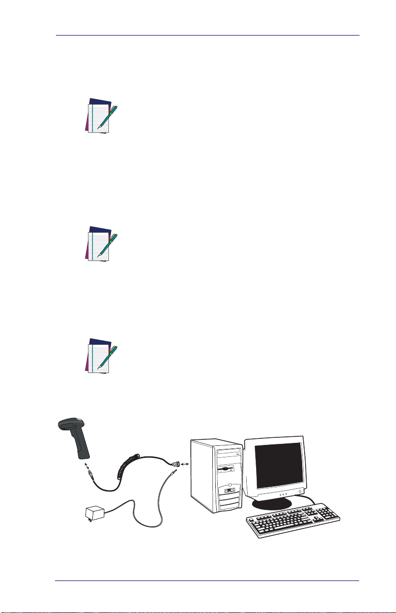
Connecting the Imager with an RS232 Serial Port
These instructions are for use with the RS-232
cable. This includes both Power Off the Terminal (P.O.T.) and external power.
NOTE
1. Turn off power to the terminal/computer.
2. Connect the appropriate interface cable to the imager.
For the imager to work properly, you must have
the correct cable for your type of terminal/computer.
NOTE
2
4
Product Reference Guide 1-3
3
Page 10
Getting Started
3. Plug the serial connector into the serial port on your computer.
Tighten the two screws to secure the connector to the port.
4. If the terminal does not support Power Off the Terminal (P.O.T.)
connections plug the power supply into the host connector and the
AC outlet.
5. Once the imager has been fully connected, power up the computer.
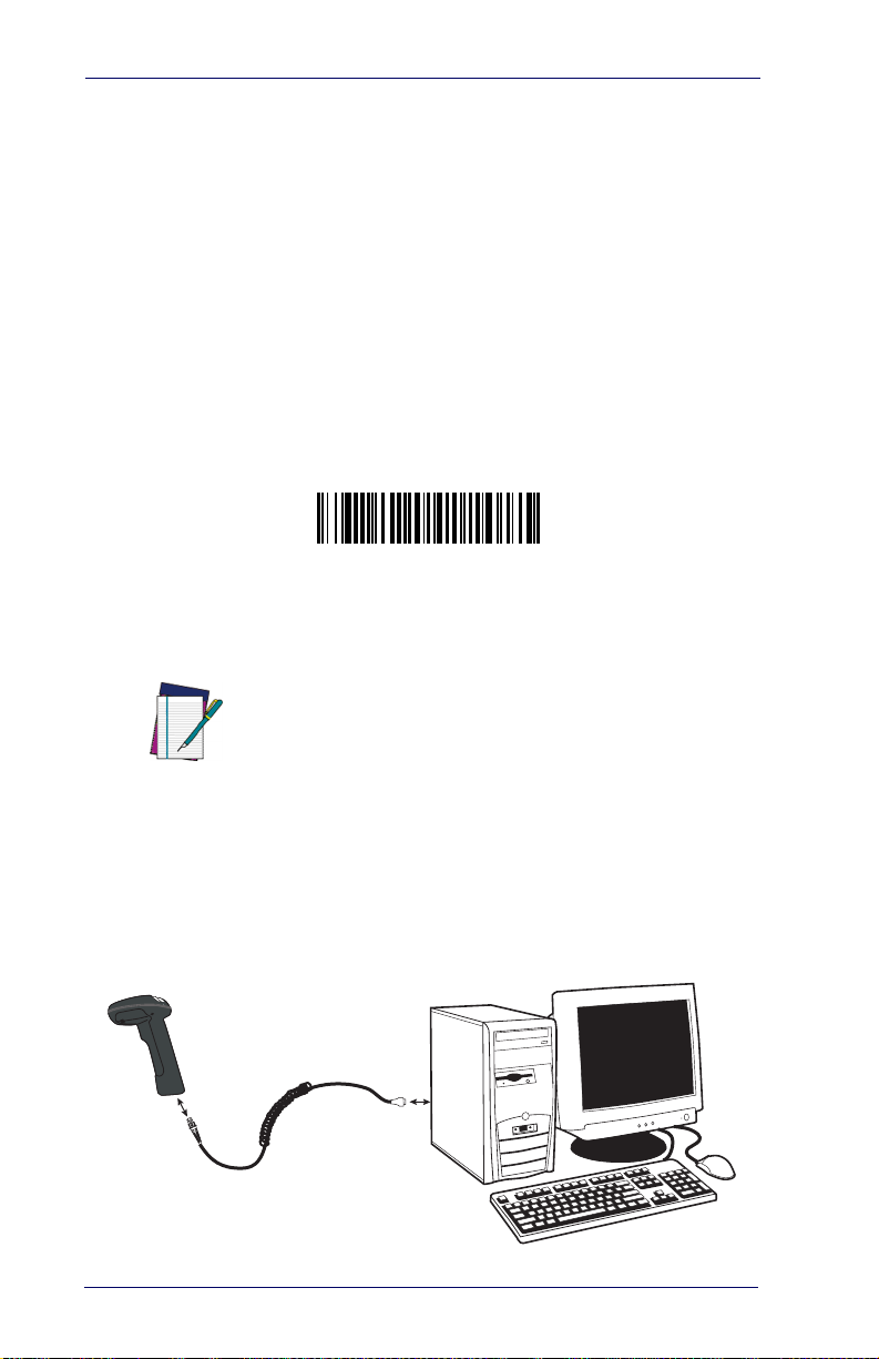
All communication parameters between the imager and terminal must
match for correct data transfer through the serial port using RS-232 protocol. Scanning the RS-232 interface bar code, programs the imager for
an RS-232 interface at 38,400 baud, parity–none, 8 data bits, 1 stop bit,
and adds a suffix of a CR LF.
RS-232 Interface
Connecting the Imager with USB
This interface applies to USB compatible models only.
NOTE
An Imager can be connected to the USB port of a computer.
1. Connect the appropriate interface cable to the Imager and to the
computer.
1-4 DuraLine™ 2D Imagers
Page 11
Connecting the Imager with USB
2. The Imager beeps.
3. Verify Imager operation by scanning the part number bar code
from the back cover of this manual.
The following USB “Plug and Play” codes are
supported on specific models. Refer to the
Product Reference Guide to determine if this
NOTE
interface applies to your unit.
For additional USB programming and technical information, visit the
WASP website listed on the back cover of this manual.
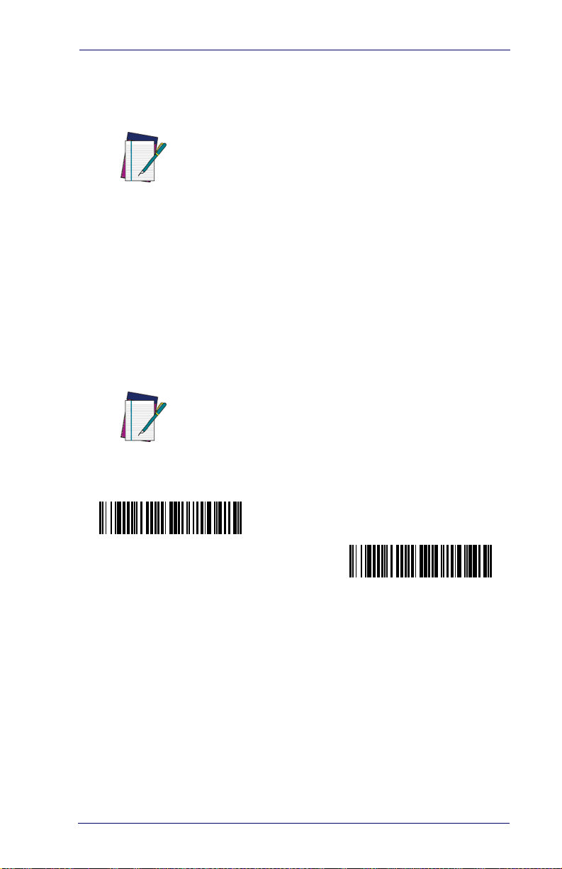
IBM SurePos
Scan one of the following “Plug and Play” codes to program the Imager
for IBM SurePos (USB Hand Held Imager) or IBM SurePos (USB
Tabletop Imager).
After scanning one of these codes, you must
power cycle the cash register
NOTE
IBM SurePos
(USB Hand Held Imager) Interface
IBM SurePos
(USB Tabletop Imager) Inter-
face
Product Reference Guide 1-5
Page 12

Getting Started
Each bar code above also programs the following suffixes for each symbology:
Symbology Suffix
EAN-8 0C
EAN-13 16
UPC-A 0D
UPC-E 0A
Code 39 00 0A 0B
Interleaved 2 of 5 00 0D 0B
Code 128 00 18 0B
The following USB “Plug and Play” codes (USB
Keyboard - PC, USB Keyboard - Mac, and USB
HID) are supported on specific Imager models.
Check your model type to determine if this inter-
NOTE
face applies to your unit.
USB PC or Macintosh® Keyboard
Scan one of the following codes to program the Imager for USB PC Keyboard or USB Macintosh Keyboard. Scanning these codes adds a CR
and selects the terminal ID (USB PC Keyboard - 124, USB Macintosh
Keyboard - 125).
USB Keyboard (PC)
USB Keyboard (Mac)
USB HID
Scan the following code to program the Imager for USB HID bar code
Imagers. Scanning this code changes the terminal ID to 131.
USB HID Bar Code Imager
1-6 DuraLine™ 2D Imagers
Page 13

Chapter 2
Terminal Interfaces
Terminal ID
If your interface is not a standard PC AT, refer to Supported Terminals on
page 2-2
minal ID bar code below, then scan the numeric bar code(s) on the Pro-
gramming Chart on page B-5
your terminal ID. Scan
For example, an IBM AT terminal has a Terminal ID of 003. You would
scan the
page B-5
the digits (before scanning Save), scan the
on page B-4
code again.
, and locate the Terminal ID number for your PC. Scan the Ter -
of this manual to program the Imager for
Save to save your selection.
Terminal ID bar code, then 0, 0, 3 from the Programming Chart on
of this manual, then Save. If you make an error while scanning
Discard code marked Discard
, scan the Terminal ID bar code, scan the digits, and the Save
Terminal ID
Save
After scanning one of these codes, you must
power cycle your computer.
NOTE
Product Reference Guide 2-1
Page 14

Terminal Interfaces
Supported Terminals
Terminal Model(s) Terminal ID
IBM SurePOS USB Hand Held Imager
IBM SurePOS USB Tabletop Imager
RS-232 True
RS-232 TTL 000
Serial Wedge 050
USB COM Port Emulation
USB PC Keyboard
USB Mac Keyboard
USB HID POS
a. Applies to USB models only. It is best to use the Plug and Play bar
codes located in the Quick Reference Guide, to program these interfaces, rather than scanning the terminal ID listed in this table.
b. Default for RS-232 models
128
129
000
130
124
125
131
a
a
b
a
a
a
a
2-2 DuraLine™ 2D Imagers
Page 15
Keyboard Country
Keyboard Country
Scan the appropriate country code below to program the keyboard for
your country. As a general rule, the following characters are supported,
but need special care for countries other than the United States:
@ | $ # { } [ ] = / ‘ \ < > ~
* United States
Belgium
Brazil
Canada (French)
Czechoslovakia
Denmark
Finland (Sweden)
France
Germany/Austria
Greece
Hungary
Israel (Hebrew)
Product Reference Guide 2-3
Page 16
Terminal Interfaces
Keyboard Country (continued)
Italy
Latin America
Netherlands (Dutch)
Norway
Poland
Portugal
Romania
Russia
SCS
Slovakia
Spain
Sweden
Switzerland (German)
2-4 DuraLine™ 2D Imagers
Page 17
Keyboard Style
Keyboard Country (continued)
Tur key F
Tur k ey Q
U.K.
Keyboard Style
This programs keyboard styles, such as Caps Lock and Shift Lock.
Default = Regular.
Regular is used when you normally have the Caps Lock key off.
* Regular
Caps Lock is used when you normally have the Caps Lock key on.
Caps Lock
Shift Lock is used when you normally have the Shift Lock key on (not
common to U.S. keyboards).
Shift Lock
Product Reference Guide 2-5
Page 18
Terminal Interfaces
Automatic Caps Lock is used if you change the Caps Lock key on and off.
The software tracks and reflects if you have Caps Lock on or off (AT and
PS/2 only). This selection can only be used with systems that have an
LED which notes the Caps Lock status.
Automatic Caps Lock
Autocaps via NumLock bar code should be scanned in countries (e.g.,
Germany, France) where the Caps Lock key cannot be used to toggle
Caps Lock. The NumLock option works similarly to the regular Auotcaps, but uses the NumLock key to retrieve the current state of the Caps
Lock.
Autocaps via NumLock
Emulate External Keyboard should be scanned if you do not have an
external keyboard (IBM AT or equivalent).
Emulate External Keyboard
After scanning the Emulate External Keyboard
bar code, you must power cycle your computer.
NOTE
2-6 DuraLine™ 2D Imagers
Page 19
Keyboard Modifiers
Keyboard Modifiers
This modifies special keyboard features, such as CTRL+ ASCII codes
and Turbo Mode.
Control + ASCII Mode On
The Imager sends key combinations for ASCII control characters for values 00-1F. Refer to
CTRL+ ASCII Values. Default = Off
Control + ASCII Mode On
Turbo Mode— The imager sends characters to a terminal faster. If
the terminal drops characters, do not use Turbo Mode. Default = Off
Keyboard Function Relationships on page 9-1 for
* Control + ASCII Mode Off
Turbo Mode On
* Turbo Mode Off
Numeric Keypad Mode— Sends numeric characters as if entered
from a numeric keypad. Default = Off
Numeric Keypad Mode On
* Numeric Keypad Mode Off
Product Reference Guide 2-7
Page 20
Terminal Interfaces
RS-232 Modifiers
RS-232 Baud Rate
Baud Rate sends the data from the imager to the terminal at the specified
rate. The host terminal must be set for the same baud rate as the imager.
Default = 38,400.
300
600
1200
2400
4800
9600
19200
* 38400
57,600
115,200
2-8 DuraLine™ 2D Imagers
Page 21
RS-232 Modifiers
RS-232 Word Length: Data Bits, Stop Bits, and Parity
Data Bits sets the word length at 7 or 8 bits of data per character. If an
application requires only ASCII Hex characters 0 through 7F decimal
(text, digits, and punctuation), select 7 data bits. For applications which
require use of the full ASCII set, select 8 data bits per character. Default
= 8.
Stop Bits sets the stop bits at 1 or 2. Default = 1.
Parity provides a means of checking character bit patterns for validity.
Default = None.
7 Data, 1 Stop, Parity Even
7 Data, 1 Stop, Parity None
7 Data, 1 Stop, Parity Odd
7 Data, 2 Stop, Parity Even
7 Data, 2 Stop Parity None
7 Data, 2 Stop, Parity Odd
8 Data, 1 Stop, Parity Even
* 8 Data, 1 Stop, Parity None
8 Data, 1 Stop, Parity Odd
Product Reference Guide 2-9
Page 22

Terminal Interfaces
RS-232 Receiver Time-Out
The unit stays awake to receive data until the RS-232 Receiver TimeOut expires. A manual or serial trigger resets the time-out. When an
RS-232 receiver is sleeping, a character may be sent to wake up the
receiver and reset the time-out. A transaction on the CTS line will also
wake up the receiver. The receiver takes 300 milliseconds to completely
come up. Change the RS-232 receiver time-out by scanning the bar
code below, then scanning digits from the
5
of this manual, then scanning Save. The range is 0 to 300 seconds.
Default = 0 seconds (no time-out - always on).
RS-232 Receiver Time-Out
Programming Chart on page B-
2-10 DuraLine™ 2D Imagers
Page 23
RS-232 Modifiers
RS-232 Handshaking
RS-232 handshaking is a set of rules concerning the exchange of data
between serially communicating devices.
If using RTS/CTS handshaking, the imager issues an active RTS signal
to the receiving device. The imager waits to send its data until it detects
an active CTS signal from the receiving device. The imager then sends
its data while checking the CTS signal before the transmission of each
data character. If an inactive CTS signal is detected at any time, the
imager halts transmission until it detects another active CTS signal.
When the imager has finished transmitting data, it issues an inactive
RTS signal to the receiving device. Default = RTS/CTS Off, XON/XOFF
Off, and ACK/NAK Off.
RTS/CTS On
* RTS/CTS Off
XON/XOFF On
* XON/OFF Off
ACK/NAK On
* ACK/NAK Off
Product Reference Guide 2-11
Page 24

Terminal Interfaces
NOTES
2-12 DuraLine™ 2D Imagers
Page 25

Chapter 3
Output
Good Read Indicators
Beeper – Good Read
The beeper may be programmed On or Off in response to a good read.
Turning this option off, only turns off the beeper response to a good read
indication. All error and menu beeps are still audible. Default = On.
* On
Off
Beeper Volume – Good Read
The beeper volume codes modify the volume of the beep the imager
emits on a good read. Default = High.
Low
Medium
*High
Off
Product Reference Guide 3-1
Page 26
Output
Beeper Pitch – Good Read
The beeper pitch codes modify the pitch (frequency) of the beep the
imager emits on a good read. Default = Medium.
Low (1250 Hz)
Medium (2300 Hz)
* High (2900 Hz)
Beeper Duration – Good Read
The beeper duration codes modify the length of the beep the imager
emits on a good read. Default = Normal.
* Normal Beep
Short Beep
LED – Good Read
The LED indicator can be programmed On or Off in response to a good
read. Default = On.
* On
Off
3-2 DuraLine™ 2D Imagers
Page 27

Good Read Delay
Number of Beeps – Good Read
The number of beeps of a good read can be programmed from 1 - 9.
The same number of beeps will be applied to the beeper and LED in
response to a good read. For example, if you program this option to have
five beeps, there will be five beeps and five LED flashes in response to a
good read. The beeps and LED flashes are in sync with one another. To
change the number of beeps, scan the bar code below and then scan a
digit (1-9) bar code and the Save
page B-5
of this manual. Default = One.
bar code on the Programming Chart on
Number of Pulses
Good Read Delay
This sets the minimum amount of time before the imager can read
another bar code. Default = No Delay.
* No Delay
Short Delay (500 ms)
Medium Delay (1,000 ms)
Long Delay (1,500 ms)
Product Reference Guide 3-3
Page 28

Output
User-Specified Good Read Delay
If you want to set your own length for the good read delay, scan the bar
code below, then set the delay (from 0-30,000 milliseconds) by scanning
digits from the
Programming Chart on page B-5, then scanning Save.
User-Specified Good Read Delay
Trigger Modes
Manual/Serial Trigger
You can activate the imager either by pressing the trigger, or using a serial
trigger command (see
ual trigger mode, the imager scans until a bar code is read, or until the
trigger is released.
When in serial mode, the imager scans until a bar code has been read or
until the deactivate command is sent. In serial mode, the imager can also
be set to turn itself off after a specified time has elapsed (see
Out
, which follows).
Trigger Commands on page 11-5). When in man-
Read Time-
* Manual/Serial Trigger
Read Time-Out
Use this selection to set a time-out (in milliseconds) of the imager’s trigger when using serial commands to trigger the imager, or if the imager is
in manual trigger mode. Once the imager has timed out, you can activate the imager either by pressing the trigger or using a serial trigger
command. After scanning the Read Time-Out bar code, set the time-out
duration (from 0-300,000 milliseconds) by scanning digits from the
gramming Chart on page B-5
, then scanning Save. Default = 0 (infinite,
or no time-out).
Read Time-Out
3-4 DuraLine™ 2D Imagers
Pro-
Page 29

Trigger Modes
Manual Trigger, Low Power
The imager powers down until the trigger is pulled. When the trigger is
pulled, the imager powers up and operates until there is no triggering for
the time set with the Low Power Time-Out bar code below. There is a
delay of up to one second in operation when the imager is first triggered,
but there is no delay when operating in low power time-out mode.
Manual Trigger, Low Power
Low Power Time-Out Timer
Scan the Low Power Time-Out bar code to change the time-out duration (in seconds). Then scan the time-out duration (from 0-300 seconds) from the
120 seconds.
If the unit remains idle during the low power time-out interval, the unit
goes into low power mode. Whenever the trigger is enabled, the low
power time-out timer is reset.
Programming Chart on page B-5, and Save. Default =
Low Power Time-Out
This time-out does not begin until the imager
time-out setting has expired.
NOTE
Product Reference Guide 3-5
Page 30

Output
Scan Stand Mode
When a unit is in Scan Stand mode, it remains idle as long as it sees the
Scan Stand symbol. (See
ferent code is presented, the Imager is triggered to read the new code.
Note:The imager automatically adjusts the illumination LEDs to the
lowest light level possible to maintain a good lock on the Scan Stand
symbol. When a symbol is presented, the imager’s light levels adjust to
the saved setting (see
Scan Stand Symbol
When a unit is in Scan Stand mode, the LEDs shine at the Scan Stand
symbol on the base of the stand which tells it to remain idle. When the
Scan Stand symbol is covered, the imager turns the LEDs on at the configured power level (Default High) and attempts to find and decode bar
codes in its field of view.
Scan Stand Symbol that follows.) When a dif-
LED Power Level on page 3-9).
Scan Stand Mode
Scan Stand Symbol
Presentation Mode
This programs the imager to work in Presentation Mode.
Presentation Mode
3-6 DuraLine™ 2D Imagers
Page 31

Hands Free Time-Out
Presentation LED Timer
When an imager is in presentation mode, the LEDs turn off immediately
after a bar code is decoded. The imager can be programmed to continue
scanning and to keep the LEDs on for a short time after by scanning the
LEDs On bar code below. Default = LEDs On.
* LEDs On
LEDs Off
Presentation Sensitivity
Presentation Sensitivity is a numeric range that increases or decreases the
imager's reaction time to bar code presentation. To set the sensitivity,
scan the Sensitivity bar code, then scan the degree of sensitivity (from 0-
20) from the
sensitive setting, and 20 is the least sensitive. Default = 1.
Programming Chart on page B-5, and Save. 0 is the most
Sensitivity
Hands Free Time-Out
The Scan Stand and Presentation Modes are referred to as “hands free”
modes. If the imager’s trigger is pulled when using a hands free mode,
the imager changes to manual trigger mode. You can set the time the
imager should remain in manual trigger mode by setting the Hands Free
Time-Out. Once the time-out value is reached, (if there have been no
further trigger pulls) the imager reverts to the original hands free mode.
Product Reference Guide 3-7
Page 32

Output
Scan the Hands Free Time-Out bar code, then scan the time-out duration
(from 0-300,000 milliseconds) from the
Programming Chart on page B-5,
and Save. Default = 5,000 ms.
Hands Free Time-Out
Double Read Timeout
This sets the time period before the imager can read the same bar code a
second time. Setting a reread delay protects against accidental rereads of
the same bar code. Longer delays are effective in minimizing accidental
rereads at POS (point of sale). Use shorter delays in applications where
repetitive bar code scanning is required. Default = Medium.
Reread Delay only works when in Presentation Mode (see
Mode on page 3-6
Short (500 ms)
Long (1000 ms)
).
* Medium (750 ms)
Extra Long (2000 ms)
Presentation
User-Specified Double Read Timeout
If you want to set your own length for the reread delay, scan the bar code
below, then set the delay (from 0-30,000 milliseconds) by scanning digits from the
Programming Chart on page B-5, then scanning Save.
User-Specified Double Read Timeout
3-8 DuraLine™ 2D Imagers
Page 33

LED Power Level
LED Power Level
This selection allows you to adjust LED and aimer brightness. Off is
used when no illumination is needed. Low is used if low illumination is
sufficient. High (the default) is the brightest setting.
If you have an aimer delay programmed (see
Aimer Delay on page 3-11),
the aimer will be at 100% power during the delay, regardless of the LED
Power Level.
If you scan the Off bar code, both the aimer and
illumination lights turn off, making it impossible
to scan bar codes in low light. To turn the LED
Power Level back on, move to a brightly lit area
NOTE
* High (100%)
and scan either the Low or the High bar code
below.
Off
Low (50%)
Product Reference Guide 3-9
Page 34

Output
Illumination Lights
If you want the illumination lights on while reading a bar code, scan the
Lights On bar code, below. However, if you want to turn just the lights
off, scan the Lights Off bar code.
This setting does not affect the aimer light. The
aiming light can be set using Aimer Mode (see
Aimer Mode on page 3-12).
NOTE
* Lights On
Lights Off
Imager Time-Out
Imager Time-Out powers down the imager after the unit has been idle
for the specified time. To prevent the imager from powering down, set
this time-out to 0. Scan the bar code below, then set the time-out by
scanning digits (from 0 - 999,999 ms) from the
page B-5
3-10 DuraLine™ 2D Imagers
, then scanning Save. Default = 120,000 ms.
Imager Time-Out
Programming Chart on
Page 35

Aimer Delay
Aimer Delay
The aimer delay allows a delay time for the operator to aim the imager
before the picture is taken. Use these codes to set the time between when
the trigger is pulled and when the picture is taken. During the delay
time, the aiming light will appear, but the LEDs won’t turn on until the
delay time is over.
200 milliseconds
400 milliseconds
(no delay)
* Off
User-Specified Aimer Delay
If you want to set your own length for the duration of the delay, scan the
bar code below, then set the time-out by scanning digits (0 - 4,000 ms)
from the
Programming Chart on page B-5 of this manual, then scan Save.
Delay Duration
Product Reference Guide 3-11
Page 36

Output
Aimer Mode
This feature allows you to lower peak current during scanning by alternating the aimer and illumination LEDs. When the Interlaced bar code
is scanned, the aimer and illumination LEDs are not allowed to be on at
the same time. While this does limit peak current during scanning, the
scanner performance may be slower. When the Concurrent bar code is
scanned, the aimer and illumination LEDs are allowed to light at the
same time. Select Off if you don’t want to use either aimer mode.
Off
* Concurrent
Interlaced
Centering
Use Centering to narrow the imager’s field of view to make sure the
imager reads only those bar codes intended by the user. For instance, if
multiple codes are placed closely together, centering will insure that only
the desired codes are read. (Centering can be used in conjunction with
Aimer Delay on page 3-11, for the most error-free operation in applica-
tions where multiple codes are spaced closely together. Using the Aimer
Delay and Centering features, the imager can emulate the operation of
older systems, such as linear laser bar code imagers.)
Figure 3-1. Centering Example
Bar Code 1
Bar Code 2
3-12 DuraLine™ 2D Imagers
Page 37

Centering
In the example in Figure 3-1, the gray area is the full imager field of view
and the white area is the centering window. Bar Code 1 will not be read,
while Bar Code 2 will be.The default centering window is a 128x96 pixel
area in the center of the imager’s field of view. The following diagram
illustrates the default top, bottom, left, and right pixel positions, measured from the top and the left side of the imager’s field of view, which is
640 by 480 pixels.
100%
40%
60%
100%
0
Bottom
Left
Right
40% 60%
Top
Default
Center
If a bar code is not within the predefined window, it will not be decoded
or output by the imager. If centering is turned on by scanning Centering
On, the imager only reads codes that intersect the centering window you
specify using the To p , Bottom, Left, or Right bar codes.
Product Reference Guide 3-13
Page 38

Output
Scan Centering On, then scan one of the following bar codes to change
the top, bottom, left, or right of the centering window. Then scan the
percent you want to shift the centering window using digits on the
gramming Chart on page B-5
. Scan Save. Default Centering = 40% for
Pro-
Top and Left, 60% for Bottom and Right.
Centering On
* Centering Off
Top of Centering Window
Bottom of Centering Window
Left of Centering Window
Right of Centering Window
Decode Search Mode
There are three selectable decode (scanning) modes:
Full Omnidirectional - Searches for bar code features beginning at the
center of an image, and searches to the image’s limits. This mode reads
all symbologies (including OCR), in any orientation. The Full Omnidirectional search is very thorough which may slow performance time.
This search mode is the default setting.
NOTE
Full Omnidirectional
3-14 DuraLine™ 2D Imagers
Page 39

Output Sequence Overview
Quick Omnidirectional - This is an abbreviated search for bar code features around the center region of an image. This mode quickly reads all
symbologies in any orientation. The Quick Omnidirectional mode may
miss some off-center symbols, as well as larger Data Matrix and QR
Code symbols.
Quick Omnidirectional
Advanced Linear Decoding - Performs quick horizontal linear scans in a
center band of the image. This mode is not omnidirectional, but does
quickly read linear and stacked bar codes. Advanced Linear Decoding
cannot read 2D, OCR, or Postal symbols.
This search mode is the default setting for point-and-shoot PDF imagers.
Advanced Linear Decoding
Output Sequence Overview
Require Output Sequence
When turned off, the bar code data will be output to the host as the
Imager decodes it. When turned on, all output data must conform to an
edited sequence or the Imager will not transmit the output data to the
host device.
This selection is unavailable when the Multiple
Symbols Selection is turned on.
NOTE
Product Reference Guide 3-15
Page 40

Output
Output Sequence Editor
This programming selection allows you to program the Imager to output
data (when scanning more than one symbol) in whatever order your
application requires, regardless of the order in which the bar codes are
scanned. Reading the Default Sequence symbol programs the Imager to
the Universal values, shown below. These are the defaults. Be certain
you want to delete or clear all formats before you read the Default
Sequence symbol.
To make Output Sequence Editor selections,
you’ll need to know the code I.D., code length,
and character match(es) your application
requires. Use the Alphanumeric symbols from
the
NOTE
To Add an Output Sequence
1. Scan the Enter Sequence symbol (see Multiple Symbols on page 3-
20
).
2. Code I.D.
On the Symbology Chart on page A-1, find the symbology to which
you want to apply the output sequence format. Locate the Hex
value for that symbology and scan the 2 digit hex value from the
Programming Chart on page B-5.
Programming Chart on page B-5 to read
these options.
3. Length
Specify what length (up to 9999 characters) of data output will be
acceptable for this symbology. Scan the four digit data length from
the Programming Chart. (Note: 50 characters is entered as 0050.
9999 is a universal number, indicating all lengths.) When calculating the length, you must count any programmed prefixes, suffixes,
or formatted characters as part of the length (unless using 9999).
4. Character Match Sequences
On the "ASCII Conversion Chart (Code Page 1252)" on page A-
4, find the Hex value that represents the character(s) you want to
match. Use the Programming Chart to read the alphanumeric
combination that represents the ASCII characters. (99 is the Universal number, indicating all characters.)
3-16 DuraLine™ 2D Imagers
Page 41

Output Sequence Overview
5. End Output Sequence Editor
Scan F F to enter an Output Sequence for an additional symbology, or Save to save your entries.
Other Programming Selections
Discard
This exits without saving any Output Sequence changes.
Output Sequence Examples
In this example, you are scanning Code 93, Code 128, and Code 39 bar
codes, but you want the imager to output Code 39 1st, Code 128 2nd,
and Code 93 3rd, as shown below.
Code 93 must be enabled to use this example.
NOTE
A - Code 39
B - Code 128
C - Code 93
You would set up the sequence editor with the following command line:
SEQBLK62999941FF6A999942FF69999943FF
Product Reference Guide 3-17
Page 42

Output
The breakdown of the command line is shown below:
SEQBLK sequence editor start command
62 code identifier for Code 39
9999 code length that must match for Code 39, 9999 = all lengths
41 start character match for Code 39, 41h = “A”
FF termination string for first code
6A code identifier for Code 128
9999 code length that must match for Code 128, 9999 = all lengths
42 start character match for Code 128, 42h = “B”
FF termination string for second code
69 code identifier for Code 93
9999 code length that must match for Code 93, 9999 = all lengths
43 start character match for Code 93, 43h = “C”
FF termination string for third code
To program the previous example using specific lengths, you would have
to count any programmed prefixes, suffixes, or formatted characters as
part of the length. If you use the example on page 3-17, but assume a
<CR> suffix and specific code lengths, you would use the following command line:
SEQBLK62001141FF6A001242FF69001143FF
The breakdown of the command line is shown below:
SEQBLK sequence editor start command
62 code identifier for Code 39
0011 Code 39 code length (9) plus CR suffix (2) = 11
41 start character match for Code 39, 41h = “A”
FF termination string for first code
6A code identifier for Code 128
0012 Code 128 code length (10) plus CR suffix (2) = 12
42 start character match for Code 128, 42h = “B”
FF termination string for second code
69 code identifier for Code 93
0011 Code 93 code length (9) plus CR suffix (2) = 11
43 start character match for Code 93, 43h = “C”
FF termination string for third code
3-18 DuraLine™ 2D Imagers
Page 43

Output Sequence Overview
Output Sequence Editor
Enter Sequence
Default Sequence
Require Output Sequence
When an output sequence is Required, all output data must conform to
an edited sequence or the imager will not transmit the output data to the
host device. When it’s On/Not Required, the imager will attempt to get
the output data to conform to an edited sequence, but if it cannot, the
imager transmits all output data to the host device as is.
When the output sequence is Off, the bar code data is output to the host
as the imager decodes it.
This selection is unavailable when the Multiple
Symbols Selection is turned on.
NOTE
Required
On/Not Required
*Off
Product Reference Guide 3-19
Page 44

Output
Multiple Symbols
This feature does not work when the Imager is
in Low Power mode.
NOTE
When this programming selection is turned On, it allows you to read
multiple symbols with a single pull of the Imager’s trigger. If you press
and hold the trigger, aiming the Imager at a series of symbols, it reads
unique symbols once, beeping (if turned on) for each read. The imager
attempts to find and decode new symbols as long as the trigger is pulled.
When this programming selection is turned Off, the Imager will only
read the symbol closest to the aiming beam.
On
* Off
No Read
With No Read turned On, the Imager notifies you if a code cannot be
read. If using a PowerView Scan Data Window, an “NR” appears when
a code cannot be read. If No Read is turned Off, the “NR” will not
appear.
On
* Off
If you want a different notation than “NR,” for example, “Error,” or
“Bad Code,” you can edit the output message using the
on page 5-5
3-20 DuraLine™ 2D Imagers
. The hex code for the No Read symbol is 9C.
Data Formatter
Page 45

Print Weight
Print Weight
Print Weight is used to adjust the way the imager reads Matrix symbols.
If a imager will be seeing consistently heavily printed matrix symbols,
then a print weight of 6 may improve the reading performance. For consistently light printing, a print weight of 2 may help. After scanning the
Set Print Weight bar code, set the print weight (from 1-7) by scanning
digits from the
Programming Chart on page B-5, then scanning Save.
Default = 4.
Set Print Weight
* Default
Video Reverse
Video Reverse is used to allow the imager to read bar codes that are
inverted. The “Off” bar code below is an example of this type of bar
code. If additional menuing is required, Video Reverse must be disabled
to read the menu bar codes and then re-enabled after menuing is completed.
Images downloaded from the unit will not be
reversed. This is a setting for decoding only.
NOTE
On
* Off
Product Reference Guide 3-21
Page 46

Output
Working Orientation
Some bar codes are direction-sensitive. For example, KIX codes and
OCR can misread when scanned sideways or upside down. Use the
working orientation settings if your direction-sensitive codes will not
usually be presented upright to the scanner. Default = Upright.
Upright:
Rotate Clockwise 90°:
Upside Down:
* Upright
Upside Down
Counterclockwise 90°:
Rotate
Rotate Clockwise 90°
Rotate Counterclockwise 90°
3-22 DuraLine™ 2D Imagers
Page 47

Chapter 4
Data Editing
Prefix/Suffix Overview
When a bar code is scanned, additional information is sent to the host
computer along with the bar code data. This group of bar code data and
additional, user-defined data is called a “message string.” The selections
in this section are used to build the user-defined data into the message
string.
Prefix and Suffix characters are data characters that can be sent before
and after scanned data. You can specify if they should be sent with all
symbologies, or only with specific symbologies. The following illustration shows the breakdown of a message string:
Prefix Scanned Data Suffix
1-11
alpha numeric
characters
variable length
1-11
alpha numeric
characters
Points to Keep In Mind
• It is not necessary to build a message string. The selections in this
chapter are only used if you wish to alter the default settings.
Default prefix = None. Default suffix = None.
• A prefix or suffix may be added or cleared from one symbology or
all symbologies.
Product Reference Guide 4-1
Page 48

Data Editing
• You can add any prefix or suffix from the ASCII Conversion Chart
(Code Page 1252) on page A-4
, plus Code I.D. and AIM I.D.
• You can string together several entries for several symbologies at
one time.
• Enter prefixes and suffixes in the order in which you want them to
appear on the output.
To Add a Prefix or Suffix:
Step 1. Scan the Add Prefix or Add Suffix symbol (page 4-4).
Step 2. Determine the 2 digit Hex value from the Symbology Chart (included
in "Symbology Chart" on page A-1) for the symbology to which you
want to apply the prefix or suffix. For example, for Code 128, Code ID
is “j” and Hex ID is “6A”.
Step 3. Scan the 2 hex digits from the Programming Chart on page B-5 of this
manual or scan 9, 9 for all symbologies.
Step 4. Determine the hex value from the ASCII Conversion Chart (Code
Page 1252) on page A-4, for the prefix or suffix you wish to enter.
Step 5. Scan the 2 digit hex value from the Programming Chart on page B-5
of this manual.
Step 6. Repeat Steps 4 and 5 for every prefix or suffix character.
Step 7. To add the Code I.D., scan 5, C, 8, 0.
To add AIM I.D., scan
To add a backslash (\), scan 5, C, 5, C.
To add a backslash (\) as in Step 7, you must
scan 5C twice – once to create the leading backslash and then to create the backslash itself.
NOTE
Step 8. Scan Save to exit and save, or scan Discard to exit without saving.
Repeat Steps 1-6 to add a prefix or suffix for another symbology.
5, C, 8, 1.
Example: Add a Suffix to a specific symbology
To send a CR (carriage return)Suffix for UPC only:
4-2 DuraLine™ 2D Imagers
Page 49

Prefix/Suffix Overview
Step 1. Scan Add Suffix.
Step 2. Determine the 2 digit hex value from the Symbology Chart (included
in ASCII Conversion Chart (Code Page 1252) on page A-4) for UPC.
Step 3. Scan 6, 3 from the Programming Chart on page B-5 of this manual.
Step 4. Determine the hex value from the ASCII Conversion Chart (Code
Page 1252) on page A-4, for the CR (carriage return).
Step 5. Scan 0, D from the Programming Chart on page B-5 of this manual.
Step 6. Scan Save, or scan Discard to exit without saving.
To Clear One or All Prefixes or Suffixes:
You can clear a single prefix or suffix, or clear all prefixes/suffixes for a
symbology. When you Clear One Prefix (Suffix), the specific character
you select is deleted from the symbology you want. When you Clear All
Prefixes (Suffixes), all the prefixes or suffixes for a symbology are deleted.
Step 1. Scan the Clear One Prefix or Clear One Suffix symbol.
Step 2. Determine the 2 digit Hex value from the Symbology Chart (included
in ASCII Conversion Chart (Code Page 1252) on page A-4) for the
symbology from which you want to clear the prefix or suffix.
Step 3. Scan the 2 digit hex value from the Programming Chart on page B-5
of this manual or scan 9, 9 for all symbologies.
Your change is automatically saved.
To Add a Carriage Return Suffix to all Symbologies
Scan the following bar code if you wish to add a carriage return suffix to
all symbologies at once. This action first clears all current suffixes, then
programs a carriage return suffix for all symbologies.
Add CR Suffix
All Symbologies
Product Reference Guide 4-3
Page 50

Data Editing
Prefix Selections
Add Prefix
Clear All Prefixes
Suffix Selections
Add Suffix
Clear One Prefix
Clear One Suffix
Clear All Suffixes
Function Code Transmit
When this selection is enabled and function codes are contained within
the scanned data, the imager transmits the function code to the terminal.
Charts of these function codes are provided in
on page 9-3
4-4 DuraLine™ 2D Imagers
. Default = Enable.
* Enable
Supported Interface Keys
Disable
Page 51

Intercharacter, Interfunction, and Intermessage Delays
Intercharacter, Interfunction, and
Intermessage Delays
Some terminals drop information (characters) if data comes through too
quickly. Intercharacter, interfunction, and intermessage delays slow the
transmission of data, increasing data integrity.
Each delay is composed of a 5 millisecond step. You can program up to
99 steps (of 5 ms each) for a range of 0-495 ms.
Intercharacter Delay
An intercharacter delay of up to 495 milliseconds may be placed between
the transmission of each character of scanned data. Scan the Intercharacter Delay bar code below, then scan the number of milliseconds and the
SAVE bar code using the
Programming Chart on page B-5 of this manual.
Prefix Scanned Data Suffix
1 2345
Intercharacter Delay
Intercharacter Delay
To remove this delay, scan the Intercharacter Delay bar code, then set the
number of steps to 0. Scan the SAVE bar code using the
Chart on page B-5
NOTE
Product Reference Guide 4-5
of this manual.
Intercharacter delays are not supported in USB
serial emulation.
Programming
Page 52

Data Editing
User Specified Intercharacter Delay
An intercharacter delay of up to 495 milliseconds may be placed after the
transmission of a particular character of scanned data. Scan the Delay
Length bar code below, then scan the number of milliseconds and the
SAVE bar code using the
Next, scan the Character to Trigger Delay bar code, then the 2-digit hex
value for the ASCII character that will trigger the delay ASCII Conversion
Chart (Code Page 1252) on page A-4
Delay Length
To remove this delay, scan the Delay Length bar code, and set the number of steps to 0. Scan the SAVE bar code using the
on page B-5
of this manual.
Programming Chart on page B-5of this manual.
.
Character to Trigger Delay
Programming Chart
Interfunction Delay
An interfunction delay of up to 495 milliseconds may be placed between
the transmission of each segment of the message string. Scan the Interfunction Delay bar code below, then scan the number of milliseconds
and the SAVE bar code using the
manual.
Prefix Scanned Data Suffix
1 2345STX HT CR LF
To remove this delay, scan the Interfunction Delay bar code, then set the
number of steps to 0. Scan the SAVE bar code using the
Chart on page B-5
4-6 DuraLine™ 2D Imagers
of this manual.
Programming Chart on page B-5 of this
Interfunction Delays
Interfunction Delay
Programming
Page 53

Intercharacter, Interfunction, and Intermessage Delays
Intermessage Delay
An intermessage delay of up to 495 milliseconds may be placed between
each scan transmission. Scan the Intermessage Delay bar code below,
then scan the number of milliseconds and the SAVE bar code using the
Programming Chart on page B-5 of this manual.
2nd Scan Transmission1st Scan Transmission
Intermessage Delay
Intermessage Delay
To remove this delay, scan the Intermessage Delay bar code, then set the
number of steps to 0. Scan the SAVE bar code using the
Chart on page B-5
of this manual.
Programming
Product Reference Guide 4-7
Page 54

Data Editing
NOTES
4-8 DuraLine™ 2D Imagers
Page 55

Chapter 5
Data Formatting
Data Format Editor Introduction
You may use the Data Format Editor to change the imager’s output. For
example, you can use the Data Format Editor to insert characters at certain points in bar code data as it is scanned. The selections in the following pages are used only if you wish to alter the output. Default Data
Format setting = None.
Normally, when you scan a bar code, it gets outputted automatically;
however when you do a format, you must use a “send” command (see
Send Commands on page 5-3) within the format program to output data.
Multiple formats may be programmed into the imager. They are stacked
in the order in which they are entered. However, the following list presents the order in which formats are applied:
1. Specific Term ID, Actual Code ID, Actual Length
2. Specific Term ID, Actual Code ID, Universal Length
3. Specific Term ID, Universal Code ID, Actual Length
4. Specific Term ID, Universal Code ID, Universal Length
5. Universal Term ID, Actual Code ID, Actual Length
6. Universal Term ID, Actual Code ID, Universal Length
7. Universal Term ID, Universal Code ID, Actual Length
8. Universal Term ID, Universal Code ID, Universal Length
If you have changed data format settings, and wish to clear all formats
and return to the factory defaults, scan the Default Data Format code on
* Default Data Format on page 5-5.
Product Reference Guide 5-1
Page 56

Data Formatting
To Add a Data Format
Step 1. Scan the Enter Data Format symbol (page 5-5).
Step 2. Primary/Alternate Format
Determine if this will be your primary data format, or one of 3 alternate
formats. (Alternate formats allow you “single shot” capability to scan
one bar code using a different data format. After the one bar code
has been read, the imager reverts to the primary data format. See
page 5-6.) If you are programming the primary format, scan 0 using
the Programming Chart on page B-5 of this manual. If you are pro-
gramming an alternate format, scan 1, 2, or 3, depending on the alternate format you are programming.
Step 3. Terminal Type
Refer to Supported Terminals on page 2-2 and locate the Terminal ID
number for your PC. Scan three numeric bar codes on the Program-
ming Chart on page B-5 to program the imager for your terminal ID
(you must enter 3 digits). For example, scan 124 for a USB keyboard.
The wildcard for all terminal types is 099.
NOTE
Step 4. Code I.D.
In Symbologies, find the symbology to which you want to apply the
data format. Locate the Hex value for that symbology and scan the 2
digit hex value from the Programming Chart on page B-5 of this man-
ual.
Step 5. Length
Specify what length (up to 9999 characters) of data will be acceptable
for this symbology. Scan the four digit data length from the Program-
ming Chart on page B-5 of this manual. (Note: 50 characters is
entered as 0050. 9999 is a universal number, indicating all lengths.)
Step 6. Editor Commands
Refer to Data Format Editor Introduction on page 5-1. Scan the sym-
5-2 DuraLine™ 2D Imagers
Page 57

Data Format Editor Introduction
bols that represent the command you want to enter. 94 alphanumeric
characters may be entered for each symbology data format.
Step 7. Scan Save from the Programming Chart on page B-5 of this manual
to save your entries.
Other Programming Selections
Clear One Data Format —
bology. If you are clearing the primary format, scan 0 from the
ming Chart on page B-5
of this manual. If you are clearing an alternate
This deletes one data format for one sym-
Program-
format, scan 1, 2, or 3, depending on the alternate format you are clearing. Scan the Terminal Type and Code I.D. (see
page 2-2
), and the bar code data length for the specific data format that
Supported Terminals on
you want to delete. All other formats remain unaffected.
Save—
from the Programming Chart on page B-5 of this manual. This
exits, saving any Data Format changes.
Discard—
from the Programming Chart on page B-5 of this manual. This
exits without saving any Data Format changes.
Data Format Editor Commands
Send Commands
F1 Send all characters followed by “xx” key or function code, starting from
current cursor position. Syntax = F1xx (xx stands for the hex value for
an ASCII code, see ASCII Conversion Chart (Code Page 1252) on
page A-4.)
F2 Send “nn” characters followed by “xx” key or function code, starting from
current cursor position. Syntax = F2nnxx (nn stands for the numeric
value (00-99) for the number of characters and xx stands for the hex
value for an ASCII code. See ASCII Conversion Chart (Code Page 1252)
on page A-4.)
F3 Send up to but not including “ss” character (Search and Send) starting
from current cursor position, leaving cursor pointing to “ss” character followed by “xx” key or function code. Syntax = F3ssxx (ss and xx both
stand for the hex values for ASCII codes, see ASCII Conversion Chart
(Code Page 1252) on page A-4.)
F4 Send “xx” character “nn” times (Insert) leaving cursor in current cursor
position. Syntax = F4xxnn (xx stands for the hex value for an ASCII
code, see ASCII Conversion Chart (Code Page 1252) on page A-4, and
nn is the numeric value (00-99) for the number of times it should be sent.)
E9 Send all but the last “nn” characters, starting from the current cursor posi-
tion. Syntax = E9nn (nn is the numeric value (00-99) for the number of
characters that will not be sent at the end of the message.)
Product Reference Guide 5-3
Page 58

Data Formatting
Move Commands
F5 Move the cursor ahead “nn” characters from current cursor position.
Syntax = F5nn (nn stands for the numeric value (00-99) for the number
of characters the cursor should be moved ahead.)
F6 Move the cursor back “nn” characters from current cursor position.
Syntax = F6nn (nn stands for the numeric value (00-99) for the number
of characters the cursor should be moved back.)
F7 Move the cursor to the beginning of the data string. Syntax = F7.
EA Move the cursor to the end of the data string. Syntax = EA
Search Commands
F8 Search ahead for “xx” character from current cursor position, leaving cur-
sor pointing to “xx” character. Syntax = F8xx (xx stands for the hex
value for an ASCII code, see ASCII Conversion Chart (Code Page 1252)
on page A-4.)
F9 Search back for “xx” character from current cursor position, leaving cursor
pointing to “xx” character. Syntax = F9xx (xx stands for the hex value
for an ASCII code, see ASCII Conversion Chart (Code Page 1252) on
page A-4.)
E6 Search ahead for the first non “xx” character from the current cursor posi-
tion, leaving cursor pointing to non “xx” character. Syntax = E6xx (xx
stands for the hex value for an ASCII code, see ASCII Conversion Chart
(Code Page 1252) on page A-4.
E7 Search back for the first non “xx” character from the current cursor posi-
tion, leaving cursor pointing to non “xx” character. Syntax = E7xx (xx
stands for the hex value for an ASCII code, see ASCII Conversion Chart
(Code Page 1252) on page A-4.)
Miscellaneous Commands
FB Suppress all occurrences of up to 15 different characters, starting at the
current cursor position, as the cursor is advanced by other commands.
When the FC command is encountered, the suppress function is termi-
nated. The cursor is not moved by the FB command. Syntax = FBn-
nxxyy . .zz where nn is a count of the number of suppressed characters
in the list and xxyy .. zz is the list of characters to be suppressed. (xx
stands for the hex value for an ASCII code, see ASCII Conversion Chart
(Code Page 1252) on page A-4.)
FC Disables suppress filter and clear all suppressed characters. Syntax =
FC.
E4 Replaces up to 15 characters in the data string with user specified char-
acters. Replacement continues until the E5 command is encountered.
Syntax = E4nnxx1xx2yy1yy2...zz1zz2 where nn is the total count of both
characters to be replaced plus replacement characters; xx
acters to be replaced and xx
through zz
E5 Terminates character replacement. Syntax = E5.
FE Compare character in current cursor position to the character “xx.” If
characters are equal, increment cursor. If characters are not equal, no
format match. Syntax = FExx (xx stands for the hex value for an ASCII
code, see ASCII Conversion Chart (Code Page 1252) on page A-4.)
EC Check to make sure there is an ASCII number at the current cursor posi-
tion. If character is not numeric, format is aborted. Syntax = EC.
5-4 DuraLine™ 2D Imagers
and zz2.
1
defines replacement characters, continuing
2
defines char-
1
Page 59

Data Format Editor Introduction
ED Check to make sure there is a non-numeric ASCII character at the current
cursor position. If character is numeric, format is aborted. Syntax = ED.
Data Format Editor
Enter Data Format
* Default Data Format
Clear One Data Format
Clear All Data Formats
Save
Discard
Data Formatter
When Data Formatter is turned off, the bar code data is output to the
host as read (including prefixes and suffixes). Choose one of the following options. Default = Data Formatter On, but Not Required.
* Data Formatter On,
but Not Required
Data Formatter Off
When Data Formatter is required, all input data must conform to an
edited format or the imager does not transmit the input data to the host
device.
Data Format On, Format Required
Product Reference Guide 5-5
Page 60

Data Formatting
Alternate Data Formats
Alternate formats allow you “single shot” capability to scan one bar code
using a different data format than your primary format. When data formats are programmed (see
programming the primary format, or an alternate format numbered 1, 2,
or 3.
An alternate format is initiated by scanning one of the 3 alternate format
bar codes below. The imager will scan the next bar code, formatting the
data with the selected alternate format, then revert immediately to the
primary format.
page 5-2), you must input whether you are
Alternate Data Format 1
Alternate Data Format 2
Alternate Data Format 3
5-6 DuraLine™ 2D Imagers
Page 61

Chapter 6
Symbologies
This programming section contains the following menu selections.
Refer to
Chapter 11 for settings and defaults.
·Linear Symbologies ·Japanese Post
·Australian Post ·Kix (Netherlands) Post
·Aztec Code Enable ·Korea Post
·British Post ·Matrix 2 of 5 Enable
·Canadian Post ·MaxiCode Enable
·China Post Enable ·MicroPDF417 Enable
·Codabar Enable ·MSI Enable
·Codablock F Enable ·PDF417 Enable
·Code 11 Enable ·Planet Code
·Code 128 Enable ·Plessey Code Enable
·Code 16K Enable ·PosiCode A and B Enable
·Code 2 of 5 Enable ·Postnet
·Code 39 Enable ·QR Code
·Code 49 Enable ·Micro QR Code
·Code 93 Enable ·RSS Expanded Enable
·Data Matrix Enable ·RSS Limited Enable
·EAN/JAN-13 Enable ·RSS-14 Enable
·EAN/JAN-8 Enable ·TCIF Linked Code 39 (TLC39)
·EAN•UCC Composite Codes ·Te le p en
·IATA Code 2 of 5 Enable ·UPC-A Enable
·Interleaved 2 of 5 Enable
·UPC-A/EAN-13 with
Extended Coupon Code
Product Reference Guide 6-1
Page 62

Symbologies
Linear Symbologies
All Symbologies
If you want to decode all the symbologies allowable for your imager, scan
the All Symbologies On code. If on the other hand, you want to decode
only a particular symbology, scan All Symbologies Off followed by the
On symbol for that particular symbology.
All Symbologies On
All Symbologies Off
Message Length Description
You are able to set the valid reading length of some of the bar code symbologies. If the data length of the scanned bar code doesn’t match the
valid reading length, the imager will issue an error beep. You may wish
to set the same value for minimum and maximum length to force the
imager to read fixed length bar code data. This helps reduce the chances
of a misread.
EXAMPLE: Decode only those bar codes with a count of 9-20 charac-
ters.
Min. length = 09Max. length = 20
EXAMPLE: Decode only those bar codes with a count of 15 charac-
ters.
Min. length = 15Max. length = 15
For a value other than the minimum and maximum message length
defaults, scan the bar codes included in the explanation of the symbology, then scan the digit value of the message length and
Programming Chart on page B-5 of this manual. The minimum
on the
and maximum lengths and the defaults are included with the respective
symbologies.
6-2 DuraLine™ 2D Imagers
Save bar codes
Page 63

Linear Symbologies
Codabar
Codabar Enable
* On
Codabar Start/Stop Characters
<Default All Codabar Settings>
Off
Start/Stop characters identify the leading and trailing ends of the bar
code. You may either transmit, or not transmit Start/Stop characters.
Default = Don’t Transmit.
Transmit
* Don’t Transmit
Codabar Check Character
Codabar check characters are created using different “modulos.” You can
program the imager to read only Codabar bar codes with Modulo 16
check characters. Default = No Check Character.
No Check Character indicates that the imager reads and transmits bar
code data with or without a check character.
When Check Character is set to Validate and Transmit, the imager will
only read Codabar bar codes printed with a check character, and will
transmit this character at the end of the scanned data.
Product Reference Guide 6-3
Page 64

Symbologies
When Check Character is set to Validate, but Don’t Transmit, the unit
will only read Codabar bar codes printed with a check character, but will
not transmit the check character with the scanned data.
* No Check Character
Validate Modulo 16, but
Don’t Transmit
Validate Modulo 16
and Transmit
Codabar Concatenation
Codabar supports symbol concatenation. When you enable concatenation, the imager looks for a Codabar symbol having a “D” start character,
adjacent to a symbol having a “D” stop character. In this case the two
messages are concatenated into one with the “D” characters omitted.
Default = On.
Character
Stop Start StopStart
Codabar
A12D D34A
Select Require to prevent the imager from decoding a single “D” Codabar symbol without its companion. This selection has no effect on Codabar symbols without Stop/Start D characters.
On
* Off
Require
6-4 DuraLine™ 2D Imagers
Page 65

Linear Symbologies
Codabar Message Length
Scan the bar codes below to change the message length. Refer to Mes-
sage Length Description on page 6-2
for additional information. Minimum and Maximum lengths = 2-60. Minimum Default = 4, Maximum
Default = 60.
Minimum Message Length
Maximum Message Length
Code 39
< Default All Code 39 Settings >
Code 39 Enable
* On
Off
Code 39 Start/Stop Characters
Start/Stop characters identify the leading and trailing ends of the bar
code. You may either transmit, or not transmit Start/Stop characters.
Default = Don’t Transmit.
Tr an s m it
* Don’t Transmit
Product Reference Guide 6-5
Page 66

Symbologies
Code 39 Check Character
No Check Character indicates that the imager reads and transmits bar code
data with or without a check character.
When Check Character is set to Validate, but Don’t Transmit, the unit only
reads Code 39 bar codes printed with a check character, but will not
transmit the check character with the scanned data.
When Check Character is set to
Validate and Transmit, the imager only
reads Code 39 bar codes printed with a check character, and will transmit this character at the end of the scanned data. Default = No Check
Character.
* No Check Character
Validate, but Don’t Transmit
Validate and Transmit
Code 39 Message Length
Scan the bar codes below to change the message length. Refer to Mes-
sage Length Description on page 6-2
for additional information. Minimum and Maximum lengths = 0-48. Minimum Default = 0, Maximum
Default = 48.
Minimum Message Length
Maximum Message Length
6-6 DuraLine™ 2D Imagers
Page 67

Linear Symbologies
Code 39 Append
This function allows the imager to append the data from several Code 39
bar codes together before transmitting them to the host computer.
When this function is enabled, the imager stores those Code 39 bar
codes that start with a space (excluding the start and stop symbols), and
does not immediately transmit the data. The imager stores the data in
the order in which the bar codes are read, deleting the first space from
each. The imager transmits the appended data when it reads a Code 39
bar code that starts with a character other than a space. Default = Off.
On
* Off
Code 32 Pharmaceutical (PARAF or Pharmacode)
Code 32 Pharmaceutical is a form of the Code 39 symbology used by
Italian pharmacies. This symbology is also known as PARAF.
Trioptic Code (
while scanning Code 32 Pharmaceutical codes.
NOTE
On
Product Reference Guide 6-7
page 6-33) must be turned off
* Off
Page 68

Symbologies
Full ASCII
If Full ASCII Code 39 decoding is enabled, certain character pairs
within the bar code symbol will be interpreted as a single character. For
example: $V will be decoded as the ASCII character SYN, and /C will
be decoded as the ASCII character #. Default = Off.
NUL %U DLE $P SP
SPACE
SOH $A DC1 $Q ! /A 1 1 A A Q Q a +A q +Q
STX$BDC2$R“/B 22BBRRb+Br+R
ETX $C DC3 $S # /C 3 3 C C S S c +C s +S
EOT $D DC4 $T $ /D 4 4 D D T T d +D t +T
ENQ $E NAK $U % /E 5 5 E E U U e +E u +U
ACK $F SYN $V & /F 6 6 F F V V f +F v +V
BEL $G ETB $W ‘ /G 7 7 G G W W g +G w +W
BS$H CAN$X ( /H 88 HHXXh+Hx +X
HT $I EM $Y ) /I 9 9 I I Y Y i +I y +Y
LF $J SUB $Z * /J : /Z J J Z Z j +J z +Z
VT $K ESC %A + /K ; %F K K [ %K k +K { %P
FF $L FS %B , /L < %G L L \ %L l +L | %Q
CR $M GS %C - - = %H M M ] %M m +M } %R
SO $N RS %D . . > %I N N ^ %N n +N ~ %S
SI $O US %E / /O ? %J O O _ %O o +O DEL %T
00@%VPP‘ %Wp+P
Character pairs /M and /N decode as a minus sign and period respectively.
Character pairs /P through /Y decode as 0 through 9.
Full ASCII On
* Full ASCII Off
6-8 DuraLine™ 2D Imagers
Page 69

Linear Symbologies
Code 39 Code Page
Code pages define the mapping of character codes to characters. If the
data received does not display with the proper characters, it may be
because the bar code being scanned was created using a code page that is
different from the one the host program is expecting. If this is the case,
scan the bar code below, select the code page with which the bar codes
were created (see
and scan the value and the
page B-5
of this manual. The data characters should then appear prop-
Code Page Mapping of Printed Bar Codes on page A-7)
Save bar code from the Programming Chart on
erly.
Code 39 Code Page
Interleaved 2 of 5
< Default All Interleaved 2 of 5 Settings >
Interleaved 2 of 5 Enable
* On
Off
Check Digit
No Check Digit indicates that the imager reads and transmits bar code data
with or without a check digit.
When Check Digit is set to
Validate, but Don’t Transmit, the unit only
reads Interleaved 2 of 5 bar codes printed with a check digit, but will not
transmit the check digit with the scanned data.
Product Reference Guide 6-9
Page 70

Symbologies
When Check Digit is set to Validate and Transmit, the imager only reads
Interleaved 2 of 5 bar codes printed with a check digit, and will transmit
this digit at the end of the scanned data. Default = No Check Digit.
* No Check Digit
Validate, but Don’t Transmit
Validate and Transmit
Interleaved 2 of 5 Message Length
Scan the bar codes below to change the message length. Refer to Mes-
sage Length Description on page 6-2
for additional information. Minimum and Maximum lengths = 2-80. Minimum Default = 4, Maximum
Default = 80.
Minimum Message Length
Maximum Message Length
6-10 DuraLine™ 2D Imagers
Page 71

Linear Symbologies
Code 93
< Default All Code 93 Settings >
Code 93 Enable
* On
Off
Code 93 Message Length
Scan the bar codes below to change the message length. Refer to Mes-
sage Length Description on page 6-2
mum and Maximum lengths = 0-80. Minimum Default = 0, Maximum
Default = 80.
for additional information. Mini-
Minimum Message Length
Maximum Message Length
Code 93 Code Page
Code pages define the mapping of character codes to characters. If the
data received does not display with the proper characters, it may be
because the bar code being scanned was created using a code page that is
different from the one the host program is expecting. If this is the case,
scan the bar code below, select the code page with which the bar codes
were created (see
and scan the value and the
page B-5
of this manual. The data characters should then appear prop-
Code Page Mapping of Printed Bar Codes on page A-7)
Save bar code from the Programming Chart on
erly.
Code 93 Code Page
Product Reference Guide 6-11
Page 72

Symbologies
Code 2 of 5
<Default All Code 2 of 5 Settings>
Code 2 of 5 Enable
On
* Off
Code 2 of 5 Message Length
Scan the bar codes below to change the message length. Refer to Mes-
sage Length Description on page 6-2
mum and Maximum lengths = 1-48. Minimum Default = 4, Maximum
Default = 48.
Minimum Message Length
for additional information. Mini-
Maximum Message Length
6-12 DuraLine™ 2D Imagers
Page 73

Linear Symbologies
IATA Code 2 of 5
<Default All Code IATA 2 of 5 Settings>
IATA Code 2 of 5 Enable
On
* Off
IATA Code 2 of 5 Message Length
Scan the bar codes below to change the message length. Refer to Mes-
sage Length Description on page 6-2
mum and Maximum lengths = 1-48. Minimum Default = 4, Maximum
Default = 48.
Minimum Message Length
for additional information. Mini-
Maximum Message Length
Product Reference Guide 6-13
Page 74

Symbologies
Matrix 2 of 5
<Default All Matrix 2 of 5 Settings>
Matrix 2 of 5 Enable
On
* Off
Matrix 2 of 5 Message Length
Scan the bar codes below to change the message length. Refer to Mes-
sage Length Description on page 6-2
mum and Maximum lengths = 1-80. Minimum Default = 4, Maximum
Default = 80.
Minimum Message Length
for additional information. Mini-
Maximum Message Length
Code 11
<Default All Code 11 Settings>
Code 11 Enable
On
* Off
6-14 DuraLine™ 2D Imagers
Page 75

Linear Symbologies
Check Digits Required
This option sets whether 1 or 2 check digits are required with Code 11
bar codes. Default = Two Check Digits.
One Check Digit
* Two Check Digits
Code 11 Message Length
Scan the bar codes below to change the message length. Refer to Mes-
sage Length Description on page 6-2
for additional information. Minimum and Maximum lengths = 1-80. Minimum Default = 4, Maximum
Default = 80.
Minimum Message Length
Maximum Message Length
Product Reference Guide 6-15
Page 76

Symbologies
Code 128
<Default All Code 128 Settings>
Code 128 Enable
* On
Off
ISBT 128 Concatenation
In 1994 the International Society of Blood Transfusion (ISBT) ratified a
standard for communicating critical blood information in a uniform
manner. The use of ISBT formats requires a paid license. The ISBT 128
Application Specification describes 1) the critical data elements for labeling blood products, 2) the current recommendation to use Code 128
due to its high degree of security and its space-efficient design, 3) a variation of Code 128 that supports concatenation of neighboring symbols,
and 4) the standard layout for bar codes on a blood product label. Use
the bar codes below to turn concatenation on or off. Default =Off.
On
* Off
6-16 DuraLine™ 2D Imagers
Page 77

Linear Symbologies
Code 128 Message Length
Scan the bar codes below to change the message length. Refer to Mes-
sage Length Description on page 6-2
for additional information. Minimum and Maximum lengths = 0-80. Minimum Default = 0, Maximum
Default = 80.
Minimum Message Length
Maximum Message Length
Code 128 Code Page
Code pages define the mapping of character codes to characters. If the
data received does not display with the proper characters, it may be
because the bar code being scanned was created using a code page that is
different from the one the host program is expecting. If this is the case,
scan the bar code below, select the code page with which the bar codes
were created (see
and scan the value and the
page B-5
of this manual. The data characters should then appear prop-
Code Page Mapping of Printed Bar Codes on page A-7)
Save bar code from the Programming Chart on
erly.
Code 128 Code Page
Telepen
<Default All Telepen Settings>
Product Reference Guide 6-17
Page 78

Symbologies
Telepen
On
* Off
Telepen Output
Using AIM Telepen Output, the imager reads symbols with start/stop
pattern 1 and decodes them as standard full ASCII (start/stop pattern 1).
When Original Telepen Output is selected, the imager reads symbols
with start/stop pattern 1 and decodes them as compressed numeric with
optional full ASCII (start/stop pattern 2). Default = AIM Telepen Out-
put.
* AIM Telepen Output
Original Telepen Output
Telepen Message Length
Scan the bar codes below to change the message length. Refer to Mes-
sage Length Description on page 6-2
for additional information. Minimum and Maximum lengths = 1-60. Minimum Default = 1, Maximum
Default = 60.
Minimum Message Length
Maximum Message Length
6-18 DuraLine™ 2D Imagers
Page 79

Linear Symbologies
UPC-A
<Default All UPC-A Settings>
UPC-A Enable
* On
Off
UPC-A Check Digit Transmit
This selection allows you to specify whether the check digit should be
transmitted at the end of the scanned data or not. Default = On.
* On
Off
UPC-A Number System
The numeric system digit of a U.P.C. symbol is normally transmitted at
the beginning of the scanned data, but the unit can be programmed so it
will not transmit it. Default = On.
* On
Off
Product Reference Guide 6-19
Page 80

Symbologies
UPC-A Addenda
This selection adds 2 or 5 digits to the end of all scanned UPC-A data.
Default = Off for both 2 Digit and 5 Digit Addenda.
2 Digit Addenda On
* 2 Digit Addenda Off
5 Digit Addenda On
* 5 Digit Addenda Off
UPC-A Addenda Required
When Required is scanned, the imager will only read UPC-A bar codes
that have addenda. You must then turn on a 2 or 5 digit addenda listed
on page 6-20. Default = Not Required.
Required
* Not Required
UPC-A Addenda Separator
When this feature is on, there is a space between the data from the bar
code and the data from the addenda. When turned off, there is no space.
Default = On.
* On
Off
6-20 DuraLine™ 2D Imagers
Page 81

Linear Symbologies
UPC-A/EAN-13 with Extended Coupon Code
Use the following codes to enable or disable UPC-A and EAN-13 with
Extended Coupon Code. Default = On.
* On
Off
UPC-E0
UPC-E0
<Default All UPC-E Settings>
Most U.P.C. bar codes lead with the 0 number system. For these codes,
use the UPC-E0 selection. If you need to read codes that lead with the 1
number system, use
* UPC-E0 On
UPC-E0 Expand
UPC-E1 on page 6-23. Default = On.
UPC-E0 Off
UPC-E Expand expands the UPC-E code to the 12 digit, UPC-A format. Default = Off.
On
* Off
Product Reference Guide 6-21
Page 82

Symbologies
UPC-E0 Addenda Required
When Addenda Required is set to on, the imager will only read UPC-E
bar codes that have addenda. Default = Not Required.
Required
* Not Required
UPC-E0 Addenda Separator
When this feature is on, there is a space between the data from the bar
code and the data from the addenda. When turned off, there is no space.
Default = On.
* On
Off
UPC-E0 Check Digit Transmit
Check Digit specifies whether the check digit should be transmitted at
the end of the scanned data or not. Default = On.
* On
Off
6-22 DuraLine™ 2D Imagers
Page 83

Linear Symbologies
UPC-E0 Number System
The numeric system digit of a U.P.C. symbol is normally transmitted at
the beginning of the scanned data, but the unit can be programmed so it
will not transmit it. Default = On.
* On
Off
UPC-E0 Addenda
This selection adds 2 or 5 digits to the end of all scanned UPC-E data.
Default = Off for both 2 Digit and 5 Digit Addenda.
2 Digit Addenda On
* 2 Digit Addenda Off
5 Digit Addenda On
* 5 Digit Addenda Off
UPC-E1
Most U.P.C. bar codes lead with the 0 number system. For these codes,
use UPC-E0 (page 6-21). If you need to read codes that lead with the 1
number system, use the UPC-E1 selection. Default = Off.
UPC-E1 On
* UPC-E1 Off
Product Reference Guide 6-23
Page 84

Symbologies
EAN/JAN-13
<Default All EAN/JAN Settings>
EAN/JAN-13 Enable
* On
Off
EAN/JAN-13 Check Digit Transmit
This selection allows you to specify whether the check digit should be
transmitted at the end of the scanned data or not. Default = On.
* On
Off
EAN/JAN-13 Addenda
This selection adds 2 or 5 digits to the end of all scanned EAN/JAN-13
data.
Default = Off for both 2 Digit and 5 Digit Addenda.
2 Digit Addenda On
* 2 Digit Addenda Off
5 Digit Addenda On
* 5 Digit Addenda Off
6-24 DuraLine™ 2D Imagers
Page 85

Linear Symbologies
EAN/JAN-13 Addenda Required
When Addenda Required is set to on, the imager will only read EAN/
JAN-13 bar codes that have addenda. Default = Not Required.
Required
* Not Required
EAN/JAN-13 Addenda Separator
When this feature is on, there is a space between the data from the bar
code and the data from the addenda. When turned off, there is no space.
Default = On.
* On
Off
If you want to enable or disable EAN13 with
Extended Coupon Code, refer to
13 with Extended Coupon Code on page 6-21
NOTE
ISBN Translate
UPC-A/EAN-
.
This selection causes EAN-13 Bookland symbols to be translated into
their equivalent ISBN number format. Default = Off.
On
* Off
Product Reference Guide 6-25
Page 86

Symbologies
EAN/JAN-8
<Default All EAN/JAN-8 Settings>
EAN/JAN-8 Enable
* On
Off
EAN/JAN-8 Check Digit Transmit
This selection allows you to specify whether the check digit should be
transmitted at the end of the scanned data or not. Default = On.
* On
Off
EAN/JAN-8 Addenda
This selection adds 2 or 5 digits to the end of all scanned EAN/JAN-8
data.
Default = Off for both 2 Digit and 5 Digit Addenda.
2 Digit Addenda On
* 2 Digit Addenda Off
5 Digit Addenda On
* 5 Digit Addenda Off
6-26 DuraLine™ 2D Imagers
Page 87

Linear Symbologies
EAN/JAN-8 Addenda Required
When Addenda Required is set to on, the imager will only read EAN/
JAN-8 bar codes that have addenda. Default = Not Required.
Required
* Not Required
EAN/JAN-8 Addenda Separator
When this feature is on, there is a space between the data from the bar
code and the data from the addenda. When turned off, there is no space.
Default = On.
* On
Off
Product Reference Guide 6-27
Page 88

Symbologies
MSI
<Default All MSI Settings>
MSI Enable
On
* Off
MSI Check Character
Different types of check characters are used with MSI bar codes. You
can program the imager to read MSI bar codes with Type 10 check characters. Default = Validate Type 10, but Don’t Transmit.
When Check Character is set to Validate and Transmit, the imager will
only read MSI bar codes printed with the specified type check character,
and will transmit this character at the end of the scanned data.
When Check Character is set to Validate, but Don’t Transmit, the unit
will only read MSI bar codes printed with the specified type check character, but will not transmit the check character with the scanned data.
* Validate Type 10, but Don’t
Tr an s m it
Validate Type 10 and Transmit
6-28 DuraLine™ 2D Imagers
Page 89

Linear Symbologies
MSI Message Length
Scan the bar codes below to change the message length. Refer to Mes-
sage Length Description on page 6-2
for additional information. Minimum and Maximum lengths = 4-48. Minimum Default = 4, Maximum
Default = 48.
Minimum Message Length
Maximum Message Length
Plessey Code
<Default All Plessey Code Settings>
Plessey Code Enable
On
* Off
Plessey Message Length
Scan the bar codes below to change the message length. Refer to Mes-
sage Length Description on page 6-2
for additional information. Minimum and Maximum lengths = 4-48. Minimum Default = 4, Maximum
Default = 48.
Minimum Message Length
Maximum Message Length
Product Reference Guide 6-29
Page 90

Symbologies
RSS-14
RSS-14 Enable
* On
RSS Limited
< Default All RSS Limited Settings >
RSS Limited Enable
< Default All RSS-14 Settings >
Off
* On
Off
6-30 DuraLine™ 2D Imagers
Page 91

Linear Symbologies
RSS Expanded
< Default All RSS Expanded Settings >
RSS Expanded Enable
* On
Off
RSS Expanded Message Length
Scan the bar codes below to change the message length. Refer to Mes-
sage Length Description on page 6-2
mum and Maximum lengths = 4-74. Minimum Default = 4, Maximum
Default = 74.
for additional information. Mini-
Minimum Message Length
Maximum Message Length
Product Reference Guide 6-31
Page 92

Symbologies
PosiCode
<Default All PosiCode Settings>
PosiCode A and B Enable
* On
Off
You have to have PosiCode A and B on to read any of the PosiCode symbologies.
A and B On
(No Limited)
A and B and Limited A On
(Limited B Off)
* A and B and Limited B On
(Limited A Off)
PosiCode Message Length
Scan the bar codes below to change the message length. Refer to Mes-
sage Length Description on page 6-2
for additional information. Minimum and Maximum lengths = 2-80. Minimum Default = 4, Maximum
Default = 48.
Minimum Message Length
Maximum Message Length
6-32 DuraLine™ 2D Imagers
Page 93

Stacked Symbologies
Trioptic Code
If you are going to scan Code 32 Pharmaceutical codes (
NOTE
page 6-7), Trioptic Code must be off.
Trioptic Code is used for labeling magnetic storage media.
On
* Off
Stacked Symbologies
Codablock F
<Default All Codablock F Settings>
Codablock F Enable
On
* Off
Codablock F Message Length
Scan the bar codes below to change the message length. Refer to Mes-
sage Length Description on page 6-2
for additional information. Minimum and Maximum lengths = 1-2048. Minimum Default = 1,
Maximum Default = 2048.
Minimum Message Length
Maximum Message Length
Product Reference Guide 6-33
Page 94

Symbologies
Code 16K
<Default All Code 16K Settings>
Code 16K Enable
On
* Off
Code 16K Message Length
Scan the bar codes below to change the message length. Refer to Mes-
sage Length Description on page 6-2
mum and Maximum lengths = 0-160. Minimum Default = 1,
Maximum Default = 160.
for additional information. Mini-
Minimum Message Length
Maximum Message Length
6-34 DuraLine™ 2D Imagers
Page 95

Stacked Symbologies
Code 49
<Default All Code 49 Settings>
Code 49 Enable
* On
Off
Code 49 Message Length
Scan the bar codes below to change the message length. Refer to Mes-
sage Length Description on page 6-2
mum and Maximum lengths = 1-81. Minimum Default = 1, Maximum
Default = 81.
for additional information. Mini-
Minimum Message Length
Maximum Message Length
Product Reference Guide 6-35
Page 96

Symbologies
PDF417
< Default All PDF417 Settings >
PDF417 Enable
* On
Off
PDF417 Message Length
Scan the bar codes below to change the message length. Refer to Mes-
sage Length Description on page 6-2
mum and Maximum lengths = 1-2750. Minimum Default = 1,
Maximum Default = 2750.
for additional information. Mini-
Minimum Message Length
Maximum Message Length
6-36 DuraLine™ 2D Imagers
Page 97

Stacked Symbologies
MicroPDF417
< Default All MicroPDF417 Settings >
MicroPDF417 Enable
On
* Off
MicroPDF417 Message Length
Scan the bar codes below to change the message length. Refer to Mes-
sage Length Description on page 6-2
mum and Maximum lengths = 1-366. Minimum Default = 1,
Maximum Default = 366.
for additional information. Mini-
Minimum Message Length
Maximum Message Length
EAN•UCC Composite Codes
Linear codes are combined with a unique 2D composite component to
form a new class called EAN•UCC Composite symbology. EAN•UCC
Composite symbologies allow for the co-existence of symbologies already
in use.
On
* Off
Product Reference Guide 6-37
Page 98

Symbologies
UPC/EAN Version
Scan the UPC/EAN Version On bar code to decode EAN•UCC Compos-
ite symbols that have a UPC or EAN linear component. (This does not
affect EAN•UCC Composite symbols with a UCC/EAN-128 or RSS
linear component.)
UPC/EAN Version On
* UPC/EAN Version Off
EAN•UCC Composite Code Message Length
Scan the bar codes below to change the message length. Refer to Mes-
sage Length Description on page 6-2
mum and Maximum lengths = 1-2435. Minimum Default = 1,
Maximum Default = 2435.
Minimum Message Length
for additional information. Mini-
Maximum Message Length
EAN•UCC Emulation
The imager can automatically format the output from any EAN•UCC
data carrier to emulate what would be encoded in an equivalent UCC/
EAN-128 or RSS and Composite symbol. EAN•UCC data carriers
include UPC-A and UPC-E, EAN-13 and EAN-8, ITF-14, UCC/EAN128, and EAN•UCC RSS and Composites. Data from 2D symbols
such as Aztec Code, Data Matrix, or QR Code, which encode a leading
FNC1, also invoke EAN•UCC emulation. If UCC/EAN-128 Emula-
6-38 DuraLine™ 2D Imagers
Page 99

Stacked Symbologies
tion is selected, the AIM Symbology Identifier is reported as “]C1”. If
RSS Emulation is selected, the AIM Symbology Identifier is reported as
“]e0.” Any application that accepts EAN•UCC data can be simplified
since it only needs to recognize one data carrier type. Default = No Emu-
lation.
RSS Emulation
128 Emulation
* EAN•UCC Emulation Off
TCIF Linked Code 39 (TLC39)
This code is a composite code since it has a Code 39 linear component
and a MicroPDF417 stacked code component. All bar code readers are
capable of reading the Code 39 linear component. The MicroPDF417
component can only be decoded if
ponent may be decoded as Code 39 even if TLC39 is off.
TLC39 On is selected. The linear com-
On
* Off
Product Reference Guide 6-39
Page 100

Symbologies
Postal Codes
For best performance when reading a postal
symbology, all other postal symbologies should
be turned off. The following postal codes can
NOTE
Postnet
Postnet Check Digit Transmit
This selection allows you to specify whether the check digit should be
transmitted at the end of the scanned data.
only be read by a full 2D Imager.
On
* Off
Transmit Check Digit
* Don’t Transmit Check Digit
6-40 DuraLine™ 2D Imagers
 Loading...