

Wasp 718W Installation Manual
1
N718W 7/99
TTAABBLLEE OOFF CCOONNTTEENNTTSS
718W
II
NNSSTTAALLLLAATTIIOONN
GG
UUIIDDEE
Directed Electronics, Inc.
®
What Is Included. . . . . . . . . . . . . . . . . . . . . . . . . . . . . . . . . . . . . . . . 2
Installation Points to Remember . . . . . . . . . . . . . . . . . . . . . . . . . . . 2
Determining Component Locations. . . . . . . . . . . . . . . . . . . . . . . . . 3
Control Module . . . . . . . . . . . . . . . . . . . . . . . . . . . . . . . . . . . . . . 3
Status LED . . . . . . . . . . . . . . . . . . . . . . . . . . . . . . . . . . . . . . . . . 3
Wire Connection Guide . . . . . . . . . . . . . . . . . . . . . . . . . . . . . . . . . . 4
Transmitter/Receiver Learn Routine . . . . . . . . . . . . . . . . . . . . . . . . 4
To Enter the Transmitter/Receiver Learn Routine . . . . . . . . . . . . . 4
Operation Settings Learn Routine . . . . . . . . . . . . . . . . . . . . . . . . . . 4
To Enter the Operation Settings Learn Routine. . . . . . . . . . . . . . . 5
Feature Descriptions . . . . . . . . . . . . . . . . . . . . . . . . . . . . . . . . . . . . 5
Shock Sensor Adjustment . . . . . . . . . . . . . . . . . . . . . . . . . . . . . . . . 5
To Adjust the Warn Away Level . . . . . . . . . . . . . . . . . . . . . . . . . . 6
To Test and Adjust the Current Warn Away Setting. . . . . . . . . . . . 6
To Adjust the Shock Sensor Full Trigger. . . . . . . . . . . . . . . . . . . . 7
To Test and Adjust the Current Full Trigger Setting . . . . . . . . . . . . 7
Troubleshooting. . . . . . . . . . . . . . . . . . . . . . . . . . . . . . . . . . . . . . . . 8
Do not disconnect the battery if the vehicle has an anti-theft-coded radio. If equipped with an air bag, avoid disconnecting the battery if possible.
IMPORTANT: Many airbag systems will display a diagnostic code through their warning lights after
they lose power. Disconnecting the battery requires this code to be erased, which can require a
trip to the dealer.
Before beginning the installation:
• Remove the domelight fuse.This prevents accidentally draining the battery.
• Roll down a window to avoid being locked out of the car.
INSTALLATION POINTS TO REMEMBER
2
© 1999 Directed Electronics, Inc. N718W 7/99
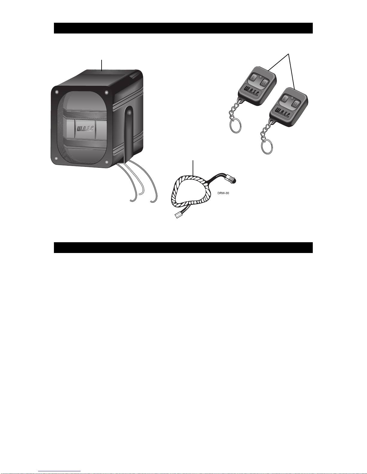
Two 491T Remote Transmitters
Control Module
Status LED
WHAT IS INCLUDED
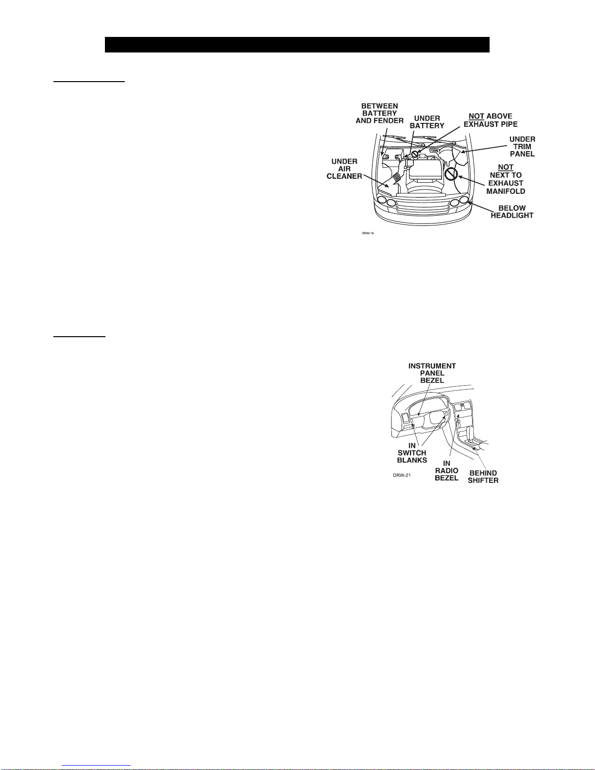
Control Module
Some things to remember about mounting the control module:
• Mount the control module in the engine compartment,
away from heat sources such as radiators, exhaust
manifolds, turbochargers, and heat shields. Also avoid
mounting the control module in areas that must be
accessed for routine vehicle maintenance .Some good
places for mounting the control module are shown in
the diagram at the right.
• Mount it where a thief cannot easily disconnect it,
whether the hood is open or shut. Both the control
module and its wires should be difficult to find. This
usually involves disguising the wire to look like a factory harness.
• Mount the unit with the siren facing down.This will prevent water damage to the unit.
• Route the wires away from the unit and make sure they are securely fastened away from the moving parts
of the engine.
• Place the antenna as high as possible and as straight as possible for maximum operating range.
Status LED
Things to remember when positioning the Status LED:
• It should be visible from both sides and the rear of the vehi-
cle, if possible.
• It needs at least 1/2" clearance to the rear.
• It is easiest to use a small removable panel, such as a switch
blank or a dash bezel.Remove it before drilling your 9/32" hole.
• Use quick-disconnects near the LED wires if the panel is re-
movable. This lets mechanics or other installers remove the
panel without cutting the wires.
DETERMINING COMPONENT LOCATIONS
3
© 1999 Directed Electronics, Inc. N718W 7/99
 Loading...