

Page 1
WASI POWERBALL // ASSEMBLY INSTRUCTIONS
Comprehensive research, development and testing under
actual conditions resulted in the German Lloyds approval
and certification of the WASI POWERBALL.
It is the first - and to date only - anchor-to-chain connector
that was awarded this prestigious certificate. In order to
insure proper function we recommend to proceed with the
assembly of the WASI POWERBALL according to following instructions:
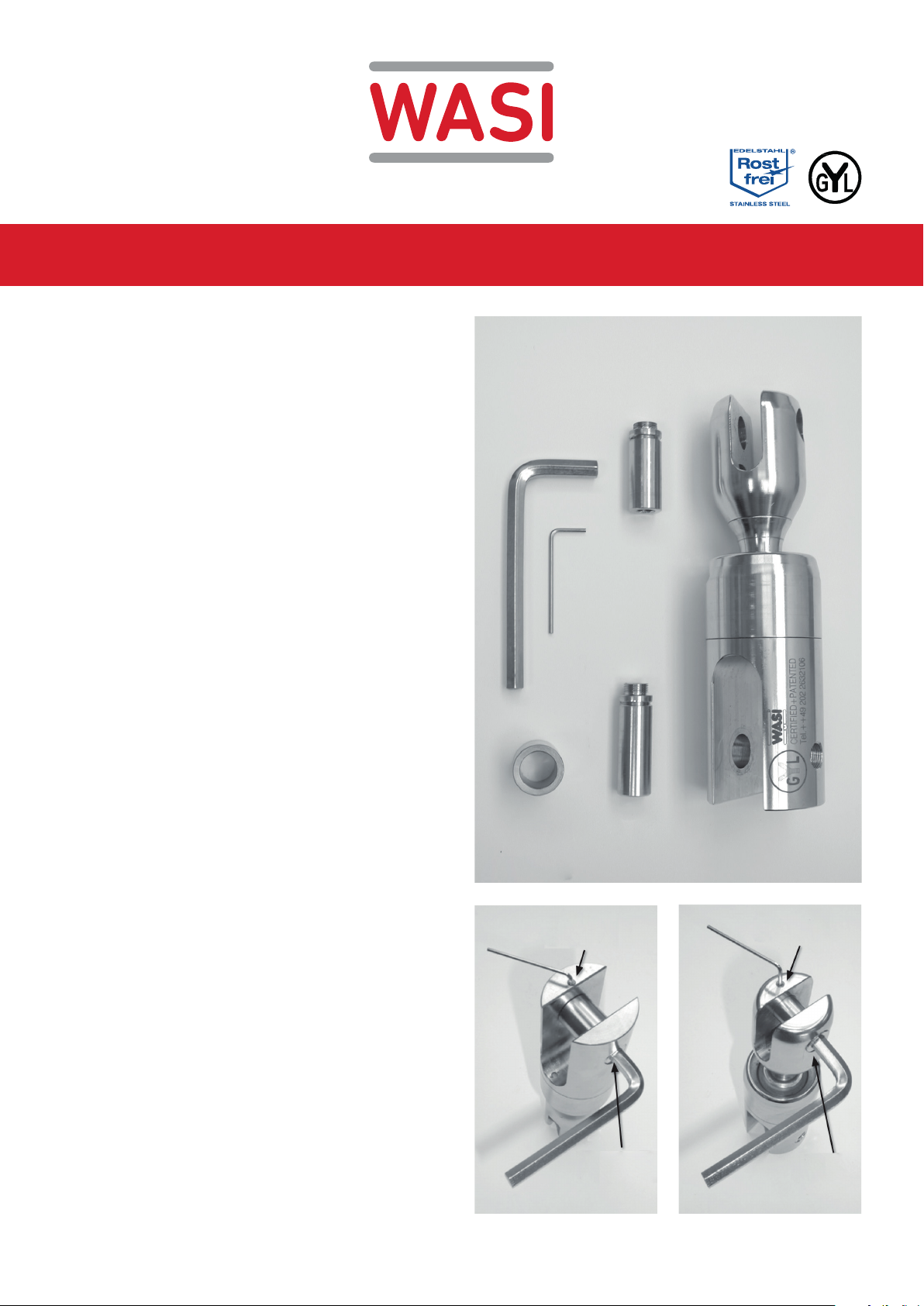
PICTURE 1
PARTS LIST
› A) Anchor-to-chain connector
› B) Allen keys (hexagon socket)
› C1) Bolt - anchor side
› C2) Bolt - chain side
› D) Anchor sleeve
PICTURE 2
CONNECTING TO ANCHOR
› Unscrew (approx. 3 full turns anti-clock wise) the set-
screw Pos.1 A with the small allen key (hex-socket)
› Unscrew (anti-clock wise) C1 bolt Pos.2 A with the big
allen key (hex socket) and remove anchor sleeve.
› Install anchor sleeve in head of anchor shaft
› Align WASI POWERBALL with hole in top end of the
anchor shaft.
› Fasten (clock-wise) the C1 bolt (Pos.2 A) firmly.
Do not overtighten bolt!
› Fasten (clock-wise) setscrew (Pos.1 A).
Do not overtighten setscrew!
› Fill the open end of the setscrew hole with
Marine-Silicone
PICTURE 1
B
POS. 1 A
A
C2
C1D
POS. 1 B
PICTURE 3
CONNECTING TO CHAIN
› Unscrew safety screw Pos.1 B and C2 bolt Pos.2 B
and connect the chain to the WASI POWERBALL in
the same way as with the anchor assembly. C2 Screw
in bolt and safety screw, but do not overtighten the
thread and fill the hole in the locking screw with marine
silicone.
IN CASE OF LOSS OF BOLTS, LOCKING SCREWS OR
ANCHOR SLEEVE SPARE PARTS CAN BE ORDERD AT YOUR
DISTRIBUTOR UNDER SPECIFICATION OF THE SERIAL NUMBER
OF YOUR WASI POWERBALL.
PICTURE 2
POS. 2 A
POS. 2 B
PICTURE 3
 Loading...