

Page 1
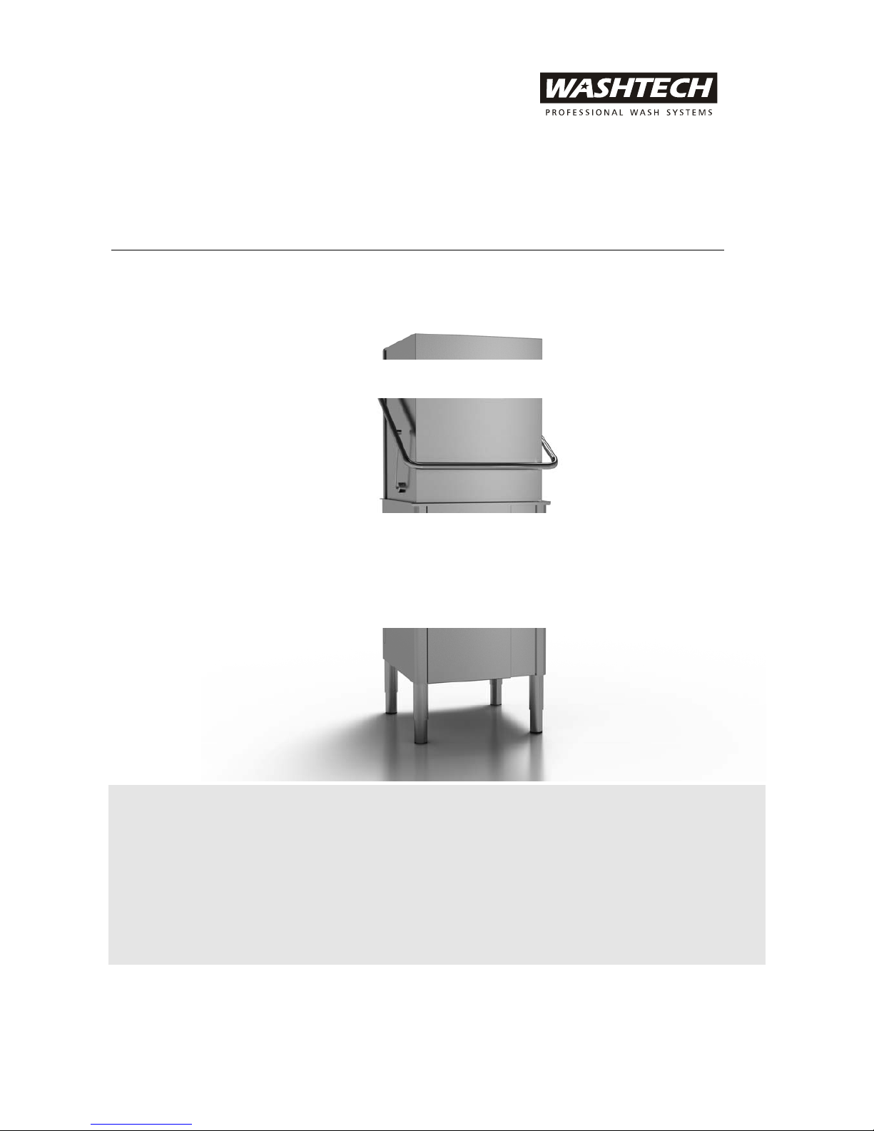
XP
PASSTHROUGH DISHWASHER
Service Manual
Page 2
WARNING
Before installation and commissioning, you must read the safety instructions and
warnings carefully and all the warning labels attached to the equipment.
IMPORTANT
Failure to comply (even partially) with the instructions given in this manual will
invalidate the product warranty and relieves the manufacturer of any responsibility.
IMPORTANT
The alteration of machine operation, design or the replacement of parts not
approved by the manufacturer may void warranties and approvals.
We have checked that the contents of this document correspond to the model described. There may be
discrepancies nevertheless, and no guarantee can be given that they are completely identical. The information
contained in this document is reviewed regularly and any necessary changes will be included in the next
edition. We welcome suggestions for improvement.
Document subject to change without prior notice.
Information supplied in this manual is copyright. No part of this work may be reproduced or copied in any
form or by any means, electronic or mechanical without the express permission of the author / publisher.
!
!
Service Manual XP-2
2
Revision 1C
Page 3

Contents
Safety Instructions ...........................................................................................................................................................................4
Installation ...........................................................................................................................................................................................5
Installation Diagram ............................................................................................................6
Bench Details........................................................................................................................7
Installation Checklist ........................................................................................................... 8
Maintenance Checklist ........................................................................................................9
Dishwashing Procedures .......................................................................................................................................................... 10
Troubleshooting Chart............................................................................................................................................................... 12
Operating Instructions............................................................................................................................................................... 14
Components .................................................................................................................................................................................... 15
Location and Access..........................................................................................................15
Timer....................................................................................................................................16
Rinse Thermostat...............................................................................................................17
Wash Thermostat...............................................................................................................18
Solenoid Valve....................................................................................................................19
Pressure Switch ..................................................................................................................20
Wash Pump.........................................................................................................................21
Detergent Pump.................................................................................................................22
Rinse Aid Injector..............................................................................................................23
Assembly & Electrical Diagrams.......................................................................................................................................... 24
Wiring Tray Assembly.......................................................................................................24
Control Panel Assembly ...................................................................................................25
Wash Assembly ..................................................................................................................26
Rinse Assembly ..................................................................................................................27
Rinse Tank Assembly ........................................................................................................ 28
Door Assembly ..................................................................................................................29
Door Link Assembly .........................................................................................................30
Rack Slide Assembly..........................................................................................................31
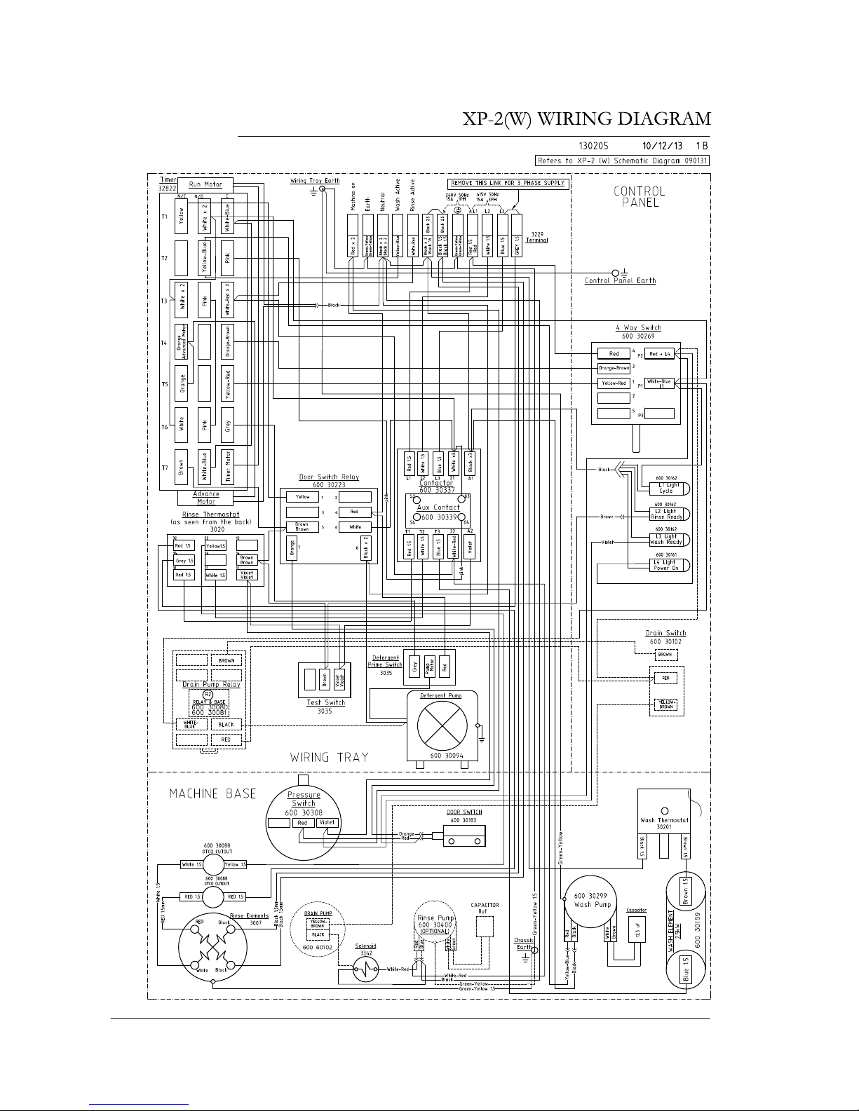
Schematic Diagrams .......................................................................................................... 32
Wiring Diagram..................................................................................................................33
Spare Parts ........................................................................................................................................................................................ 34
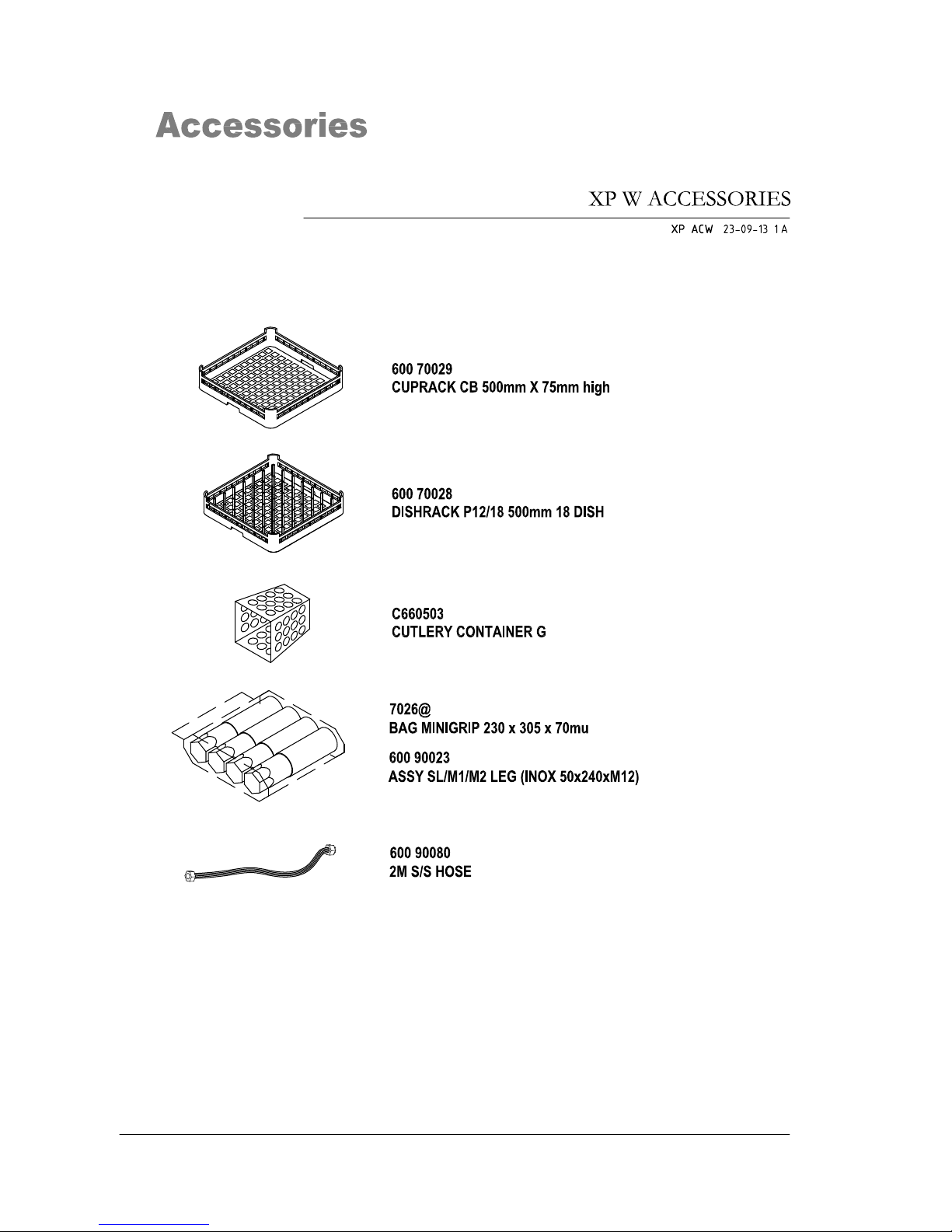
Accessories ....................................................................................................................................................................................... 36
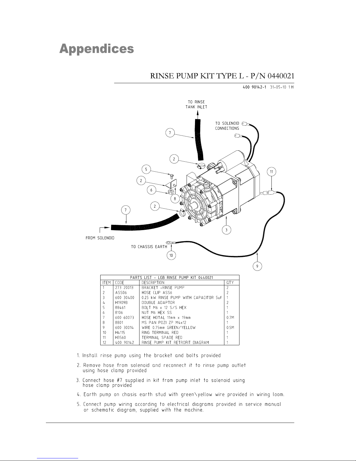
Appendices....................................................................................................................................................................................... 37
Rinse Pump Retrofit ................................................................................................................................37
Revisions............................................................................................................................................................................................ 38
Service Manual XP-2
3
Revision 1C
Page 4

Safety Instructions
WARNING
Equipment contains dangerous voltages and can be hazardous if installed or
operated incorrectly. Non-compliance with Warnings or failure to follow the
instructions contained in this manual can result in loss of life, severe personal
injury or serious damage to property.
Installation
Use qualified, skilled personnel
Follow installation instructions
Connect to correct voltage and supply current
Provide fully accessible Electrical Isolation Switch & water supply valves
Training and Supervision
Read and Understand the Operating instructions and train all staff
This appliance must not be operated by children or infirm persons
Machine panels must only be removed by suitably qualified and trained
personnel – internal hazards include live electrics and very hot surfaces
This appliance is not intended for use as a stepladder
Hot Surfaces
Some surfaces may be hot or very hot
Chemicals
Commercial dishwashing detergents are hazardous – handle with care
Read and follow the safety information found on the labels of detergent
containers and Material Safety Data Sheets
Use protective eyewear and clothing if decanting containers
Hot Water
Do not put hands in wash water which may be over 60°C and contain
hazardous caustic detergent
Rinse water can be over 90°C
Door safety switches are designed for emergency use only
Cleaning
Do not hose down the machine or splash water over the exterior
Watch for broken glass etc when cleaning the inside of the machine
Power Cord Replacement
If the supply cord is damaged, it must be replaced by the manufacturer
or its service agent or a similar qualified person in order to avoid a
hazard
Service Manual XP-2
4
Revision 1C
Page 5

Installation
WARNING
Installer must be suitably qualified and ensure compliance with all codes and
standards including AS/NZS3500.1.
Failure to comply even partially with installation instructions may void the
warranty.
Positioning
Unpack machine, check for damage and complete delivery. Install machine on sound
waterproof self-draining floor and use adjustable feet to level machine.
Allow room for detergent to one side of machine or in adjacent cupboard. 20litre container
requires about 450H x 250W x 350D, but smaller containers are available from many
suppliers.
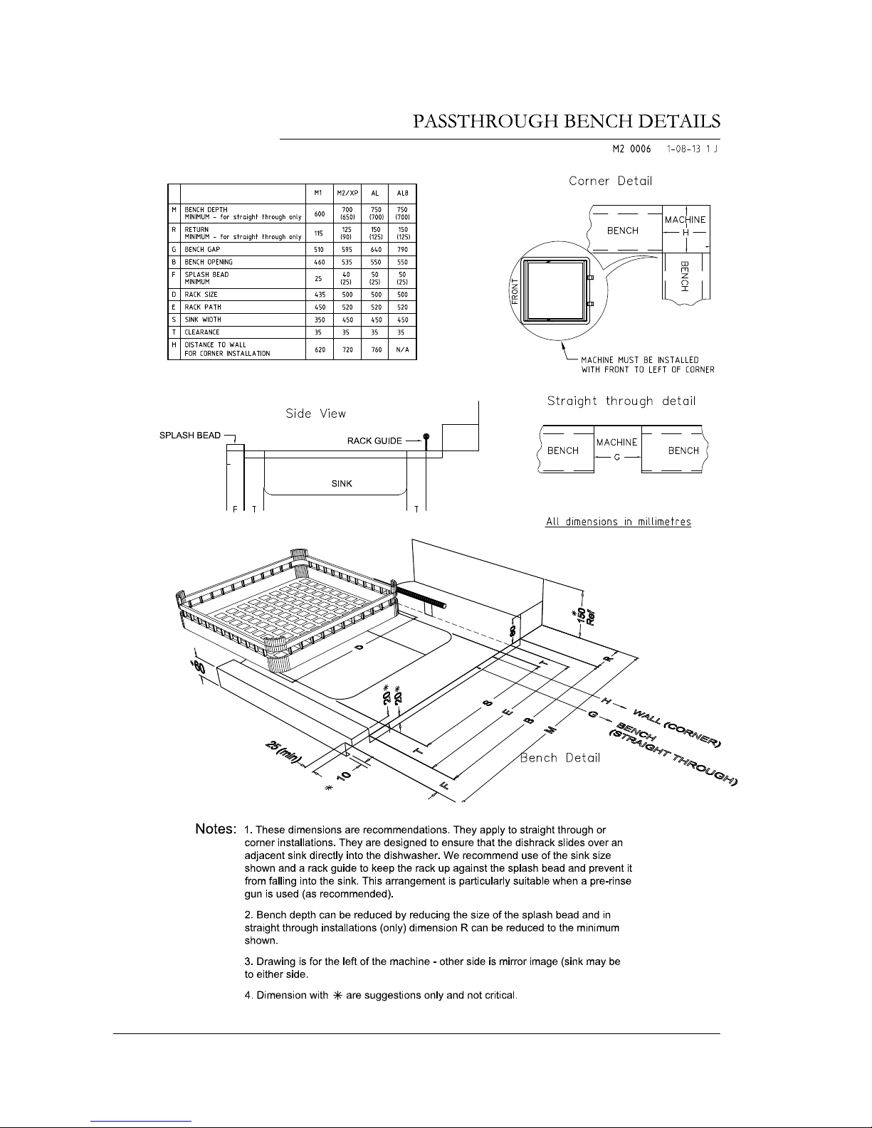
Benchwork
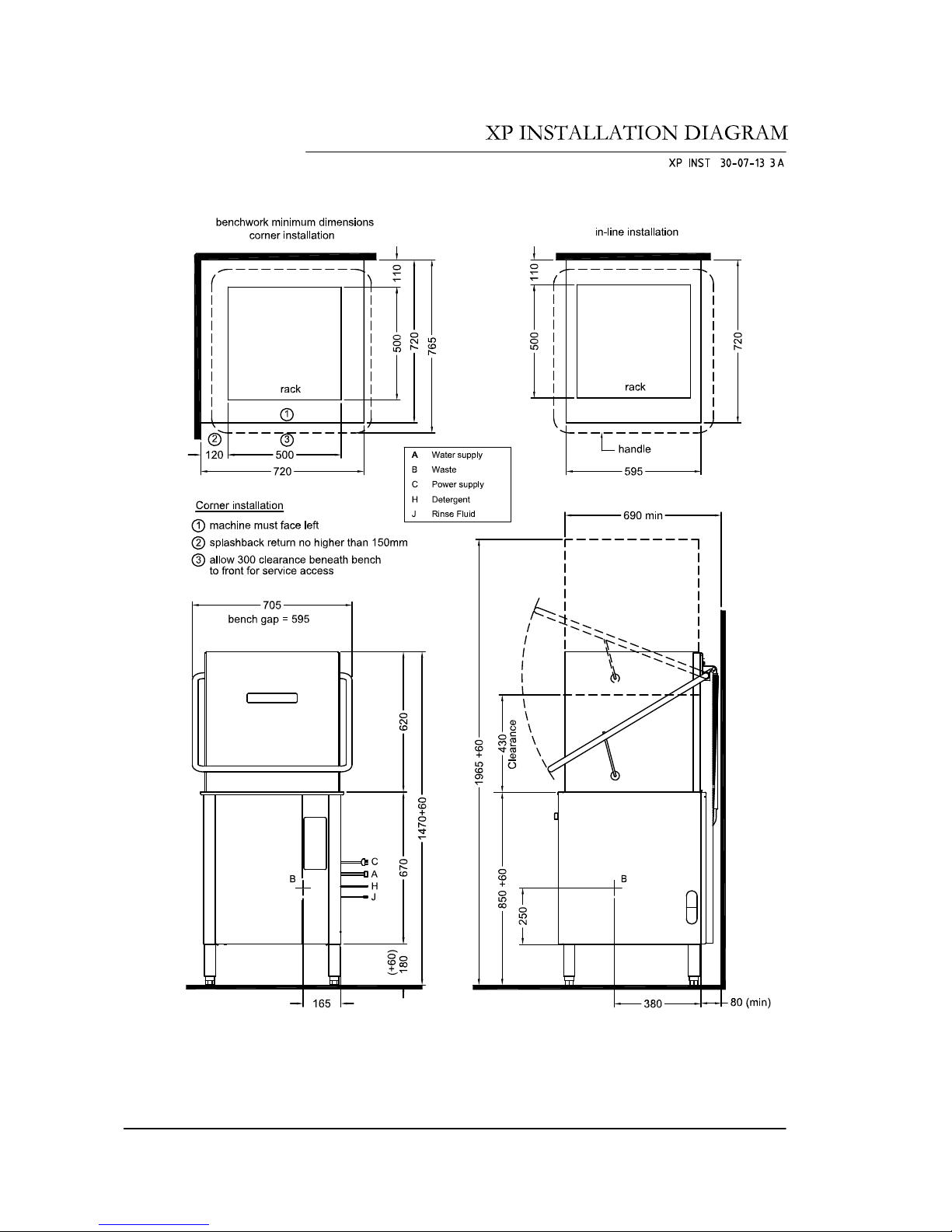
Refer Bench Details diagram.
In corner installations the front of the machine must face to the left of the corner.
In corner installations high or angled bench return off wall may clash with door handle.
Level and secure machine and benches. Adjust to ensure smooth travel of rack through
machine.
Water Supply
Hot water temperature 65°C ± 5°C
Connection 20 mm (3/4" BSP Male)
Flow rate minimum 20 litres per minute
Consumption per cycle 2.6 litres approximately
Backflow prevention DCV = Dual Check Valve fitted standard
Pressure 200-350 KPa = 30-50 Psi.
Above this range fit pressure limiter. Don’t use small diameter plastic supply lines especially
below this range when optional rinse booster pump may be required. FLUSH supply line
before connection. Poor quality supply or excessive water hardness may affect performance
or damage machine – filtration and/or softening is recommended.
Waste
40 mm gravity drain – refer point B on installation diagrams – run waste directly behind the
machine or through open base.
Power
15A 240V 50Hz via switched outlet adjacent to machine, which is supplied with cord set
including 15A plug. Machine may also be installed on 3 Phase, Neutral and Earth, 415V
50Hz 15A/ph, permanently wired via wall switch mounted adjacent to machine – refer
schematic diagram for this requirement.
Detergent
Insert detergent pump inlet hose into container of commercial low foam detergent. Open
machine door and switch machine on. Press and hold detergent prime switch behind front
cover until chemical flows into machine.
Rinse Aid
Insert injector inlet hose into rinse aid container. Check amount of fluid rising up inside
pipe during pulse at start of rinse cycle. Rotate adjusting screw clockwise to reduce flow
and anticlockwise to increase flow.
Installation Checklist
Complete attached Installation Checklist to ensure machine is installed and running
correctly, and operator is familiar with operating procedures.
Troubleshooting
If the machine doesn’t fill after switching on the power, check and ensure that the hot
water supply tap is open, water supply pressure is not below specification and Dual Check
Valve is not faulty and correctly installed (arrows on the dual check valve’s body specify
water flow direction).
!
Service Manual XP-2
5
Revision 1C
Page 6
Service Manual XP-2
6
Revision 1C
Page 7
Service Manual XP-2
7
Revision 1C
Page 8
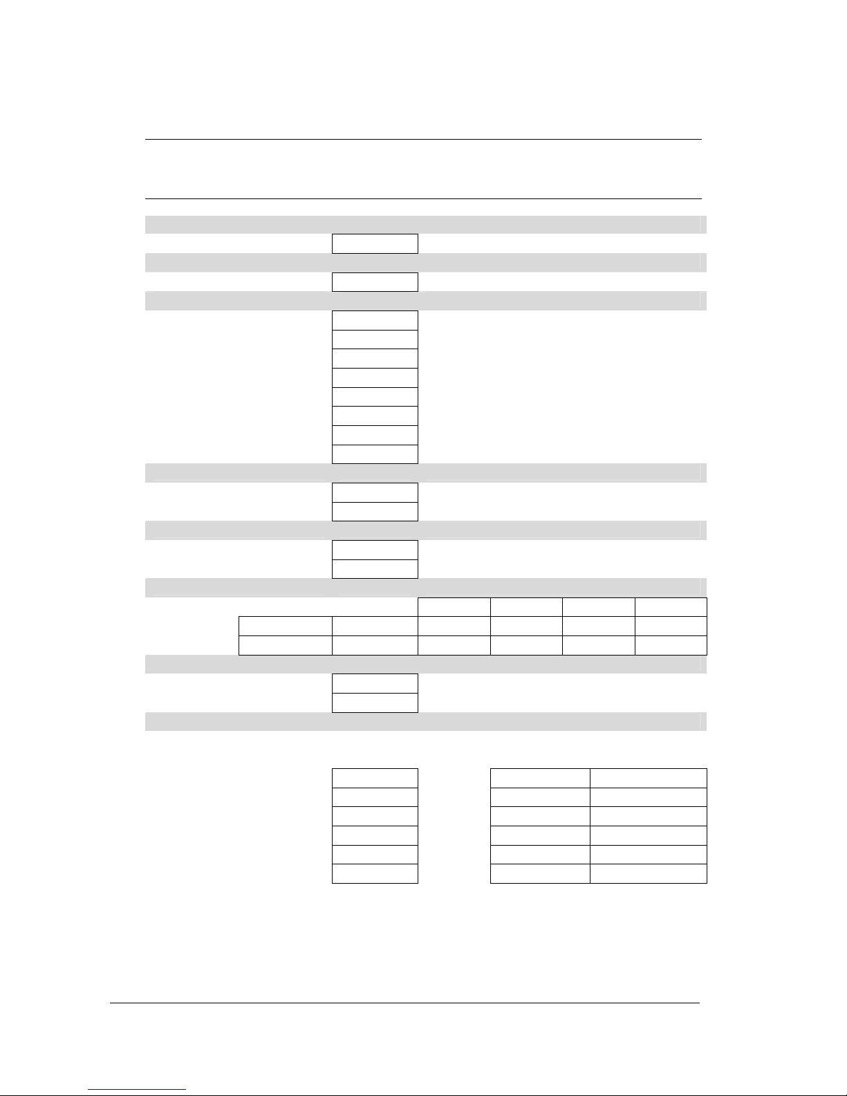
Installation Checklist
CHECK OK / NOTES
Delivery
Supplied complete no transit damage
Position
Level and stable on sound, waterproof, self draining floor
Water
Isolator valve fitted Accessible, all fittings sound, no leaks
DCVs fitted (Washtech only) Correct direction
Temperature 65 ± 5°C
Flow rate Minimum 20 litres per minute
Pressure 200-350 kpa, limiter fitted if above this range
Booster fitted if below this range
Cold water when required Pressure not above 350 kpa
Hardness Filter or softening if required
Power
Isolating switch Fitted, functional and accessible
Supply as specified Voltage, current, circuit breaker
Waste
Usually 40 mm Sound, no leaks
Air gap on pumped drain
Chemicals
product name container no leaks primed conc.OK
Detergent
Rinse Aid
Machine operation
Run several cycles
Confirm correct operation Including correct fill levels
Operator training
Confirm Operator has copy of Operator Manual and is familiar with procedures
Start-up Model / Serial
Pre-rinse and racking Owner
Machine operation Location
Drain Technician
Clean Date
Shut-down Signed
Service Manual XP-2
8
Revision 1C
Page 9
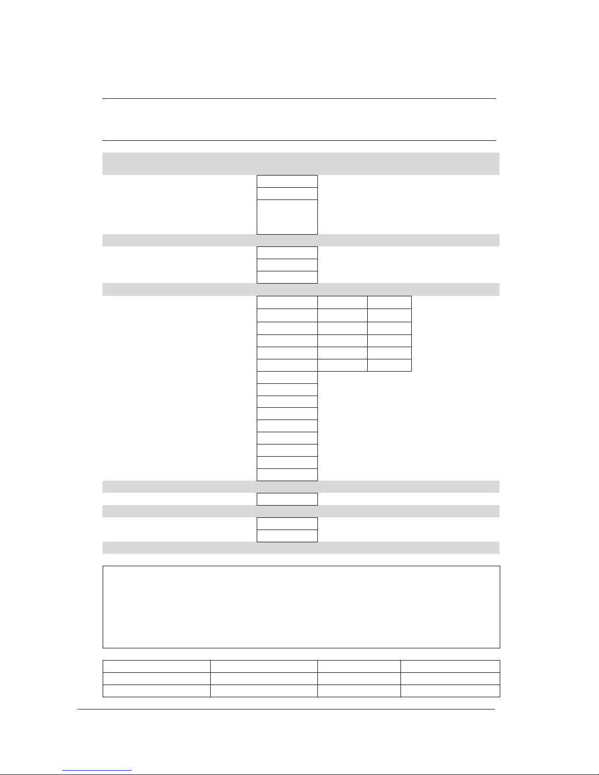
Maintenance Checklist
CHECK OK / NOTES
Installation – use Installation Checklist on previous page to check all services, operator training
and chemical issues
Services water, power, drain etc.
Operator trained / has instructions
Chemicals squeeze tube checked – replacement
recommended every 6 months,
product type, container, leaks etc.
General conditions
Cleanliness of machine daily maintenance
Presence of pests
Leaks
Operation
Temp °C Amps
Elements Wash 60
Rinse 83
Pumps Wash n/a
Rinse n/a
Drain functional n/a
Water Flow Wash arms and jets jets clear, good rotation, bushes OK
Rinse arms and jets jets clear, good rotation, bushes OK
Cycle Fill levels pressure switch settings
Drain operation upstand/pump
Noise sounds OK
Recovery between cycles
Controls Door switch including auto start if fitted
Switches, lights, gauges all sound and functional including door/s
Performance Wash and rinse effective
Electrical
Safety test if required
Cabinet
Door / Handle / Catch operational
Rack slide good rack entry / withdrawal
Comment / Action Required
Model / Serial Technician
Owner Signed
Location Date
Service Manual XP-2
9
Revision 1C
Page 10
Dishwashing Procedures for best results
Note: these are general instructions to assist in getting the best performance from Washtech dishwashers –
some comments and / or illustrations may not apply to every unit.
Installation
Read the Operator Manual. Correct installation, including an adequate supply of
water at the correct temperature and pressure is essential for effective operation of
your machine. Refer installation instructions for details. Drain hose outlet height
is important on some models. Always install on a sound self-draining floor.
Water softening is recommended in hard water areas - especially for glasswashing
Pre-rinsing
Pre-scraping of dishes is required by hygiene regulations.
The best method is to pre-rinse with a pre-rinse spray unit or alternatively by scraping or dunking in water.
Cutlery Procedures
Pre-soak cutlery in warm water, preferably containing cutlery
pre-soak compound - refer your chemical supplier.
Do not overfill cutlery containers. Cutlery should be loose with
handles down. Sort after washing rather than before. Cutlery
of only one type nests together and obscures wash water.
Racking Procedures
Do not overload racks, minimize the overlap
of crockery. Cycle times are short and water
consumption per cycle low - so there is no
advantage in overloading racks.
Cycle Times
For multi-cycle machine use the longest
cycle whenever possible. Note that water
consumption does not increase with
longer cycles. Only choose shorter, faster
cycles when necessary.
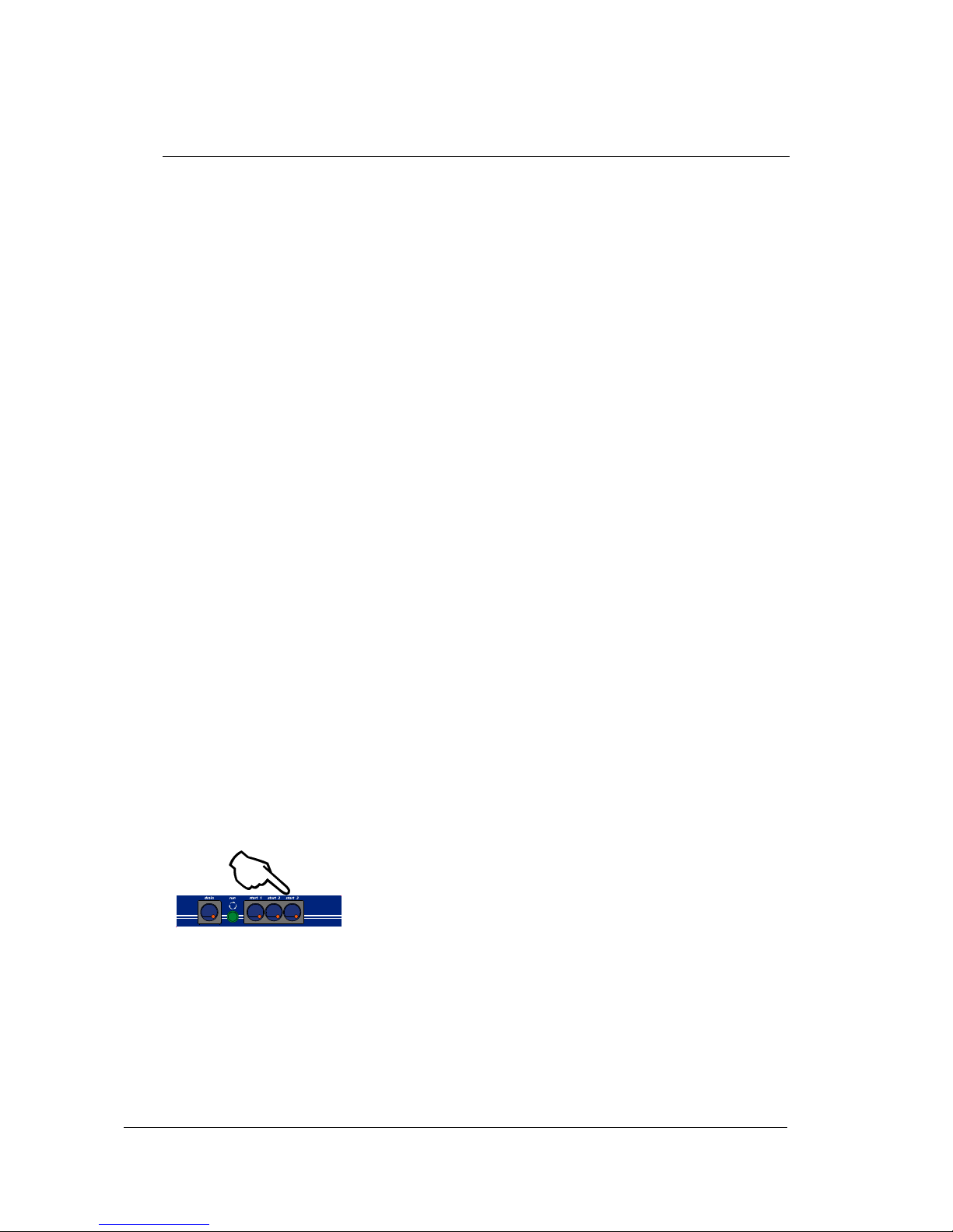
Detergent
Use of correct type and quantity of low foaming commercial grade
detergent is essential to the performance of the machine. We
strongly recommend that you use a professional dishmachine
chemical supplier - and will be pleased to recommend a supplier in
your region. Discuss with them the use of cutlery pre-soak
solution, detergent and drying agent.
Service Manual XP-2
10
Revision 1C
Page 11
Dishwashing Procedures for best results
Drying
Single tank commercial dishwashers do not have a drying
cycle. However, the machines do rinse at high temperatures
which promote fast drying particularly when drying agents are
used. We recommend prompt removal of the rack from the
machine - leave the rack on the bench for 2 to 3 minutes
before emptying. This time will be reduced with correct use
of drying agent (rinse fluid) which reduces water surface
tension and allows water to drain quickly from washware.
For advice on drying agents and injectors refer to your
chemical supplier.
Daily Cleaning
It is essential that the machine is drained and cleaned at the end of each day. Drain
the machine then remove, clean and replace filters as per the operating
instructions. Regularly check the wash and rinse jets and clean them if necessary –
see below.
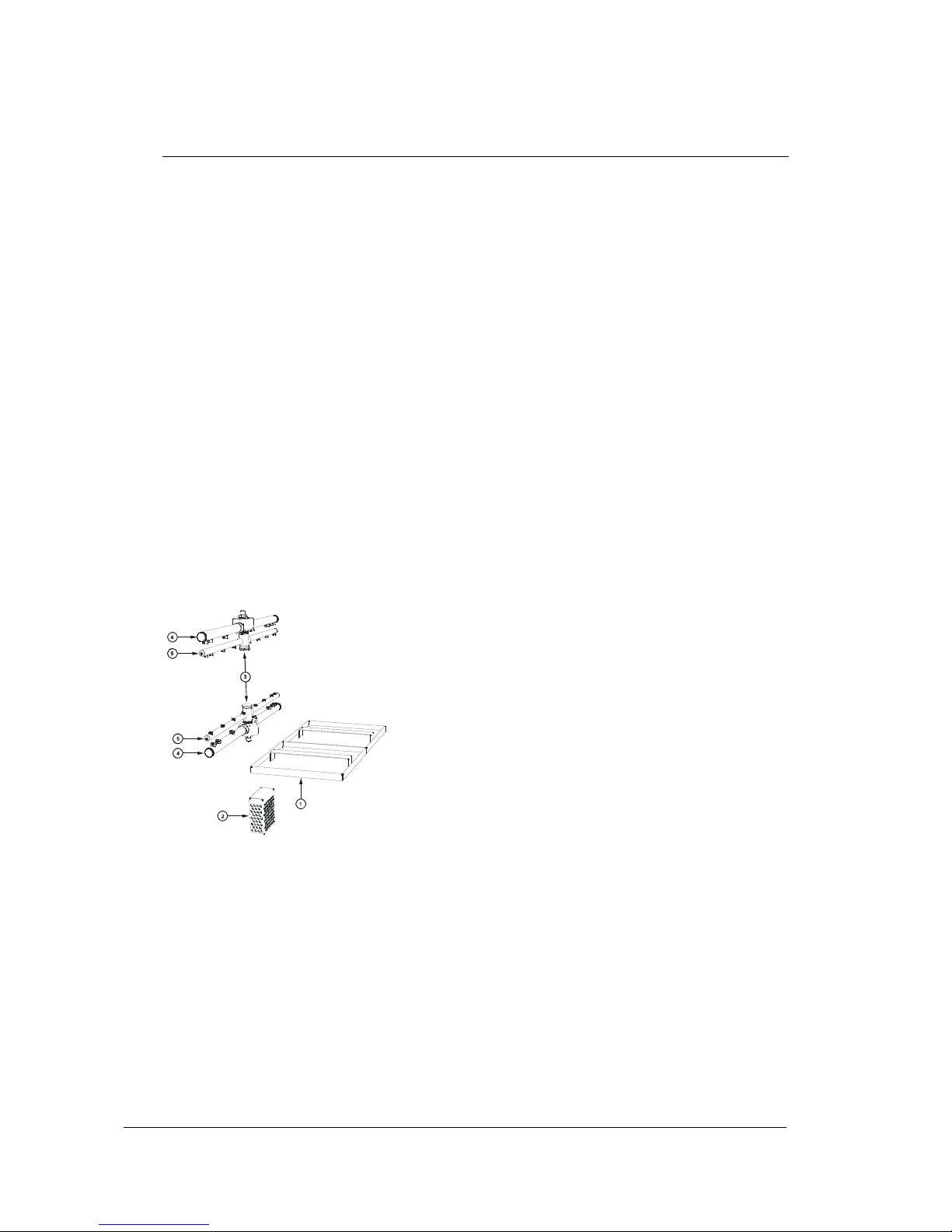
Regular Cleaning
Remove scrap trays and wash pump inlet filter, where
fitted, and rinse or brush clean.
Remove wash and rinse arms by undoing the central
thumbscrews. If necessary, remove the end cap screws
from the wash arms and the end screws from the rinse
arms and flush the arms with water and/or use a toothpick or
paperclip to clear jets.
Note: arms and filters vary with model and may appear
different from this illustration e.g. those models with plastic
wash arms have removable jets for ease of cleaning
Regular Servicing
Regular servicing is essential for optimum performance and
long machine life. Maintenance is recommended at least
once every six months – especially when chemical injectors
are fitted.
Please contact Moffat or your Authorised Service Provider
to organize regular servicing of the dishwasher - discuss a
Preventative Maintenance Agreement.
Note: these are general instructions to assist in getting the best performance from Washtech dishwashers –
some comments and / or illustrations may not apply to every unit.
Service Manual XP-2
11
Revision 1C
Page 12

Troubleshooting Chart
PROBLEM POSSIBLE CAUSES REMEDY (Check/Adjust/Replace)
Filling
Not filling Water supply valve shut Water supply valve
Door switch faulty Door switch
Solenoid valve faulty Solenoid valve
Rinse lines blocked Rinse pump, solenoid valve filter
Pressure switch faulty Pressure switch
Won't stop filling Solenoid valve faulty Solenoid valve
Pressure switch set too high/faulty Pressure switch
Pressure bell blocked, hose broken Pressure bell, hose, hose connections
Filling during Pressure switch refill level too high Pressure switch
wash cycle Upstand does not fit properly Drain upstand
Heating
Rinse not heating Over-temp thermostat tripped Over-temp thermostat, rinse element
Rinse thermostat settings or fault Rinse thermostat
Rinse element faulty Rinse element
Overheating Thermostat adjustment Thermostat
Thermostat probe out of pocket Insert & secure probe
Wash water cold Wash thermostat set too low Wash thermostat
Wash element faulty Wash element
Machine not rinsing Solenoid valve, water supply
Rinsing but not hot Thermostats & elements, water supply
Rinsing cycle too short Timer
Cycle start
Does not start Not up to temperature Give machine reasonable time initially
Rinse thermostat faulty Rinse thermostat
Door switch faulty Door switch
Cycle finish
Rinse doesn’t stop Solenoid jammed open Solenoid valve
Timer stuck Timer
Pressure switch faulty Pressure switch
Wash continues Timer jammed Timer / Timer motors
Cycle time
Cycle too long Timer faulty Timer / Timer motors
Cycles selection (for multi-cycle machines)
Time not changed Selector switch faulty Selector switch
Advance timer motor faulty 6 sec advance timer motor
Timer micro switches faulty T4 or T5 timer micro switches
Delays
At start or Rinse element faulty Rinse element
between Water supply cold Supply hot water
cycles Water supply pressure excessive Restrict supply pressure
Rinse cycle too long Timer
Service Manual XP-2
12
Revision 1C
Page 13

Troubleshooting Chart
PROBLEM POSSIBLE CAUSES REMEDY (Check/Adjust/Replace)
Drainage
Flooding Drain waste blocked Drain waste
Leaks
Leak from pumps Seal failure Pump seal
Leak from hoses Hose damage Hoses
Hose clamp loose Hose clamps
Splash from door Wash arm end caps missing End caps
Wash jets blocked Wash arm jets
Wash jets missing Wash arm jets
Arms not rotating Arms and bushes
Arms not level Arms
Wash Arms
Not rotating Wash jets not clean Wash jets
Arm bushes worn Bushes
Wash pump not working Wash pump
Rinse Arms
Not rotating Rinse jets not clean Rinse jets
Arm bushes worn Bushes
Water supply pressure low Water supply
Rinse pump not working (if fitted) Rinse pump (if fitted)
Noise
Noisy rinse cycle Rinse pump squeals Low pressure / blocked water supply
Noisy wash cycle Wash pump noisy Wash pump including inlet filter
Performance
Poor wash result Detergent not used Use quality low foam product
Detergent pump faulty Detergent pump
Squeeze tube to be replaced Detergent pump squeeze tube
Overloading racks Do not overload racks
Not pre-rinsing Use Fisher pre-rinse
Wash arms not rotating Remove and clean arms/check bushes
Wash jets blocked Remove arms and clean jets
Low wash pressure through arms Wash pump impellor
Wash temperature low Check wash /rinse heating
Excessive soiling Pre-rinse/use long cycle
Unrealistic expectation E.g. baked on soiling requires pre-
soaking
Poor rinse results Rinse jets blocked Remove arms and clean jets
Rinse arms not turning Remove arms, clean jets, check bushes
Poor racking procedures Do not overload racks
Excessive wash tank soil build up Pre-rinse, change wash water regularly
Not drying Poor wash/rinse performance Refer above
Low temperatures Check heating systems
Drying agent not used Use quality drying agent/rinse fluid
Service Manual XP-2
13
Revision 1C
Page 14

XP Operating Instructions
Start up
Fit drain upstand, wash pump filter,
scrap tray and shut door.
Turn wall power switch on and select
any cycle (1, 2 or 3).
Power light glows red and machine
fills automatically.
Wash Ready light (water symbol)
glows amber when wash tank is
ready.
Rinse Ready light (tick symbol) glows
amber when the machine is up to
required temperature
.
Operation
Select required cycle (1, 2 or 3 for
1, 2 or 3 minute cycle accordingly).
Try cycle 3 initially and switch to
faster cycles only if necessary.
Load rack into machine and close
door to start the machine.
Cycle light glows green while
machine operates.
When Cycle light goes out, cycle is
complete
NOTE: Machine might operate
longer than specified above if hot
water supply temperature is below
required.
After removing rack from
machine, DO NOT shut door as
machine will start up again.
Shut down every night
Turn machine and wall power switches off.
Remove drain upstand to drain wash tank.
Remove scrap tray and wash pump filter and rinse clean.
Replace drain upstand, filter and scrap tray.
Service Manual XP-2
14
Revision 1C
Page 15

Components
WARNING
All service/repair work must be carried out by qualified personnel only.
Location and Access
1. Rinse Tank
2. Rinse Safety Thermostat
3. Rinse Heating Element
4. Test Switch
5. Detergent Pump
6. Rinse Thermostat
7. Wiring Tray
8. Detergent Prime Switch
9. Door Switch Relay
10. Heating Contactor
11. Timer
12. Power/Chemical Terminal
13. Dual Check Valve
14. Fill/Rinse Solenoid Valve
15. Wash Pump
16. Pressure Switch
17. Door Switch
18. Wash Thermostat
19. Rinse Aid Injector
20. Wash Heating Element
21. Temperature Gauges
22. Control Panel Assembly
23. Indicator Lights
24. Power/Selector Switch
Service Manual XP-2
15
Revision 1C
Page 16
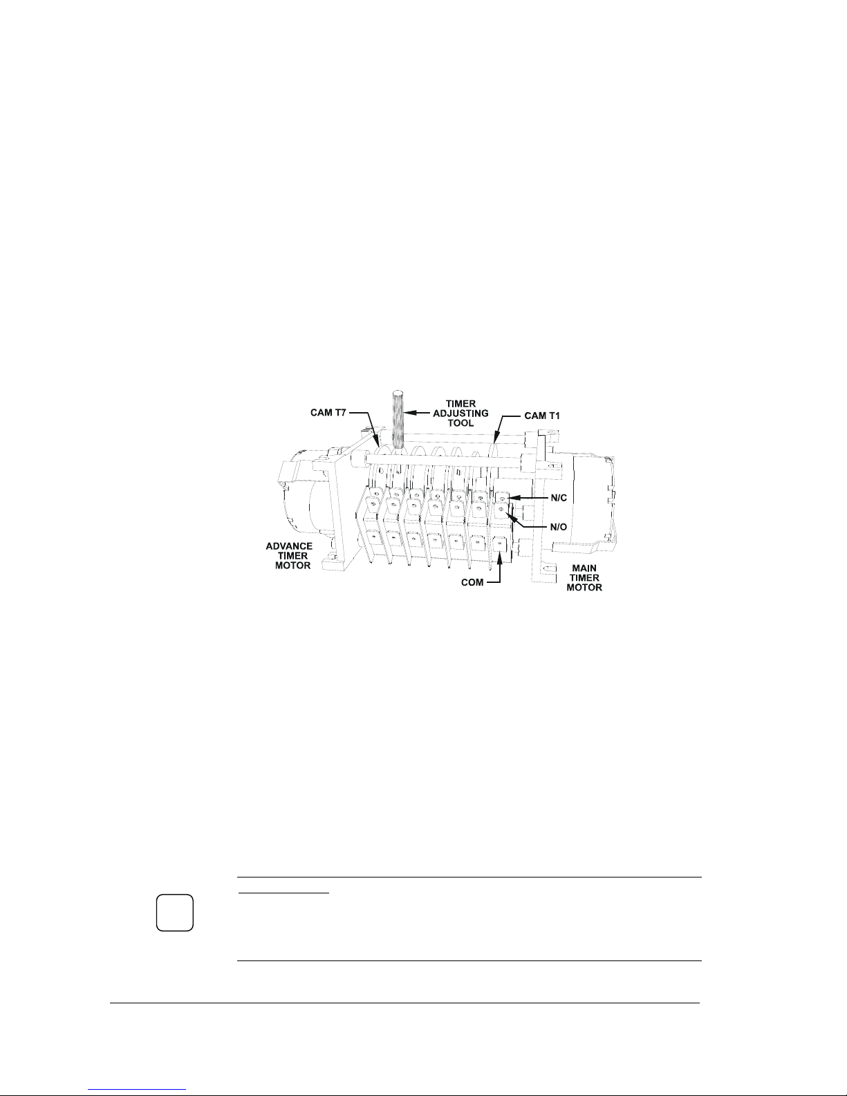
Timer
Part Number
32822
Function
Provides an automatic timing sequence of the wash, rinse, detergent and rinse aid injection
stages in a dishwashing cycle.
Description
The electromechanical timer has a main drive motor and gearbox which produce a full
rotation of the seven cams in 180 seconds. The advance motor and gearbox speed the
rotation of the timer to produce shorter cycles of 60 and 120 seconds. The timer cams
operate individual changeover switches in sequence during the rotation. The cams are
numbered from the main motor end. T1 controls the main motor, T2 – wash pump,
T3 – rinse solenoid, T4 – rapid advance motor for 60s cycle, T5 – rapid advance motor for
120s cycle, T6 – detergent injector if fitted, T7 provides thermostop function.
Diagram
Replacement
To replace the timer take note of the position of each connection, preferably on paper.
Disconnect all wires and remove the timer from the tray. Compare the cam setting of the
old and new timer to ensure that special settings are duplicated. Fit new timer taking care to
locate cam T1 in the same relative position. Reconnect the wires ensuring that no
termination is under strain. Test the machine to confirm correct operation.
Adjustment
The timer cams T2, T3, T6 and T7 are adjustable. The time settings on these cams can be
increased by making the gap in a cam wider, or reduced by reducing the gap. Use a timer
adjusting tool, supplied with the machine to modify a gap in the timer cams.
NOTE:
To increase (or decrease) detergent injection time adjust only the red
sector of the cam T6. The yellow sector sets the beginning of the detergent
injection at the start of the shortest wash cycle. If injection time is extended by
yellow sector adjustment it will be skipped on fast cycles.
IMPORTANT
The factory setting of the cam T3 allows for a 12 sec hot rinse. Reduction of this
time is prohibited by Health regulations. Extending this setting will increase hot
water consumption of the machine and may result in delays between the cycles as
this additional water is heated.
!
Service Manual XP-2
16
Revision 1C
Page 17
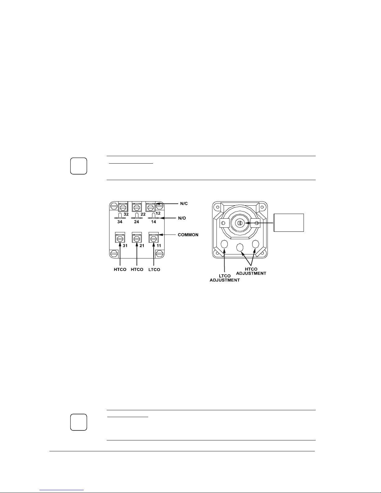
Rinse Thermostat
Part Number
3020
Function
Controls the rinse heating elements and prevents operation of machine if the rinse
temperature is below that required.
Description
The rinse thermostat is a specially calibrated 3 pole capillary type temperature operated
device. The thermostat does not have a control knob and it is factory set to the
temperatures required by Hygiene Regulations. The first pole’s LTCO changeover contact
is set to operate at 83 ±3°C, the other two poles HTCO contacts are set to 90±3°C.
Switching capacity: 16(4) A 380 V.
IMPORTANT
Do not break the seal or attempt to adjust the central multi pole adjusting screw
that is sealed with red compound.
Diagrams
LTCO – Low Temp Cut Out
HTCO – High Temp Cut Out
Replacement
Take note of the connections to the wiring loom before disconnecting. Remove the
capillary bulb from the rinse tank pocket. Select a new thermostat and carefully unwind
enough capillary to reach from the pocket to the thermostat mounting position. Carefully
position the tube with no kink or stress on the tube, also have due regard for the protection
of the tube against contact with live electrical terminals – secure or insulate as appropriate.
Adjustment
The thermostat is factory set to the specified above settings and it should not
normally be adjusted. If you are sure adjustment is required,
remove the grey tape
covering three adjusting screws for LTCO and HTCO settings (one or both HTCO poles
are used depends on model – check which HTCO terminals are wired before making
adjustments). Insert the thermo junction into the rinse tank pocket for the machine’s
temperature gauge. Energize the elements and check all temperatures on temperature rise.
Clockwise rotation of the screws increases the setting, anticlockwise – decreases it. Every
half turn of the adjusting screw changes the settings by approximately 6 degrees.
IMPORTANT
To make adjustments to the thermostat you will need a good quality thermometer
fitted with a “type K” thermo junction. The use of a stainless steel probe is not
permitted as slow response time in the device will cause inaccurate settings.
!
DO NOT
TOUCH
!
Service Manual XP-2
17
Revision 1C
Page 18
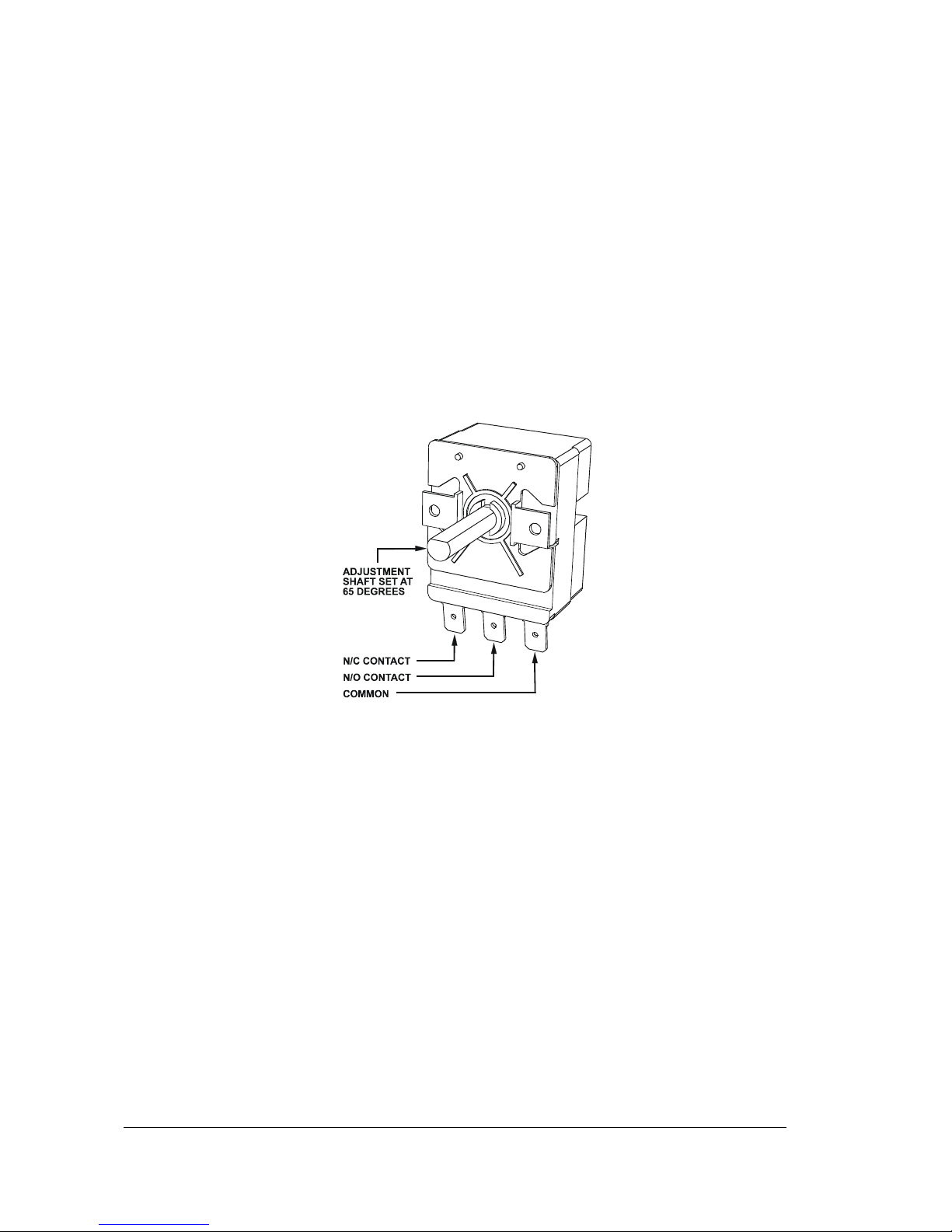
Wash Thermostat
Part Number
30201
Function
Controls the wash element
Description
The wash thermostat is a single pole capillary type device. It has a single changeover contact
and a rotating shaft for a manual temperature adjustment.
Factory default setting is 65°C.
Contact switching capacity: 16(4) A 380 V.
Diagram
Replacement
Drain the wash tank. Take note of the connections to the wiring loom before
disconnecting. Release thermostat’s gland nut, move the capillary bulb out of the mounting
bracket inside the tank and remove the bulb from the wash tank (remove the probe from
the pocket in the wash tank on the models supplied with a pocket for the thermostat
probe). Replace in reverse order.
Adjustment
Insert the probe of a digital thermometer into the wash tank. Check the thermostat settings
on a temperature rise. Adjustment is performed by rotating the adjustment shaft of the
thermostat. Clockwise rotation of the shaft increases the setting, anticlockwise– decreases it.
NOTE: the adjustment shaft in a flat horizontal position is a factory default setting
corresponding to 65°C (see the diagram).
Service Manual XP-2
18
Revision 1C
Page 19
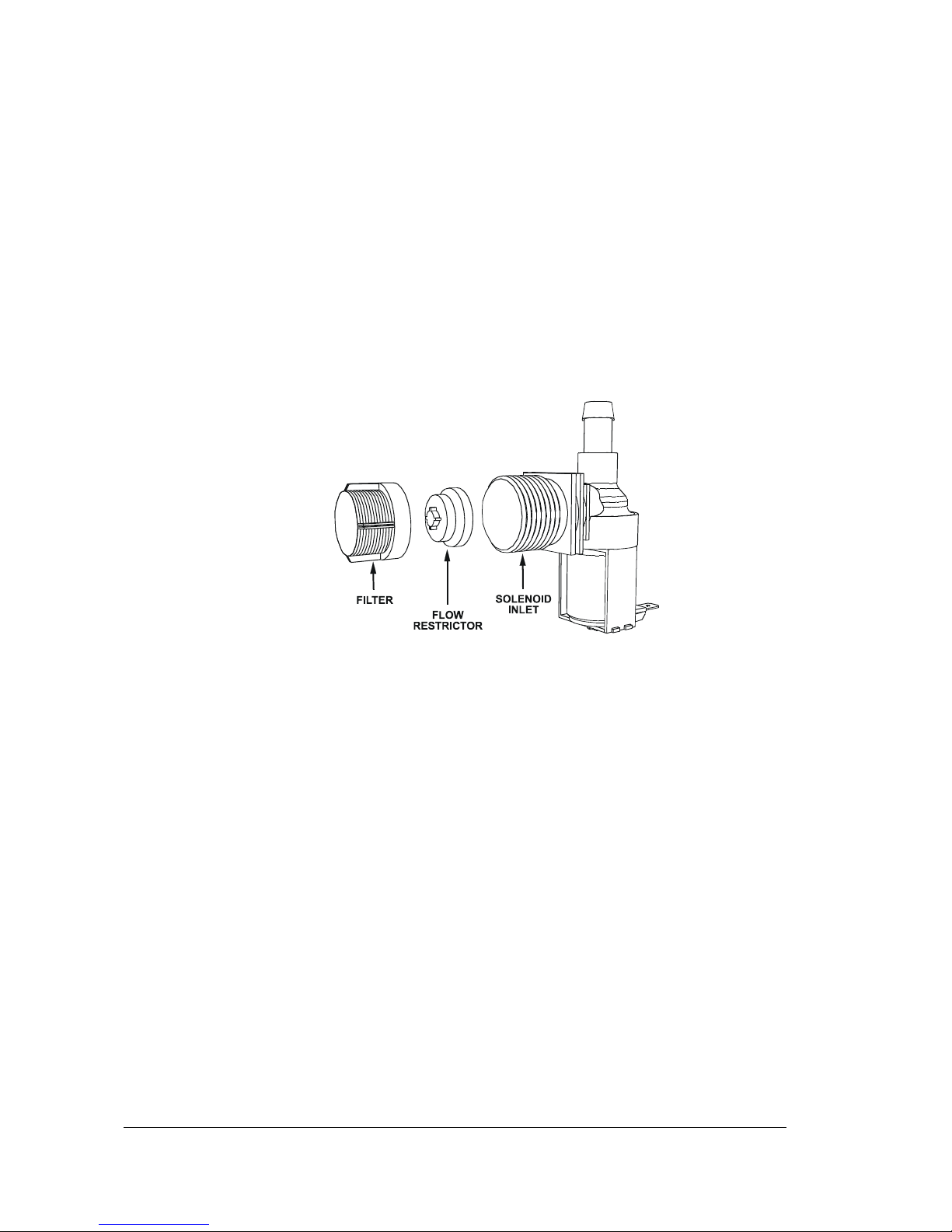
Solenoid Valve
Part Number
3342
Function
Controls flow of water into machine during filling of wash tank and final
rinsing.
Description
Electromagnetically operating water valve for use with cold and hot water.
Diagram
Replacement
Disconnect the wires from the solenoid connectors.
Remove hot water supply hose.
Release a hose clamp on the outlet solenoid hose and remove the hose.
Slide the solenoid valve up off the mounting bracket.
Replace in reverse order.
Adjustment
Remove the flow restrictor for installations with flow rate of hot water supply below 20
litres per minute.
Service Manual XP-2
19
Revision 1C
Page 20
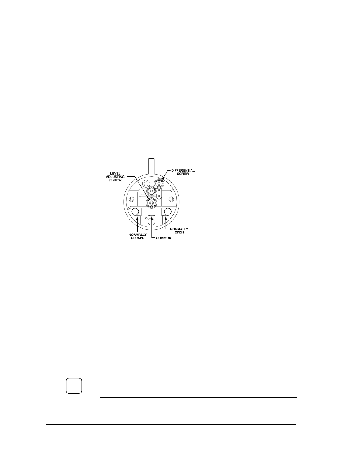
Pressure Switch
Part Number
600 30308
Function
Controls filling of wash tank and protects wash elements.
Description
The pressure switch is attached to the pressure bell. As the water level in the wash tank
rises air is trapped in the bell and increasing pressure is transmitted to the pressure switch.
When the tank is full the pressure switch shuts off the fill solenoid valve and switches on
the wash element. It allows a water level differential so that the tank level may drop with
the operation of the wash pump, without causing refilling of the machine.
Diagram
LEVEL ADJUSTING SCREW
CW rotation increases upper level
setting
DIFFERENTIAL SCREW
CW rotation increases
differential and reduces lower
level settings
Adjustment
Before making any adjustments drain wash tank, remove pressure tube from pressure bell,
blow gently into tube to check switching of pressure switch and then fit tube back.
Turn the power switch on, machine should start to fill. The machine should cease filling
when the water attains a level about 10mm below an overflow level of the upstand. Adjust
fill level if necessary by Level adjusting screw on the pressure switch.
Remove drain upstand to begin draining the wash tank. Fit back the upstand when Wash
Ready light goes off and measure the refill water level. A refill level should be set 10-20mm
above the wash element. Adjust if necessary by Differential screw on the pressure switch.
Close door to refill the wash tank and re-check the fill level.
Replacement
To remove the switch take note of the electrical connections and remove the wires. Slide
the switch from the mounting bracket and remove the rubber tube from the switch
connector. Replace in reverse order. Whilst in the process of replacing the pressure switch,
ensure that the pressure tube is in good order and clear of obstruction.
IMPORTANT
Ensure the tube from the air bell always goes up to the pressure switch.
Do not use thin wall vacuum tube for replacement.
!
Service Manual XP-2
20
Revision 1C
Page 21
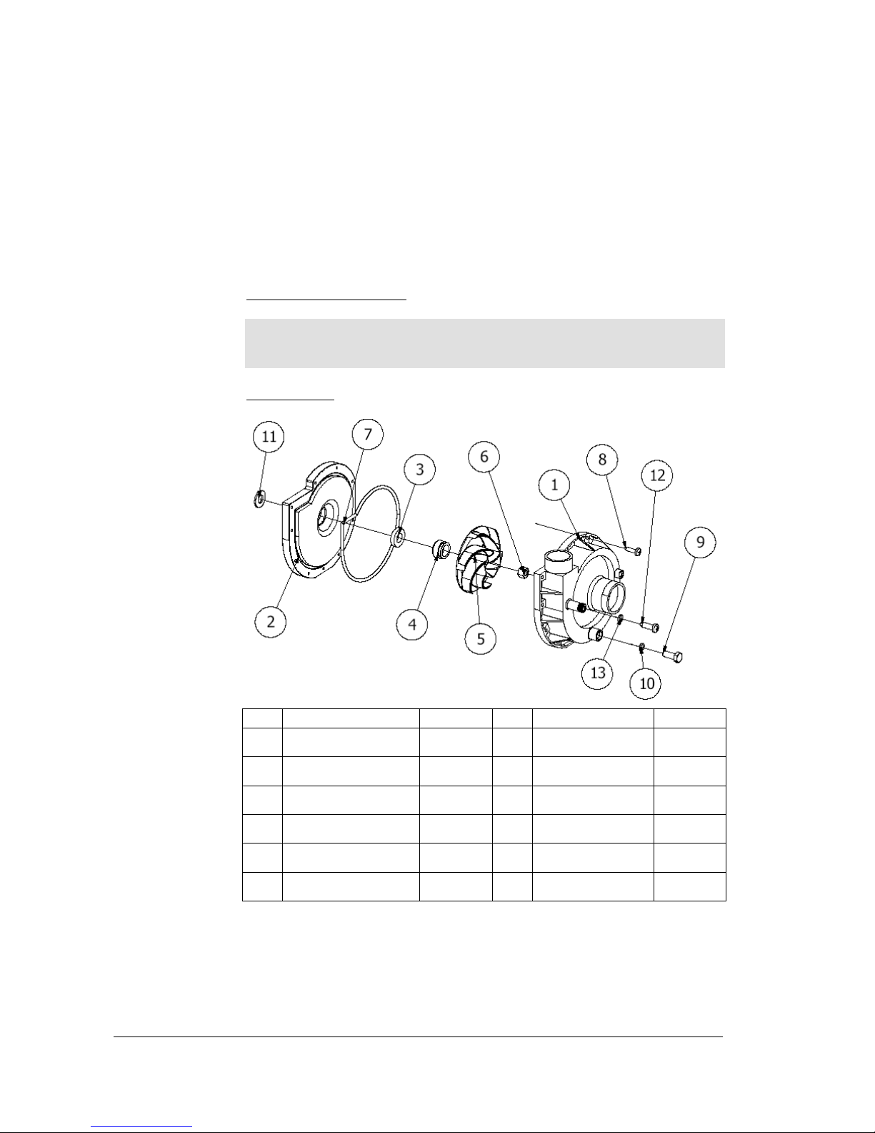
Wash Pump
Part Number
600 30299
Function
Pumps water from the wash tank to the wash arms providing a recirculating wash
cycle.
Description
Electric Pump ZF 320V SX
Power: HP 0.93 Kw 0.68
Voltage: 230 V 50Hz
Amperes: 3.0 A
Capacitor: 12.5 uF
Speed 2800 rpm
Protection: IP 20
Hm Min: 1.0 m
Hm Max: 12.3 m
Diagram
Hydraulic parts
ITEM DESCRIPTION PART # ITEM DESCRIPTION PART #
1 Volute 600 41116 7 O-ring 600 41113
2 Pump flange 600 41117 8 Screw 3 Fixed seal 600 41110 9 Plug screw 4 Rotating seal 600 41111 10 O-ring plug 5 Impeller 600 41115 12
Screw hose
connector
-
6 Nut 600 41112 13
O-ring hose
connector
-
Replacement
Drain the wash tank and switch off the power.
Disconnect the wires from the pump connectors and the pump capacitor. .
Release the hose clamps on the inlet and outlet pump hoses and remove the pump.
Replace in reverse order.
Service Manual XP-2
21
Revision 1C
Page 22
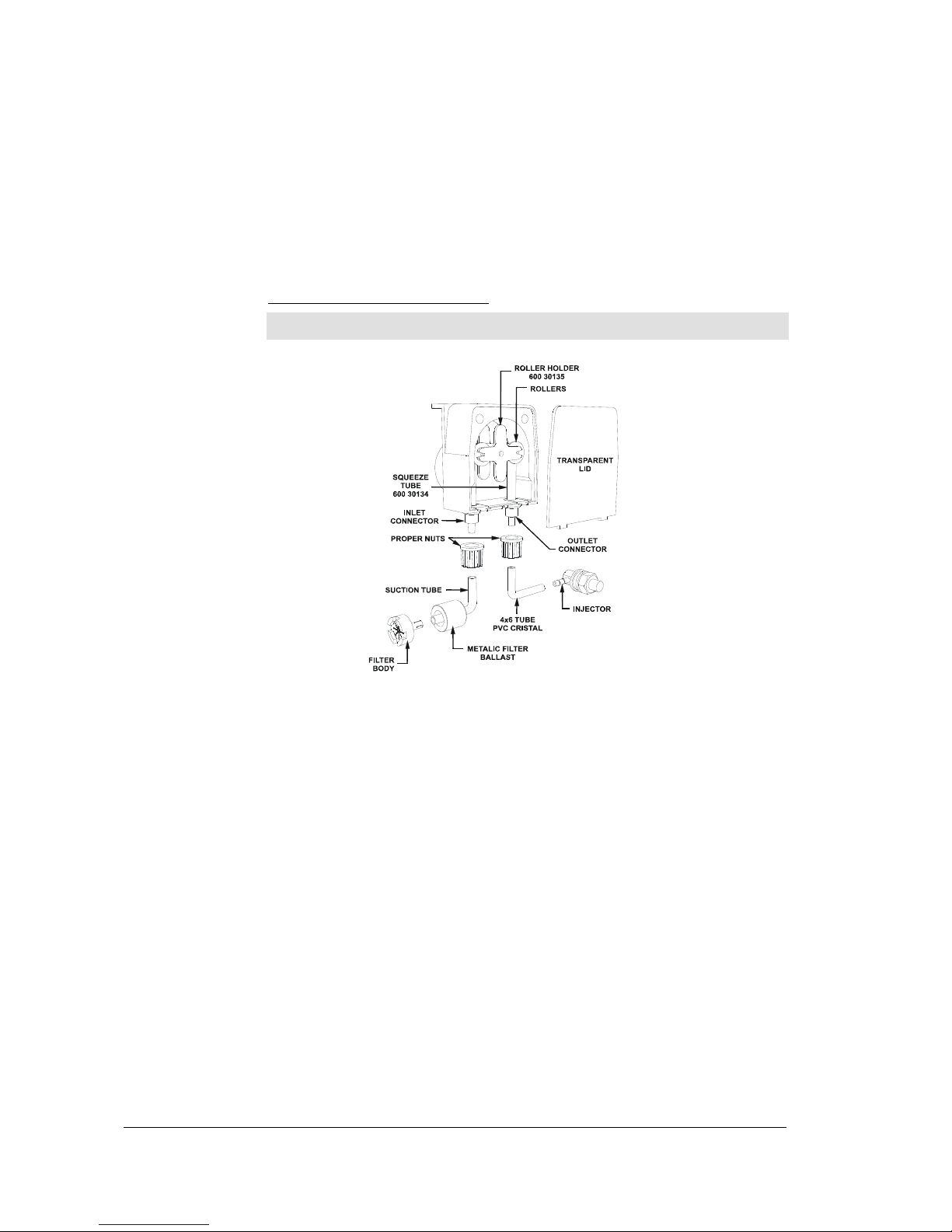
Detergent Pump
Part Number
600 30094
Function
When fitted the pump automatically injects detergent into wash tank during filling
of the machine and at the start of each wash cycle.
Description
Fixed Flow Peristaltic Pump PG1.5
Voltage: 230 V 50Hz
Pressure: 0.1 Bar
Flow rate: 1.5 L/h (0.42 ml/sec)
Max suction height: 1.5 M
Diagram
Replacement
Peristaltic pumps provide reliable and accurate detergent dosing. However over
time the squeeze tube in the pump will flatten and become ineffective, and/or split
and leak. We therefore recommend quarterly inspection of the squeeze tube and
replacement every six months in high use situations, particularly when chlorinated
detergents are used.
Adjustment
Standard machine controls operate the detergent pump continuously during filling
of the wash tank. At specified water supply pressures the fill flow is about 12l/min.
The detergent pump dispenses at a rate of 25 ml/min, i.e. the pump is dispensing
2 ml. of detergent per litre of wash water during filling.
The detergent pump is also set to operate during the wash cycle. Factory timer
settings in seconds of pump operation per wash are: XG – 10 sec,
GLV/UD/XP/XU – 15 sec, AL/AL8/PW1/TW – 20 sec, PW2/PW3 – 30 sec.
These settings will deliver about 2 ml of detergent per litre of rinse water
consumed. If the recommended concentration of your detergent is different from
2 ml/litre then the dosing time should be adjusted – refer Timer page in the
Service Manual for instructions. The dosing time T = 2.4 V x C, where V is the
volume of water consumed by the machine per cycle – refer Installation
instructions, and C is the required concentration of your detergent. For example, if
water consumption per cycle is 3 litres and recommended concentration is
3 ml/litre then the dosing time should be adjusted to 22 seconds.
On glasswashers where cold final rinse is used longer injection times are required
to compensate for the dilution of wash water by the cold rinse.
Service Manual XP-2
22
Revision 1C
Page 23
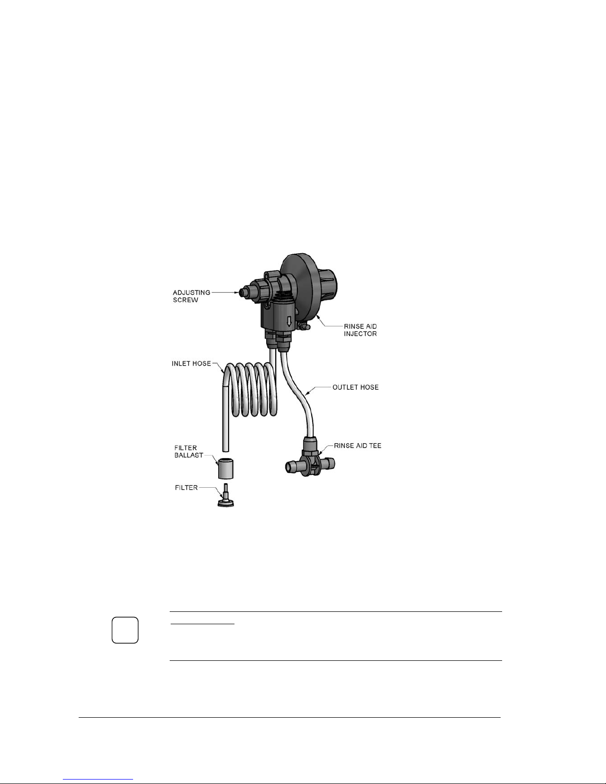
Rinse Aid Injector
Part Number
600 30324
Function
Adjustable flow rate hydraulic rinse pump for rinse-aid chemical dosing
Description
The injector works by using the water pressure in the rinse line. The pressure in
the input line causes the suction of a determined amount of chemical for each
cycle. At the end of the cycle a spring injects the chemical in the rinse pipeline.
The flow rate is adjustable from 0 to 3cc/pulse.
Diagram
Adjustment
Insert injector inlet pipe into the rinse aid fluid container. Run the machine. Check
the amount of the fluid rising up inside the pipe during the pulse at the start of the
rinse cycle - a 75 mm rise within the tube approximately corresponds to the
volume of 1 mls of rinse aid fluid per cycle.
Rotate Adjusting screw clockwise to reduce flow and anticlockwise to increase
flow. Every turn of the adjusting screw will increase/decrease the dose of rinse aid
fluid by 0.4 ml more/less.
IMPORTANT
If the rinse aid injector does not appear to be working turn in adjustment screw
clockwise until fully closed and then unscrew (about 6 turns anticlockwise) until
the injector begins to operate.
The volume of rinse aid fluid will depend on factors such as product type, water
hardness etc., but typically 0.5ml per litre of water is required – refer Installation
instructions for the volume of rinse water consumed by the machine per cycle.
!
Service Manual XP-2
23
Revision 1C
Page 24
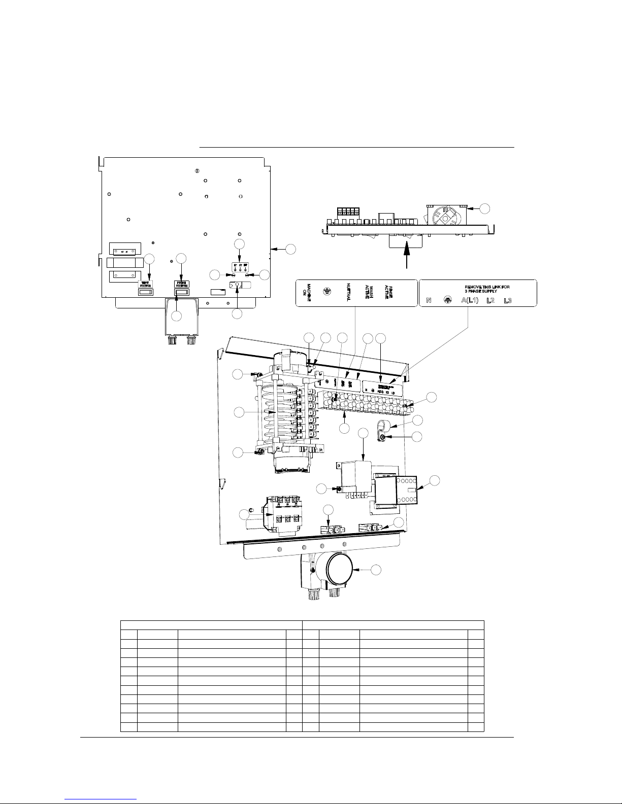
PLAN
A
PERSPECTIVE VIEW
Parts List
ITEM PART NUMBER DESCRIPTION QTY
1 32822 TIMER4907DV(180/6 SEC)3 CYCLE 1
23035
SWITCH SINGLE POLE BIASED BLACK
2
3 8816 MS RH BRASS 3/16 X 3/4 1
48151
NUT HX BRASS 3/16" PRESSED
1
5
3229 TERMINAL STRIP 12 WAY 1
63020
3 POLE THERMOSTAT
1
7 8800 MS PAN POZI ZP M4x6 2
8 600 30131 P CLIP 20.8mm 1
9 8801 MS PAN POZI ZP M4x12 5
10 326 10216 M2 (3) WIRING TRAY SUB ASSEMBLY 1
Parts List
ITEM PART NUMBER DESCRIPTION QTY
11 REF LABEL TEST SWITCH 1
12 8802
MS PAN POZI ZP M4x25
2
13 600 80052 MS RH ZP M3x6 2
14 REF
CHEMICAL CONNECTIONS LABEL
1
15 REF POWER CONNECTIONS LABEL 1
16 600 30223
JQX-12F POWER RELAY
1
17 Label LABEL THERMOSTAT ADJUSTMENTS 1
18 600 30337 CONTACTOR 20A 3NO/NC 230-240V 1
19 600 30094-2 PERI PUMP 1.5L/H SEKO-KIT 1
20 REF LABEL PRIME SWITCH 1
A
208 10046 23/09/2013
3-A
XP WASHTECH WIRING TRAY ASSY
REV
Assembly Diagrams
1
2
1
7 7
8
9
11
10
9
9
6
31212
6
14
15
16
2
13
5
18
17
19
20
2
4
Service Manual XP-2
24
Revision 1C
Page 25
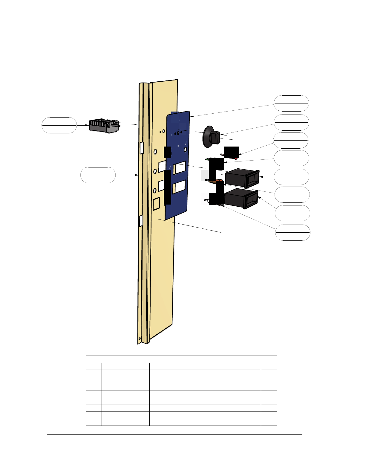
EXPLODED VIEW
Parts List
QTYDESCRIPTION
PART NUMBERITEM
1XP (3) CONTROL PANEL 208 200061
1XP CONTROL LAB EL208 700012
2
TEMP GAUGE RECTANGULAR 58x25
600 900803
1
LENS & NEON ASSY (GREEN) 12mm
600 301634
1LENS & NEON ASSY (RED) 12mm600 30161
5
2
LENS & NEON ASSY (AMBER) 12mm
600 301626
1
KNOB SELECTOR SWITCH
600 30467
7
1SWITCH 4 WAY QUICK CONNECT600 302698
208 10045 26/09/2013
3-A
XP CONTROL PANEL ASSY
REV
7
600 30467
2
208 70001
5
600 30161
4
600 30163
3
600 90080
3
600 90080
6
600 30162
6
600 30162
8
600 30269
1
208 20006
Service Manual XP-2
25
Revision 1C
Page 26
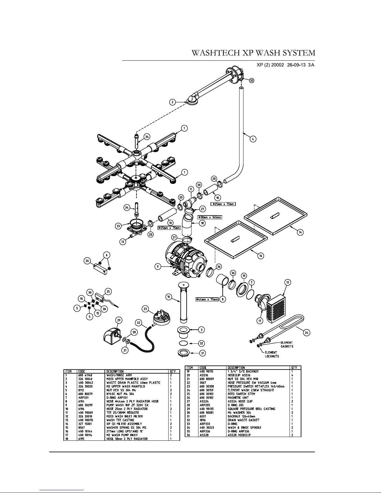
Service Manual XP-2
26
Revision 1C
Page 27
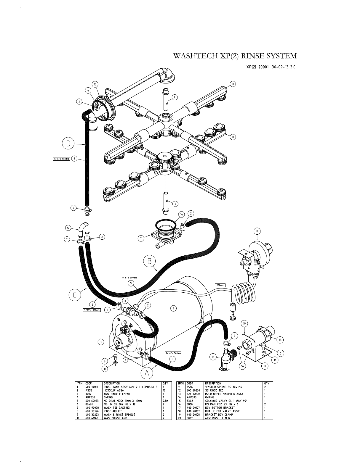
Service Manual XP-2
27
Revision 1C
Page 28
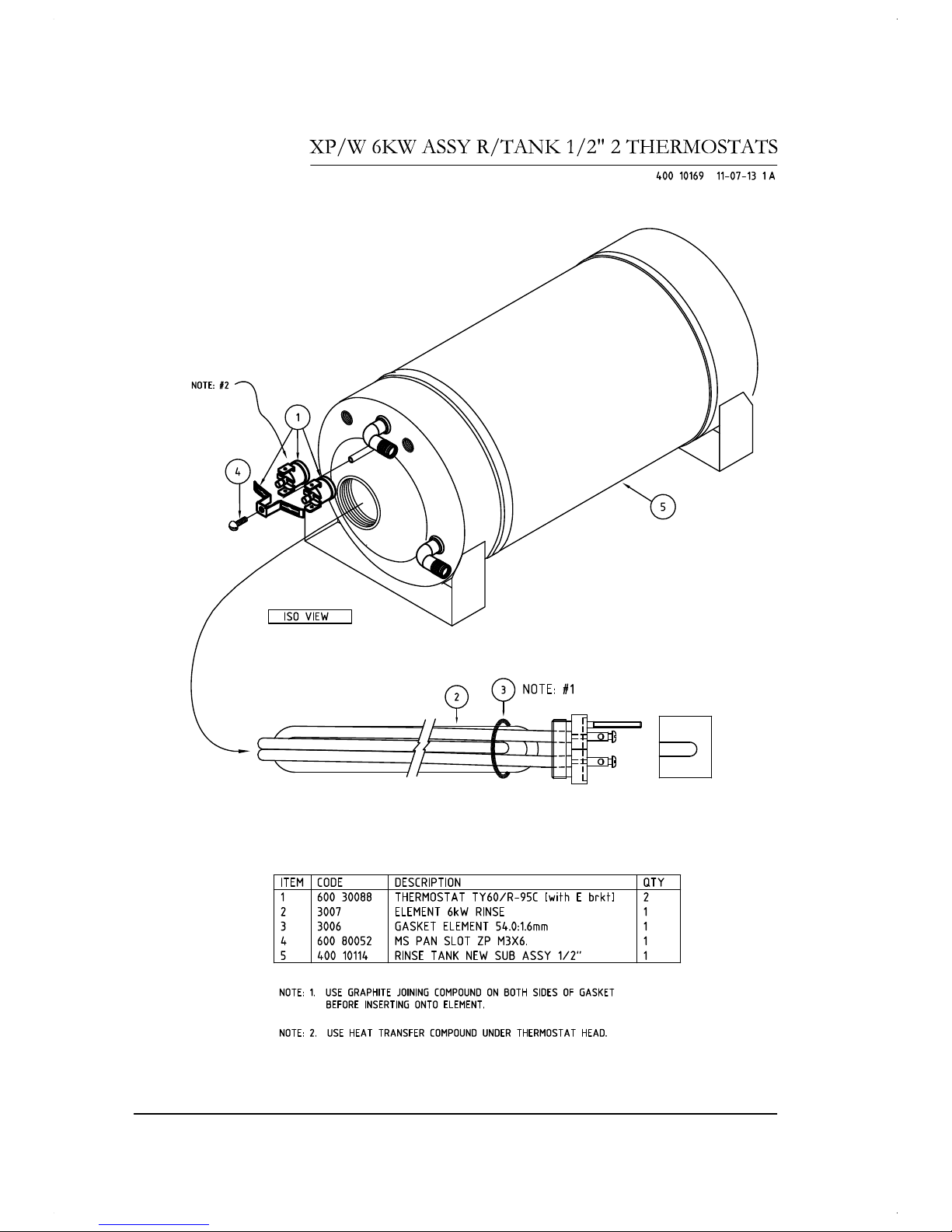
Service Manual XP-2
28
Revision 1C
Page 29
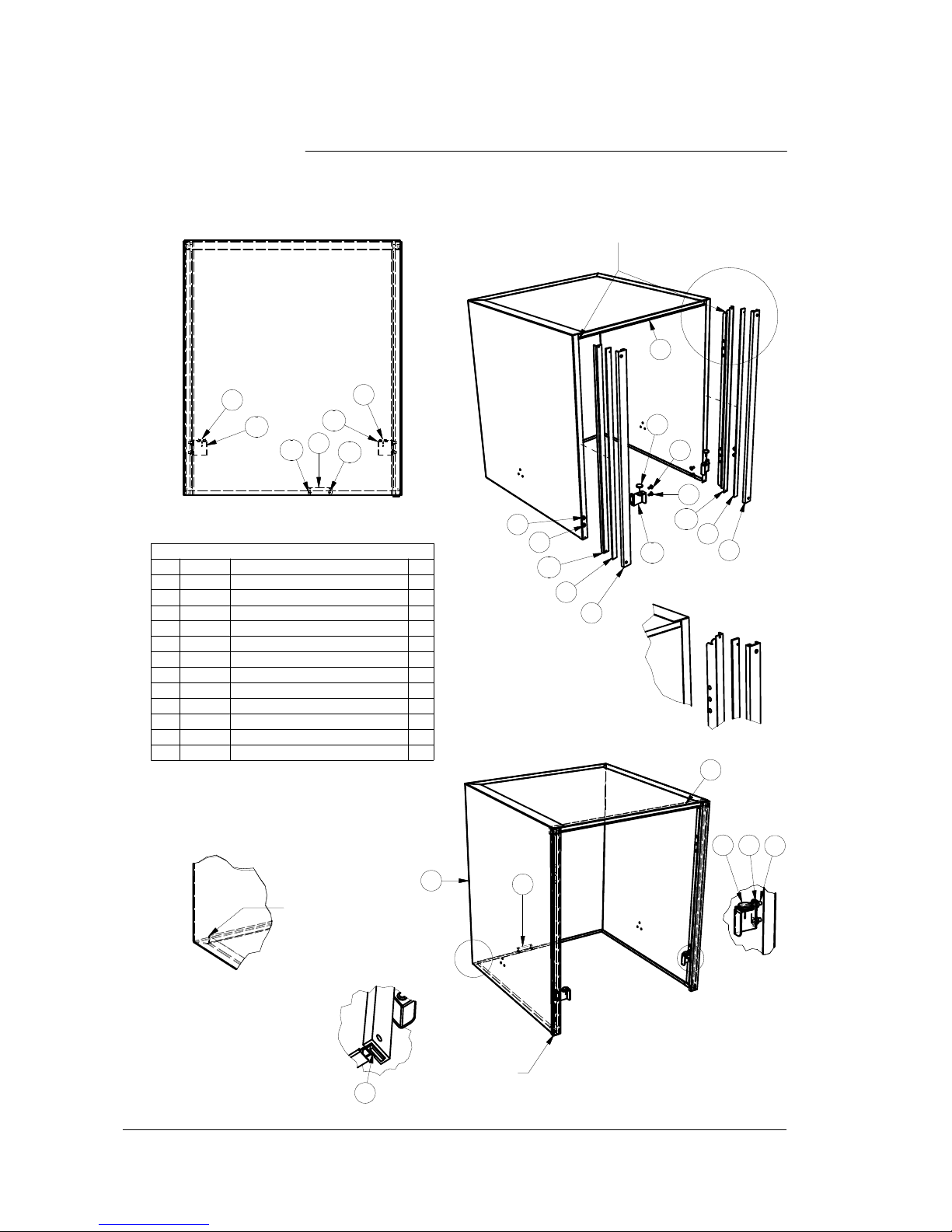
EXPLODED PERSPECTIVE VIEW
A
PERSPECTIVE VIEW
B
C
FRONT VIEW
A
Parts List
QTYDESCRIPTIONPART NUITEM
1M2 (3) DOOR326 200251
1
M2(3) DOOR UPPER INFILL
326 200242
2
M2 DOOR SLIDE
326 300043
2M2(3) DOOR STRIP SPACER326 20007
4
4HANK BUSH 304 SS M5600 80016
5
4M5 x 12 SS TRUSS HEAD SCREW600 800176
2
ANTI RATTLE BUTTON
18257
1
MAGNET
600 301828
2AL(3) DOOR BACK RAIL SUPPORT351 2007410
1M1(3) DOOR STOP BRACKET (LH)301 2000911
1
M1(3) DOOR STOP (RH)
301 2003512
2
SCREW 6g 12mm T304 SS SELF TAP
600 8005927
B
D
326 10007
9/02/2010
3-H
M2 (3) PASS-THROUGH DOOR ASSY
REV
1
2
10
DETAIL C
4
SPOT WELD TOP ONTO DOOR FIRST AND
APPLY A BEAD OF SILICON SEALER TO
THE INSIDE CORNER
3
INNER JOINS IN
CORNER FULLY
WELDED
2
7
5
6
8
4
10
4
3
5
5
12
6
6
7
8
11
12
7
7
27
27
Service Manual XP-2
29
Revision 1C
Page 30
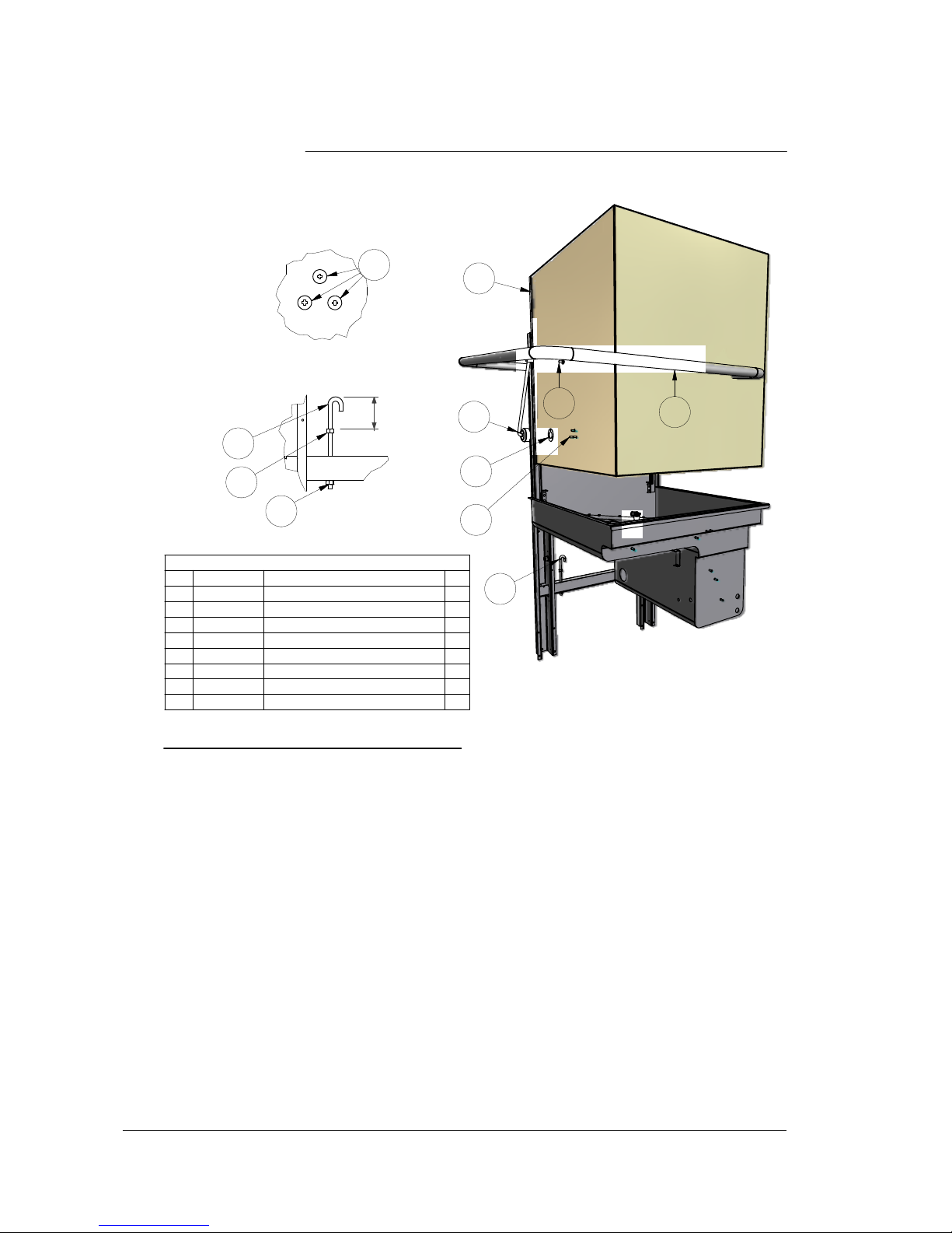
PERSPECTIVE VIEW
INSIDE DOOR
J BOLT ASSEMBLY
Parts List
QTYDESCRIPTION
PART NUMBERITEM
1M2 (3) PASS-THROUGH DOOR ASSY326 100071
3M5 x 12 SS TRUSS HEAD SCREW600 800172
1ASSY ME/M2 (3) DOOR HANDLE326 100373
1
PASSTHROUGH DOOR MOUNT GASKET
400 901204
1
M5 x 12 SS BUTTON HEAD CAP SCREW
600 800915
1M2(3) DOOR STAY ASSY326 100166
2M8 x170 J BOLT8899
7
2NUT HX ZP M881198
326 10010
4/03/2011
3-D
M2 (3) DOOR LINK & J BOLT ASSY
REV
See inside door
diagram above
2
NOTE: APPLY LOCTITE GRADE 243 TO
ALL FASTENERS BEFORE ASSEMBLY
6
0
1
6
4
2
5
7
8
3
INSTRUCTIONS FOR DOOR SPRING REPLACEMENT
Hazard Warning - service work to be carried out only by qualified persons. Ensure machine is isolated from Electrical Supply.
When replacing a broken door spring it is advisable that if possible the machine is disconnected from the services and moved out so work can be
carried out from the back of the machine.
Begin with the door in the down position and remove Item 5 M5 x 12 SS BUTTON HEAD CAPSCREW from the handle at both sides of the door.
Whilst holding the door handle down, remove item 6 M2(3) DOOR STAY ASSY from the door handle at both sides of the door and then allow the
door handle to rise to a vertical position.
NOTE:- IT IS IMPORTANT THAT THE DOOR HANDLE IS HELD DOWN WHEN CARRYING OUT THE ABOVE STEPS AS RELEASING IT TOO
SOON MAY CAUSE IT TO SWING UPWARDS IN AN UNCONTROLLED MANNER, CAUSING INJURY.
Move to the back of the machine and remove any parts of broken spring and check the J bolt and the spring hanger bracket for signs of wear. If the
spring hanger brkt is badly worn please refer to Technical Bulletin TB 9011 for the fitting of retrofit spring hanger brackets.
Hook the new spring in place on the J bolt and pull it up to hook onto the spring hanger brkt welded on the handle If this is not possible the lower nut
holding the J bolt in place should be unscrewed until the spring can be attached and then the lower nut should be tightened up to its original position
Once the new spring is fitted the handle can be lowered so that the door stays can be refitted and the capscrews fitted and tightened up. The
capscrews should have loctite or similar applied to them before fitting.
The door springs should be adjusted so that they hold the door against the door stops in the up position and the door does not lift by itself when in the
down position.
If the machine cannot be moved out, the front panel must be removed and the lower nut on the J bolt accessed from the front of the machine It will be
necessary to immobilise the J bolt using vice grips clamped onto it to prevent it turning when adjusting the lower nut. The upper nuts should not be
moved if at all possible.
8
7
Service Manual XP-2
30
Revision 1C
Page 31

PERSPECTIVE VIEW
326 10011
16/09/2013
3-D
M2 \ XP RACKSLIDE ASSY
REV
Parts List
QTYDESCRIPTION
PART NUMBERITEM
1M2(3) RACK SLIDE SUB ASSY MK2326 100121
2M5 x 25 SS HEX HD SETsCREW600 800943
2
NUT NYLOC M5 S/S
600 800604
2
NUT SS 304 HEX M8
600 80023
5
1AL RACK SLIDE GUIDE351 200606
2M8x20mm Hex-Head Bolt600 80030
7
5
7
3
3
6
7
5
4
4
1
Service Manual XP-2
31
Revision 1C
Page 32
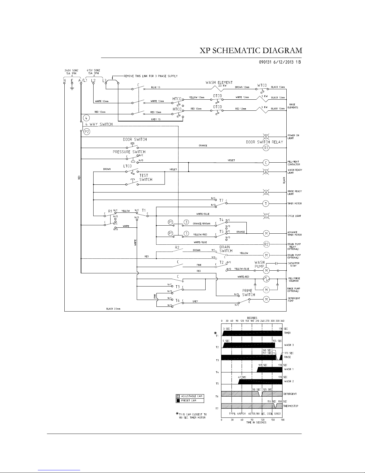
Service Manual XP-2
32
Revision 1C
Page 33
Service Manual XP-2
33
Revision 1C
Page 34

Spare Parts
DESCRIPTION PART NO
Cabinet & Door
Control Panel 208 20006
Control Panel Label 208 70001
Door Switch Magnet 600 30182
Spring Door 27 x 735 x 5 326 30019
Controls & Indicators
Contactor 600 30337
Auxiliary Contact 600 30339
Cord Set 15 600 30452
Door Reed Switch 600 30183
Door Switch Relay 600 30223
Knob Selector Switch 600 30467
Power Light 600 30161
Pressure Switch 600 30308
Ready Light 600 30162
Run Light 600 30163
Switch 4 position 600 30269
Terminal Strip 12 Way 3229
Test Switch 3035
Timer 32822
Temperature Gauge 600 90080
Heating Components
Over Temperature Thermostat 600 30088
Rinse Element 6 KW 3007
Rinse Tank Assembly 400 10169
Rinse Thermostat 3020
Wash Element 2.5 KW 600 30159
Wash Thermostat 30201
Hoses & Fittings
Lower Wash Connection Hose (75 mm long) 6196
Pressure Switch Hose (specify length) 3067
Rinse Hose (specify length) 600 60073
Rinse Tee SS 600 60230
Upper Wash Connection Hose (75 mm long) 6196
Upper Wash Manifold 326 30020
Wash Pump Inlet Hose (75 mm long) 6194
Wash Pump Outlet Hose (145 mm long) 6195
Service Manual XP-2
34
Revision 1C
Page 35

Spare Parts
DESCRIPTION PART NO
Pumps & Solenoids
Detergent Pump 1.5 L/H 600 30094
Dual Check Valve Assembly 400 10132
Rinse Aid Injector 600 30324
Solenoid Valve 3342
Wash Pump ZF 320V SX 600 30299
Wash Pump Capacitor 12.5 mF 3892
Wash Tank Components
Drain Upstand 400 10144
Pressure Bell 400 90135
Pressure Bell O Ring ARP 205
Rinse Nozzle Closed Head 600 40050
Rinse Nozzle Opened Head 600 40049
Rinse Nozzle O-Ring (OR R6 NBR) 600 40051
Scrap Tray 327 15001
Wash Nozzle Opened head 600 40015
Wash Nozzle O-Ring (OR 2050 NBR) 600 40048
Wash Pump Filter 326 20010
Wash / Rinse Arm Assembly 600 41148
Wash / Rinse Spindle 400 30223
Note:
For more parts look in the section “Assembly Diagrams”.
Service Manual XP-2
35
Revision 1C
Page 36
Service Manual XP-2
36
Revision 1C
Page 37
Service Manual XP-2
37
Revision 1C
Page 38
400 90144
19/11/2013
1-G
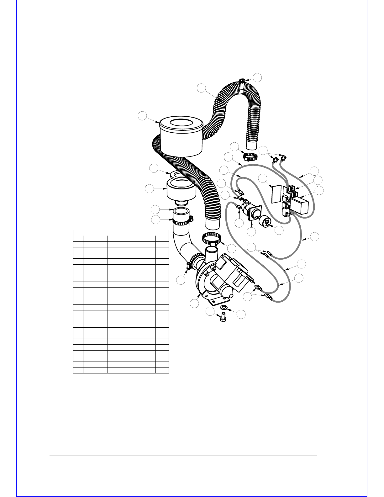
DRAIN PUMP KIT 0440031 - XP/AL3/AL8/PW1
REV
DRAIN PUMP KIT 0440031
QTYDESCRIPTIONPART NUMBERITEM
1
SWITCH C/RINSE ROLD SPCO
600 301021
4HOSE CLAMP ASS162
1
P CLIP
600 301733
1HOSE DRAIN 2.5M600 601054
1DRAIN PUMP600 601025
1MS HX SS 304 M6 x 12884616
1WASHER SPRING SS 304 M68566-1
7
1
UD UHB25 HOSE BEND
600 900748
1DRAIN PUMP UNION388239
1
GASKET DRAIN PUMP UNION
3882410
1RETROFIT DIAGRAM400 90014411
0.7mWIRE 0.75 YELLOW/BROWN600 3003212
1.5mWIRE 0.75 BLACK600 3001613
0.5mWIRE 0.75 RED600 3001514
0.2mWIRE 0.75 WHITE/BLUE600 3003315
0.2mWIRE 0.75 BROWN600 3002316
7
TERMINAL RED SPADE
H356017
2TERMINAL RED FLATH420718
1
BUTTON WITH DRAIN SYMBOL
600 3029719
1BASE 2 POLE RELAY600 3008120
1
RELAY 2 POLE (240VAC)
600 3008021
40mm3M VHB TAPEREF22
1ASSY DRAIN PUMP FILTER400 1002123
1. Pre-assemble the drain pump with the flexible outlet hose #4, the inlet hose #8, the drain pump union #9.
Secure the hoses with the supplied hose clamps #2.
2. Secure drain pump to base with M6 bolt #6 and the spring washer #7, provided in the kit.
3. Fit the drain union gasket #10 into the drain pump union #9. and screw the drain pump union #9 on to the drain waste of the
machine.
4. Secure drain outlet hose above the water level using P clip #3 supplied in the kit.
5. Cut out the right side hole below the wash temperature gauge in the control panel label (if see from the front). and fit the drain
switch #1. Fit the base and the relay #20 & 21 at the back of control panel using double-sided adhesive tape provided.
6. Wire the drain pump, the drain switch and the drain relay according to electrical diagrams, provided in service manual or
schematic diagram, supplied with the machine.
2
2
5
6
4
7
8
9
10
3
2
1
2
17
18
17
17
17
14
17
15
13
12
TO POWER
TERMINAL
TO SELECTOR
SWITCH
19
13
16
22
20
21
23
Service Manual XP-2
38
Revision 1C
Page 39

Revisions
Manual Revisions
REVISION REVISION FROM CHANGE
STATUS DATE SERIAL NO: DESCRIPTION
1A 10/08/13 133088
1B 19/11/13 add drain pump retrofit kit
1C 10/12/13 134202 add Auxiliary contact
Service Manual XP-2
39
Revision 1C
Page 40

Information supplied in this manual is copyright. No part of this work may be reproduced or copied in any
form or by any means, electronic or mechanical without the express permission of the author / publisher.
 Loading...