

Page 1

WARNING: ALL OPERATING AND MAINTENANCE PROCEDURES SHOWN ON THE NEXT
PAGE OF THIS MANUAL MUST BE FOLLOWED DAILY FOR PROPER OPERATION OF
YOUR WASCOMAT MACHINE.
PLEASE ENTER THE FOLLOWING INFORMATION AS IT APPEARS ON THE MACHINE(S)
DATA PLATE(S).
MAKE CERTAIN TO KEEP THIS MANUAL IN A SECURE PLACE FOR FUTURE
REFERENCE.
MACHINE TYPE OR MODEL
MACHINE SERIAL NUMBER(S)
ELECTRICAL CHARACTERISTICS:________ VOLTS, _______ PHASE,_______ HZ.
OPERATING & MAINTENANCE MANUAL
EX-30 S and EX-50 S
438 9030-13/01
99.20
Page 2

NOTICE TO: OWNERS, OPERATORS AND DEALERS OF WASCOMAT MACHINES
II
IMPROPER INSTALLATION AND INADEQUATE MAINTENANCE, POOR HOUSEKEEPING AND WILLFUL
NEGLECT OR BYPASSING OF SAFETY DEVICES MAY RESULT IN SERIOUS ACCIDENTS OR INJURY.
TO ASSURE THE SAFETY OF CUSTOMERS AND/OR OPERATORS OF YOUR MACHINE, THE FOLLOWING MAINTENANCE CHECKS MUST BE PERFORMED ON A DAILY BASIS.
1. Prior to operation of the machine, check to make certain that all operating instructions and
warning signs are affixed to the machine and legible. (See the following page of this manual
for description and location of the signs.) Missing or illegible ones must be replaced immediately. Be sure you have spare signs and labels available at all times. These can be obtained from your dealer or Wascomat.
2. Check the door safety interlock, as follows:
(a) OPEN THE DOOR of the machine and attempt to start in the normal manner:
For coin-operated models, select a wash cycle, insert the proper coins and press the
START button.
For manually operated models, select a wash cycle and press the START button.
THE MACHINE(S) SHOULD NOT START !
(b) CLOSE THE DOOR to start machine operation and, while it is operating, attempt to
open the door without exerting extreme force on the door handle. The door should
remain locked!
If the machine can start with the door open, or can continue to operate with the door
unlocked, the door interlock is no longer operating properly. The machine must be
placed out of order and the interlock immediately repaired or replaced.(See the door
interlock section of the manual.)
3. DO NOT UNDER ANY CIRCUMSTANCES ATTEMPT TO BYPASS OR REWIRE ANY OF
THE MACHINE SAFETY DEVICES AS THIS CAN RESULT IN SERIOUS ACCIDENTS.
4. Be sure to keep the machine(s) in proper working order: Follow all maintenance and
safety procedures. Further information regarding machine safety, service and parts can be
obtained from your dealer or from Wascomat through its Teletech Service Telephone - 516/
371-0700.
All requests for assistance must include the model, serial number and electrical characteristics as
they appear on the machine identification plate. Insert this information in the space provided on the
previous page of this manual.
5. WARNING: DO NOT OPERATE MACHINE(S) WITH SAFETY DEVICES BYPASSED, REWIRED OR
INOPERATIVE! DO NOT OPEN MACHINE DOOR UNTIL DRUM HAS STOPPED ROTATING!
Page 3

CAUTION
1. Do not open washer door until cycle is completed, operating
light is off, and wash cylinder has stopped rotating.
2. Do not tamper with the door safety switch or door lock.
3. Do not attempt to open door or place hands into washer to
remove or add clothes during operation. This can cause
serious injury.
MACHINE SHOULD NOT BE USED BY CHILDREN
PRECAUCION
1. No abra la puerta de la máquina lavadora sino hasta que la
máquina haya terminado su ciclo, la luz operativa esté apaga
da y el cilindro de lavado haya completamento terminado de
girar.
2. No interferia o manipule el switch o la cerradura de la puerta.
3. No trate de abrir la puerta o meta las manos dentro de la
máquina para meter o sacar ropa mientras la máquina está
en operación, pues puede resultar seriamento herido.
LAS MÁQUINAS NO DEBEN SER USADAS POR NIÑOS
SAFETY AND WARNINGS SIGNS
Replace If Missing Or Illegible
One or more of these signs must be affixed on each machine as indicated, when not included as part of the front instruction panel.
LOCATED ON THE OPERATING INSTRUCTION SIGN OF THE MACHINE:
Page 4

Page 5

5
Contents
Introduction .................................................................................... 7
Technical data................................................................................ 8
Installation .................................................................................... 11
Safety rules ..................................................................................21
Operating instructions ..................................................................22
Programming................................................................................27
Wash programs............................................................................ 30
Mechanical and electrical design .................................................33
Serviceprogram............................................................................ 70
Trouble shooting .......................................................................... 73
Safety instructions
• This machine is designed for water washing only.
• This machine must not be used by children.
• All installation operations are to be carried out by qualified
personnel. Licensed personnel are necessary for all electric
power wiring.
• The interlock of the door must be checked daily for proper
operation and must not be bypased.
• All seepage in the system, due to faulty gaskets etc., must be
repaired immediately.
• All service personnel must be fully familiar with the operating
manual before attempting any repair or maintenance of the
machine.
• This machine must not be sprayed with water, otherwise short
circuiting may occur.
• Fabric softeners with volatile or inflammable fluids are not to
be used in the machine.
The manufacturer reservs the right to make changes to design and
material specifications.
EX-30 S, EX-50 S
Page 6

Page 7
7
4688
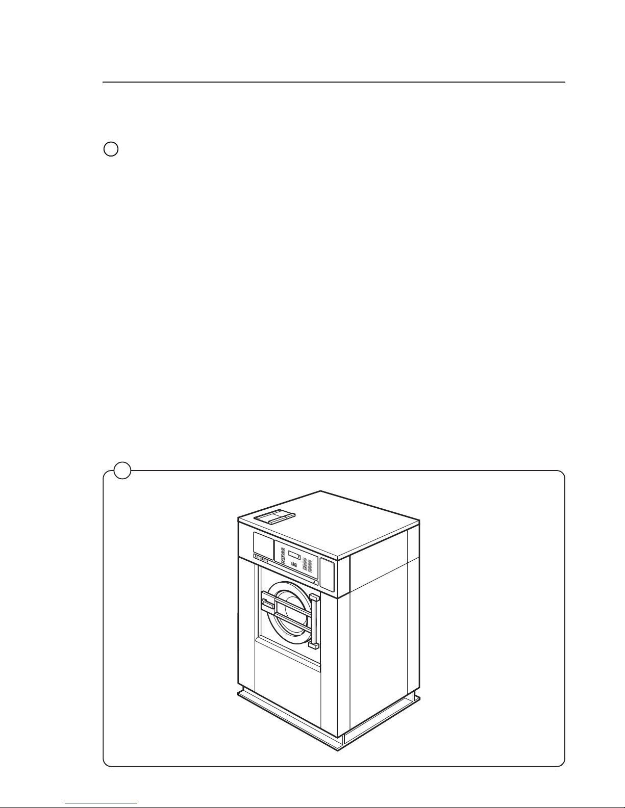
Introduction
1
Introduction
The Selecta models washer/extractor has been developed to cover the heavy
duty requirements of hotels, motels, nursing homes, hospitals, professional
laundries, restaurants, airlines, steamships, schools, colleges and all on-premises laundries where flexibility and quick formula variation, coupled with high
quality automatic washing, are required.
The machines are free-swinging, i.e., the drum is moveable and spring suspended in relation to the frame. This minimizes vibrations transferred to the frame
thus simplifying installation, as no concrete base is required.
The high speed spin gives a G factor of approximately 300, providing very
efficient water removal during the spin.
All parts of the machine which come into contact with the items being washed
are made of heavy gauge surgical stainless steel, ensuring long life and lasting
beauty, as well as full protection for no-iron fabrics. All electrical components
are made accessible for servicing by simply removing the top panel.
This manual contains a technical description of the machine and instructions for
its installation, operation and maintenance. Together with the wiring diagram
which accompanies each individual machine it should be kept in a safe place
for easy reference.
When ordering spare parts or contacting Wascomat for any purpose always
give the machine serial number, model, voltage and other electrical characteristics appearing on the nameplate at the rear of the machine.
Fig.
1
60
40
60
95
60
40
30
Page 8

8
Technical data
EX 30 S
Dry load capacity up to 30 lbs
Overall dimensions Width 870 mm 34 1/4'’
Depth 790 mm
Height 1325 mm
Net weight 290 kg 639 lbs
Floor load 3.3 ± 1.1 kN 790 ± 264 lbs force
Crated dimensions Volume 1.25 m
3
44 cu.ft
Weight 315 kg 695 lbs
Inner drum Diameter 620 mm 24 7/16'’
Depth 412 mm 16 5/16'’
Volume 120 litre 4.4 cu.ft
Speed of rotation Wash 24-48 r.p.m.
Distribution 78 r.p.m
Extraction up to 950 r.p.m.
G-factor During wash 0.8
During high extract 120-310
Voltage requirements 208-240 V 1-Phase 60 Hz
Rated power
Motor system 598 W
Extraction 1900 W
Overcurrent protection 1-Phase 15 A
Water connections
Water pressure, max 10 kp/cm
2
142 psi
Recommended water pressure 2-6 kp/cm
2
25-85 psi
Hose connection, water 20 mm 3/4'’
Hose connection, drain 75 mm 3'’
Page 9

9
Technical data
EX 50 S
Dry load capacity up to 50 lbs
Overall dimensions Width 1000 mm 39 3/8'’
Depth 900 mm
Height 1435 mm
Net weight 553 kg 1218 lbs
Floor load 6.0 ± 2.0 kN 1440 ± 480 lbs force
Crated Dimensions Volume 2.05 m
3
72.3 cu.ft
Weight 588 kg 1295 lbs
Inner drum Diameter 750 mm 29 1/2'’
Depth 500 mm 19 11/16'’
Volume 220 litre 7.8 cu.ft
Speed of rotation Wash 44 r.p.m.
Distribution 70 r.p.m.
Extraction up to 850 r.p.m.
G-factor During wash 0.8
During High Extract 120-300
Voltage requirements Motor system 208-240 V 1-Phase 60 Hz
Rated power Wash 756 W
Motor, extraction 3000 W
Overcurrent protection 1-Phase 20 A
Water connections
Water pressure, max 10 kp/cm
2
142 psi
Recommended water pressure 2-6 kp/cm
2
25-85 psi
Hose connection, water 20 mm 3/4'’
Hose connection, drain 75 mm 3'’
Page 10

10
Technical data
mm mm
A 870 1000
B 1325 1435
C 915 1100
D 790 900
E 125 200
F 630 615
G 570 550
H 470 600
J 1075 1170
K 200 230
L 170 170
M 110 110
N 1215 1325
O – 200
P 140 140
Q 1140 1235
R 175 175
S 305 370
T 1110 1220
U60 60
Outline and dimensions
4699
1. Opening for electrical cable connection
2. Steam connection (optional)
3. Cold water
4. Hot water
5. Hot water (only EX 50)
6. Drain outlet
7. Soap box
8. Liquid supply connections
EX 50 S
EX 30 S
6
5
G
F
B
E
C
D
T
U
4
1
2
S
R
J
Q
N
7
3
H
K
O
L
P
M
A
Page 11
11
Installation
2
3
4
1247 B
1248 B
1249 B
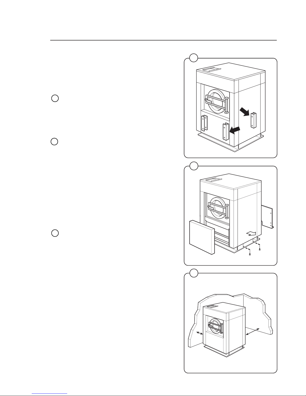
Installation
The machine is delivered with expansion bolts
and other items packed inside the drum.
Shipping securities
The machine is shipped with four large metal
brackets bolted to the four suspension legs as
well as a support between the pulley and the
back plate.
Prior to installation, follow these steps:
• Unpack the machine.
• Remove the lower front panel and the two rear
panels.
• Remove the support from the pulley at the
back of the machine.
• Remove both front brackets.
• Remove both rear brackets.
Placement
The machine should be installed close to a floor
drain or open drain to make installation, use and
service easier.
The following clearances are recommended for
ease of installation and service:
• At least 20 inches between the machine and
the wall behind it.
• At least 2 inches on each side.
The floor must be able to support a static load of
790 lbs for the EX-30 and 1440 lbs for the EX-50.
The maximum impact load at extraction is 260
lbs force for the EX-30 and 480 lbs for the EX-50.
Fig.
2
Fig.
3
Fig.
4
300 mm
1000 mm
Page 12
12
Installation
5
6
7
0620
0621
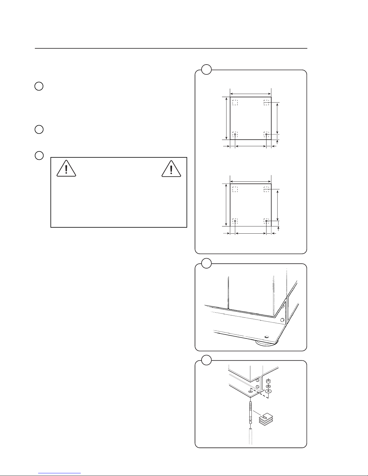
Mechanical installation
• Mark and drill two holes 3/8'' in (8 mm) in
diameter and approximately 3 1/2'' in. (90 mm)
deep according to the dimensions in figure 5.
• Place the machine in position. Never lift the
machine by the door or handle.
• Check that the machine is level and steady.
Use stainless or galvanized washers between
the machine and the floor.
• Insert the expansion bolts supplied with the
machine. Fit the washers and nuts.
It is of utmost importance that the machine
is level, from side-to-side as well as frontto-rear. If the machine is not properly
levelled, it may result in out-of-balance
cutout without a real out-of-balance in the
drum.
Fig.
5
Fig.
7
Fig.
6
4811
870
780
33
4343
790
716
=
=
Front
Front
=
=
1000
910
33
4343
900
830
EX 30 S
EX 50 S
Page 13
13
Installation
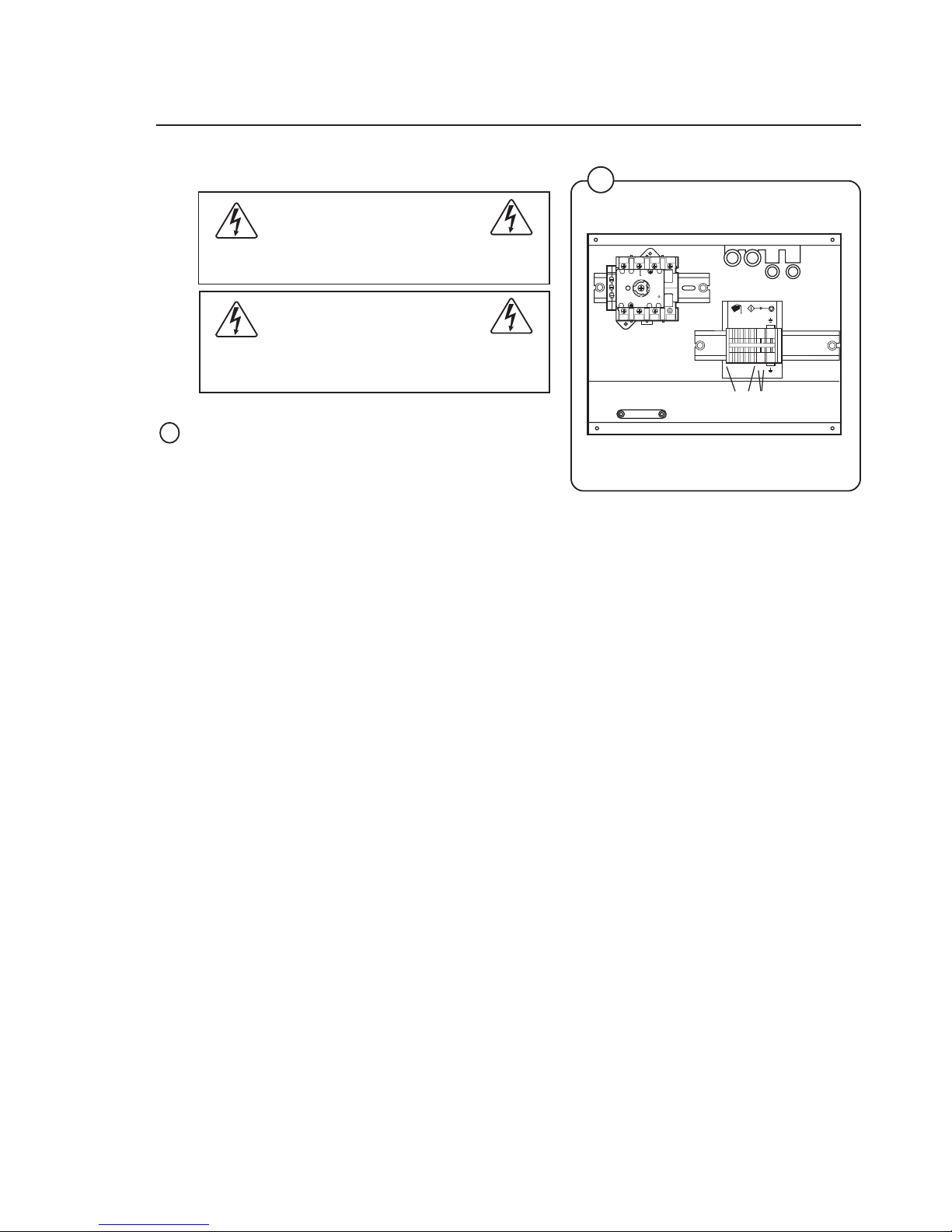
Connection for liquid supply (option)
Electrical installation must be carried out
by an authorized personnel!
Installed appliances must be EMC approved
according to EN 50081-1 and EN 50082-2.
The connections A (1-5) are signals for the liquid
supply pumps.
The connections B are for Neutral (1) and Phase
(2).
8
4722
Fig.
8
T1
T2
T3L1N
N
L2
L3
X146-1
471 75 98 01
12
3
4
125
12
3
4
125
A B
Page 14
14
Installation
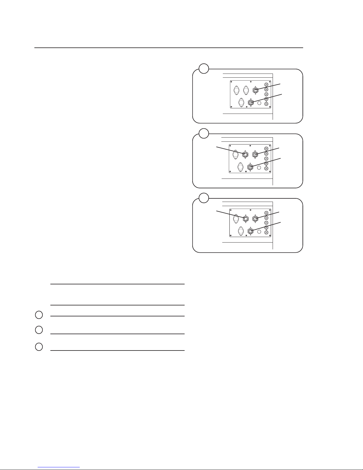
Water connections
All intake connections to the machine are to be
fitted with manual shut-off valves and filters, to
facilitate installation and servicing. In certain
cases non-return valves will need to be fitted
before the machine to comply with local plumbing
regulations.
Water pipes and hoses should be flushed clean
before installation. After installation hoses should
hang in gentle arcs.
The machine may have between two and four
DN 20 (R 3/4") water connectors. All connectors
present on the machine must be connected up.
The table shows the possible connection options,
which will depend on the water types to be
connected to the machine. Check the machine
plates too.
All water connectors must be connected up,
otherwise the wash program will not function
correctly.
Hoses are to be of an approved type and grade,
to comply with national regulations.
The water pressure data is as follows:
• min: 40 kPa (0,4 kp/cm
2
)
• max: 1 MPa (10 kp/cm
2
)
• recommended: 200-600 kPa (2-6 kp/cm
2
)
Water type Water connection
12 3 4
cold and hot cold hot
cold, hot and
cold/hard cold hot cold/hard
cold and hot cold hot cold or
hot
Fig.
9
Fig.
10
Fig.
11
9
10
11
4702
4703
4705
Hot
Cold
EX 30 S
Cold
EX 30 S
Hot
Cold
EX 50 S
Hot
Cold
Hot/
Cold
Page 15

15
Installation
Drain connection
Connect a 3'’ (75 mm) flexible hose to the drain
outlet of the machine.
The drain must not have any sharp bends and
must slope downward from the machine to
assure proper drainage. The outlet must open
freely to the main drain.
Do not reduce the size of the drain connection
from the machine to the waste line.
12
1258
Fig.
12
Page 16
16
Installation
13
1719
STEAM HOSE APPROVED FOR
min. 0,1 MPa
max. 0,8 MPa
CABLE FROM MACHINE
SEAL WITH TEFLON
OR SIMILAR
CONNECTION STEAM
INJECTOR IN MACHINE
For rebuilding look at the wiring diagram of the machine.
Page 17
17
Installation
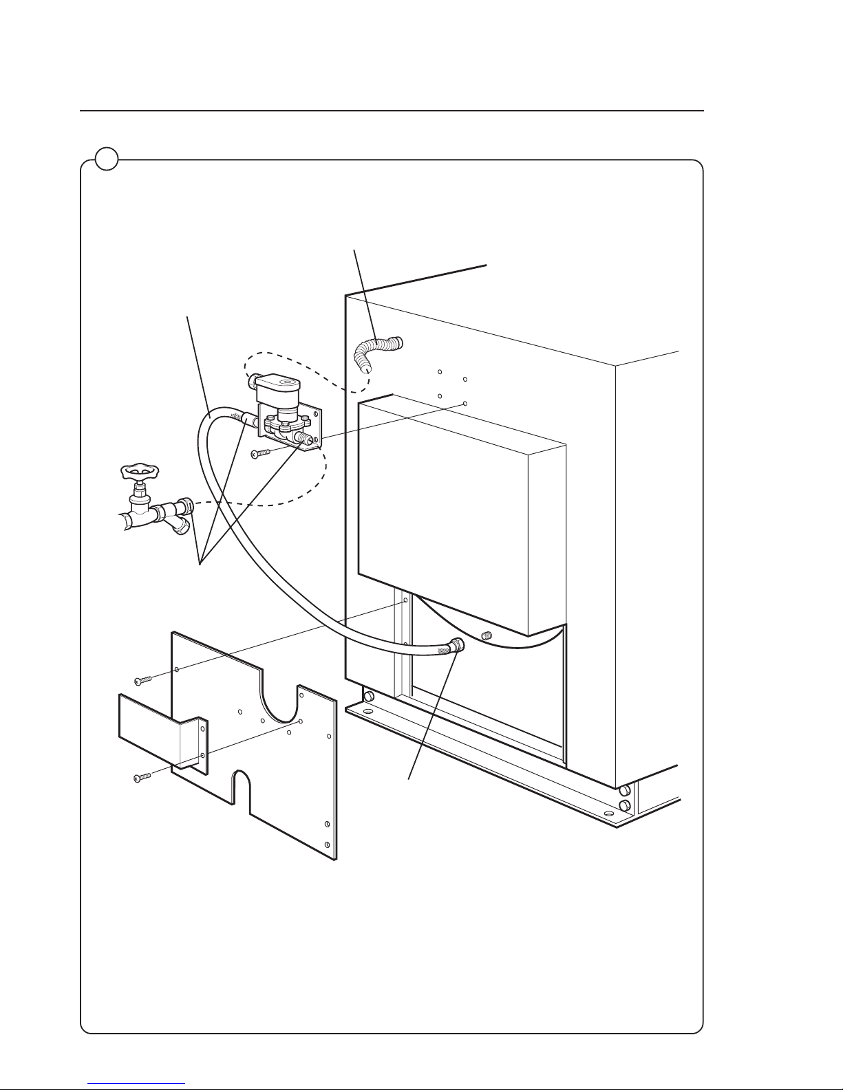
Steam connections (optional steam heating)
Steam pressure required:
• minimum 7 PSI
• maximum: 110 PSI
• recommended: 40-85 PSI
A steam valve for this machine type is fitted
separately in a bracket on the upper rear cover
plate. The steam valve, hose and filter are supplied with the machine.
Steam-flush all pipes and hoses before connection.
Installation instructions:
• Install rear cover plates.
• Install steam valve bracket and valve. The
steam valve must be mounted in upright
position.
• Connect the steam hose between the steam
valve and the steam intake on the machine.
• The steam inlet pipe must be fitted with a
manual cut-off valve. Fit the filter supplied with
the machine to the manual cut-off valve.
• Connect an approved 1/2'' steam hose between the steam valve and the filter. The
connection must be vertical or be fitted with a
pipe connector in order to avoid sharp angles
in the hose.
• Connection size at filter: DN15 (R 1/2''').
Check that there are no sharp angles or
bends in the connection hose.
14
1254
Fig.
14
Page 18
18
Installation
15
Fig.
15
4724 B
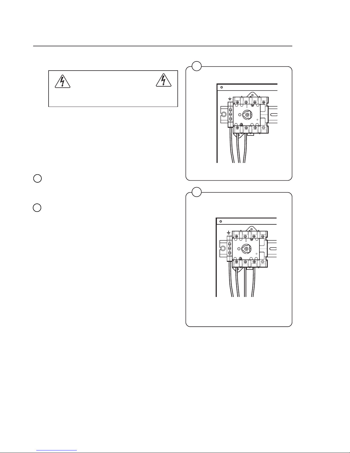
Electrical installation
Electrical installation must be carried out
by an authorized personnel!
Mount a multi-pole switch prior to the machine to
facilitate installation and service operations.
The connecting cable should hang in a gentle
curve.
Fuse size can be found on next page.
Single-phase connection:
Connect the earth and other two wires as shown
in example "1AC" in the figure.
Three-phase connection:
Connect the earth, neutral and phase wires as
shown in example "3AC" in the figure.
When the installation is completed, check:
• that the drum is empty,
• that the machine operates by turning on the
mains switch, starting the machine and using
RAPID ADVANCE to reach the spin cycle
(see operations manual).
16
4726
Fig.
16
T1
T2
T3L1N
N
L2
L3
T1
T2
T3L1N
N
L2
L3
1AC
3AC
Page 19

19
Installation
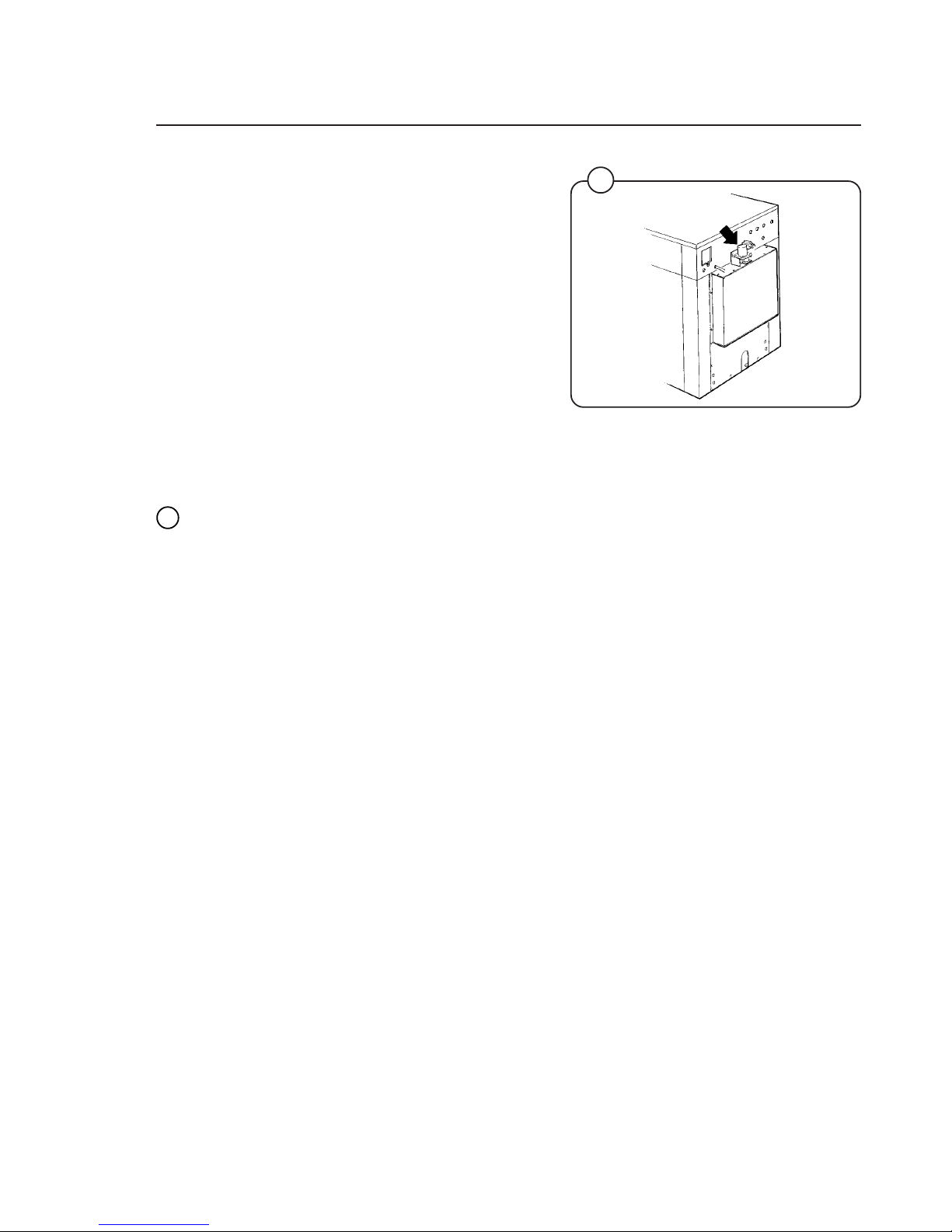
Setting the timing on the electrolube oil dispenser
This machine is equipped with an electronic oiler
which lubricate the seals on a timed bases. With
the rear panel removed locate the oiler, which is
attached to the base frame at the lower rear.
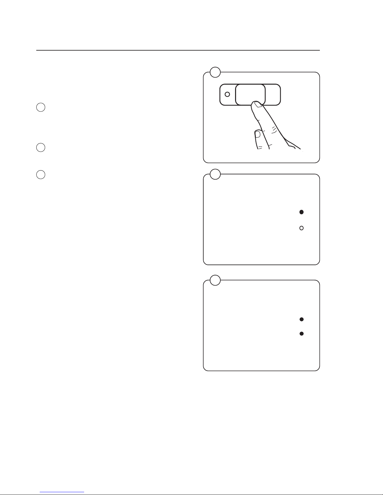
Pry off the switch panel cap with a screwdriver.
• Under the cap are the switches for time setting.
• The light will start flashing after a few minutes
and will continue to flash every 15th to 20th
seconds as long as the dispencer is in operation.
• The decal shown below should be affixed at
the front of the machine and updated as
required.
Fig.
19
2207
19
18
17
2208 A
Date Last Replaced Date Last Replaced
IMPORTANT
NOTICE
This machine is equipped with an automatic oiler,
located at the right rear of the machine, which keeps
it lubricated for long bearing and seal life.
The amount of oil in the container is sufficient for
approximately one year's lubrication. It is of utmost
importance that the oiler does not become empty.
Therefore we recommend that the rear panel be
removed and a visual inspection made on a
bimonthly basis. When the oil reaches a low level,
the cannister must be replaced with a new one
available from Wascomat as Part No. 827601.
Fig.
17
Fig.
18
Page 20

20
4944
Start-up and safety checklist
Before initial start-up of an EX 30 S/EX 50 S
washer, the following safety checks must be
performed:
• Make sure that all electrical and plumbing
connections have been made in accordance
with applicable local codes.
• Use only flexible water fill and drain hoses of
the proper length to avoid sags and kinks.
• Make sure the machine is properly grounded
(electrically).
Before the machine is operated, the door safety
interlock must be checked for proper operation
as follows:
• When washer loading door is open, the
machine must not start. Verify this by attempting to start washer with door open.
• When washer is in operation, the loading door
is locked and cannot be opened. Verify this by
attempting to open the loading door when the
machine is operating. If necessary, consult
this manual for proper operation of the door
safety interlock or call a qualified serviceman.
If the machine starts with the door open or
the door can be opened after machine is
running, the machine must immediately be
placed OUT OF ORDER and the door
interlock system must be repaired or
replaced. Disconnect electrical power from
the machine until the necessay repairs are
made.
Door safety interlock must be checked
daily in accordance with above procedure.
Before servicing Wascomat equipment,
disconnect electrical power.
Fig.
20
Fig.
21
20
Installation
21
4945
123
45
6
7
89
0
123
45
6
7
89
0
Page 21

21
• This machine is designed for water washing only.
• Machines must not be used by children.
• All installation operations are to be carried out by qualified personnel.
Licensed personnel are necessary for all electric power wiring.
• The interlock of the door must be checked daily for proper operation
and must not be bypassed.
• All seepage in the system, due to faulty gaskets etc., must be repaired
immediately.
• All service personnel must be fully familiar with the operating manual
before attempting any repair or maintenance of the machine.
• This machine must not be sprayed with water, otherwise short
circuiting may occur.
• Fabric softeners with volatile or inflammable fluids are not to be used in
this machine.
Safety rules
Safety rules
Page 22

22
1
Supply
signals
A
B
2
3
4
5
START
STOP
6
1
Program
step
7
Final extract
Doorlock delay
Door unlocked
2
3
4
5
Prewash
Mainwash
Rinse
Operating instructions
Operating instructions
The Emerald Series program unit controls the various functions of the machine
in a certain time sequence with the aid of seven built-in standard programs.
The standard programs can also be modified by selecting various options. By
selecting options, the user has access to programs for all types of wash loads
and degrees of soiling.
The control panel consists of program selection buttons (A) and (B), a
combined start, pause and rapid advance button (C), symbols with LEDs (D)
which show the program selected and the program sequence, plus an alphanumeric display (E).
The alphanumeric display shows illuminated green characters.
In the event of faults, error codes will be displayed on this window. See Fault
codes.
22
Explanation of control panel
A Program selection buttons
B Option buttons
C Start/pause and rapid advance button
D Symbols with LEDs to indicate program sequence
E Information display
4996
Fig.
22
D
E
B
A
C
Page 23

23
Operating instructions
Washing
• Press the button for the desired program.
• Now the LEDs alongside the program symbols will show what the selected program
consists of.
• Press the button(s) for any options required.
Gentle actions consists of 6 seconds
rotation, as opposed to 18 seconds pause
and 6 seconds pause and 14 seconds
rotation for Normal action.
• Press the START button.
3426
4995
3435
24
Fig.
23
Fig.
24
Fig.
26
27
Fig.
25
Perm Press
Quick-Wash
2
3
4
5
START
Hot
Warm
Cold
Delicate
Heavy Soil
6
1
7
START
Fig.
27
A
B
25
26
23
1
Supply
signals
Program
step
Final extract
Doorlock delay
Door unlocked
2
3
4
5
Prewash
Mainwash
Rinse
Page 24

24
• Now the display will show the clock symbol
and two digits. The two digits are the time left
before the wash will be finished.
The two digits indicating time left will not
appear when the machine is first installed.
Each program needs to have been used at
least once before the time left will be displayed.
• For 5 minutes immediately after START is
pressed the colon character (
: ) will flash on
the display. As long as this character is still
flashing a new program can be selected
(without the drain opening). This means you
still have the chance to change the setting if
the wrong program has been selected. Do as
follows:
• Press START.
• Select a new program.
• Press START again after making any change
in the program selected.
If for any reason you wish to halt the wash cycle
for a time, press the START button for a moment
or two. The program will be suspended and the
drain will remain closed.
To restart the program, press the START button
again briefly.
Fig.
28
Operating Instructions
Fig.
29
Fig.
30
30
3435
START
4091
29
3141
28
1
Page 25

25
START
Operating Instructions
For coin-operated machines
Select a wash program, then insert the number
of coins corresponding to the figure shown on
the display.
As each coin is added the machine counts
backwards towards 00 on the display. The
machine will not start until the display shows 00.
• Press the START button.
• Now the display will show the clock symbol
and two digits. The two digits are the time left
before the wash will be finished.
The two digits indicating time left will not
appear when the machine is first installed.
Each program needs to have been used at
least once before the time left will be displayed.
• For a time immediately after START is pressed the colon character (
: ) will flash on the
display. As long as this character is still
flashing a new program can be selected
(without losing anything). This means you still
have the chance to change the setting if the
wrong program has been selected.
• Press PAUSE/START.
• Select a new program.
• If the new program costs more to run than
the amount already paid, the difference will
be shown on the display. Insert enough coins
to make the display show 00 again.
• Press START again after making any change
in the program selected.
3435
2253
Fig.
31
3141
31
32
33
Fig.
32
Fig.
33
Page 26
26
Doorlock delay
Door unlocked
Rapid advance
Whole steps in programs can be skipped using
rapid advance.
• Press and hold the START button until the
program indicator LEDs have moved past the
program steps you wish to skip.
Program end
After final extraction, the LED by the "doorlock
delay" comes on. This shows that the door lock
will shortly be unlocked.
The door will not actually be unlocked until the
green LED by the "door unlocked" comes on,
accompanied by an audible signal. This takes
about 1 minute.
Troubleshooting
If the machine won’t start, check that:
• the circuit breaker is on.
• the manual shut-off valves for water are open.
• a program has been selected.
• the door is properly locked.
3435
Fig.
34
3424
3425
Fig.
36
Operating Instructions
34
35
36
Fig.
35
START
Doorlock delay
Door unlocked
Page 27

27
A
1
1
4
3
2
6
5
8
7
9
Programming
Coin-operated machines
In coin-operated machines the prices for the
various programs have to be programmed in.
Values from the coin mechanism (the
accumulated value) can be read out with the aid
of the service program.
If a machine is fitted with a coin mechanism after
its original installation the relevant electronic
circuitry will have to be activated before the prices
can be programmed in.
Only trained service personnel may use the
service program and program in prices for
coin operation.
Activation of electronic circuitry in machines fitted with coin operation after original
installation.
• Press the service button.
Now certain of the buttons switch to being
number keys (1 to 9), with the START button
being 0.
3429
Fig.
37
Fig.
38
38
3400
37
Page 28

28
Programming
Codes 91 and 92 are used to store the values for
coin slots 1 and 2. For mechanisms with only one
slot, only code 91 is used.
The values to be stored are the ratio of one coin
to the other.
For example: if the coin slots are for a 10 cent
coin and a 50 cent coin. The value 10 should be
stored under code 91, and the value 50 should
be stored under code 92.
• Enter code 91 using the buttons which have
become number keys 9 and 1.
The display will now show 91.
• When entering the actual value: keep the
price-programming button activated (the
switch is located under the top cover at the
right front edge). Enter the value 1 and then
release the button.
• Enter code 92. The display will now show 92.
• Enter the value 5.
• Exit the service program by pressing the
service button again.
2275
2274
2276
2272
3400
39
40
41
4243
Fig.
39
Fig.
40
Fig.
41
Fig.
42
Fig.
43
Page 29

29
Programming
Price programming:
• Press the relevant wash program selector
button.
When programming the price of a wash program
plus options, press both the relevant program
selector button and the option button.
• Keep the price-programming button activated.
Now the display shows 00 plus the coin sym-
bol.
• Enter the price via the numerical key functions.
The START button can be used to enter 0.
• Release the price-programming button.
This procedure should be repeated for all wash
programs.
2273
44
Fig.
44
Page 30

30
Hospitality wash formulas
For hotels/motels, restaurants, retirement communities, schools and
universities, commercial and institutional laundries.
Wash programs
1 White uniforms
sheets & pillowcases (light
soil)
2 White uniforms
sheets & pillowcases (light/
medium soil)
3 White uniforms,
sheets, pillowcases (medium
soil)
4 Colored uni-
forms, sheets,
pillowcases
(light soil)
5 Color uniforms,
sheets, pillowcases (medium
soil)
6 White towels
(light soil)
7 White towels
(medium soil)
1A White towels
(medium soil
short program)
2A Colored towels
3A White towels
(heavy soil)
4A Bedspreads/
delicates
(cold water)
5A Kitchen &
housekeeping
rags
6A Mops
7A Stain treat-
ment (short
formula)
1B White table
linen (bleach,
no starch)
2B Colored table
linen (bleach,
no starch)
3B White or colored
table linen
(no bleach,
no starch)
4B White 100%
polyester (VISA)
table linen
5B Colored
100% polyester
(VISA)
table linen
6B Chef coats
7B Stain treat-
ment (long
formula)
1AB White table
linen (bleach
and starch)
2AB Colored table
linen (bleach
and starch)
3AB White or
colored table
linen (starch,
no bleach)
4AB Bedspreads/
delicates
(warm water)
5AB Light soil
general wash
formula
6AB Extra rinsing
with extract
7AB Test program
Page 31

31
Healthcare wash formulas
For nursing homes, hospitales and medical center.
Wash programs
1 White uniforms
sheets & pillowcases (very
light soil)
2 White uniforms
sheets & pillowcases (medium/
heavy soil)
3 White uniforms,
sheets, pillowcases (medium/
heavy soil)
4 White uniforms
sheets, pillowcases
(heavy soil)
5 Color uniforms
sheets, pillowcases
(medium soil)
6 White towels
(light/medium
soil)
7 White towels
(heavy soil)
1A Diapers/pads
medium soil
2A Diapers/pads
heavy soil
3A Diapers/pads
extra heavy
soil
4A 100% polyester
pads
5A Delicates/
bedspreads
6A Sheepskins/
cubicle
curtains
7A Personals/
general ldry.
1B Colored uni-
forms, sheets
& pillowcases
(light soil)
2B Colored towels
3B Dietary and
kitchen rags
4B Housekeeping
rags
5B Mops
6B Stain treatment
(short formula)
7B Stain treatment
(long formula)
1AB White cotton
or blend
table linen
2AB Colored
cotton or
blend
table linen
3AB 100%
polyester
(VISA)
table linen
4AB AIDS/
infectious
disease isolation in
water
soluble bags
5AB Rinse and
extract
(cotton/terry)
6AB Rinse and
extract
(polyester)
7AB Test program
Page 32

32
Shirt laundry formulas
Wash programs
1 Shirts
(starch, cold
rinses)
2 Shirts
(starch, warm
rinses)
3 Shirts
(no starch)
(may use with
formula 5 or 6)
4 Shirts
(no starch, no
bleach) (may
use with
formula 5 or 6)
5 One starch
injection
with extract
6 Two starch
injections
with extract
7 Short rinse
and extract
1A Short formula
shirts
(no starch)
(may use with
5 or 6)
2A Heavy soil
shirts (one
starch
injection)
3A Shirts
(pause for
starch)
4A Light soil
general wash
no-iron fabrics
5A Light soil
general wash
(cotton)
6A Shirts
(no starch,
short extract)
(may use with
formula 5 or 6)
7A Shirts
(starch, short
extract)
1B Delicates
2B Mops
3B Extra heavy
soil – no –
iron fabrics
4B Extra heavy
soil – cotton
fabrics
5B Wool blankets
6B Stain treat-
ment
7B Stain soak
(supplies added
manually)
1AB White or colored
blend
table linen
(with bleach,
no starch)
2AB White or colored
blend
table linen
(with bleach
and starch)
3AB White or colored
100% polyester
(VISA)
table linen
(white bleach,
no starch)
4AB White or colored
100% polyester
(VISA) table
linen (with
bleach and
starch)
5AB White cotton
blankets
6AB Uniforms
7AB Test program
Page 33

33
Mechanical and electrical design
Maintenance
This machine has been carefully designed to minimize preventive
maintenance. However, the following routine operations should be
performed at regular intervals (depending on how much the machine is
used).
Daily
• Clean detergent residue from the door seal and check that the door
does not leak.
• Clean the detergent compartments and wipe down the machine with a
damp cloth.
• Check that the drain valve does not leak.
• Start the machine and check that the door is locked while the machine
is operating.
Every three months
• Check for leaks in valves, hoses and connections.
• Remove any lint from the machine’s drainage system.
• Check water inlet screens for clogging.
Page 34

34
45
Inlet valves,
water
Automatic
control unit
Motor control unit
4679
Detergent
dispenser
Control
panel
Machine
door
Drain valve
Frame
Damper
Motor
Outer drum
PCU
board
Heating relay
Transformer
60
40
60
95
60
40
30
Elements
Machines with permanent programs
Steam valve
(obscured)
Oil lubrication
Imbalance
switch
Door lock
Inward power
supply
terminals
Spring
suspension
Mechanical and electrical design
Page 35

35
Mechanical and electrical design
The washing machines are controlled by a microprocessor program unit.
This provides several major advantages:
• The control of times, levels and temperatures takes place with
considerable precision and flexibility
• The large character display provides detailed information in clear text
about the different wash programs, the machine's different activities,
relevant wash times and temperatures.
• The user is able to program new wash programs and adapt the
programs exactly on the basis of previous experience, different kinds of
materials, the degree of soiling etc. Depending on the length of the
program, up to 90 different programs can be programmed. Refer to the
separate appendix for programming.
• When supplied, the machine is provided with a number of standard
programs.
• Machine safety can be maintained at a very high level through
continuous monitoring and integral safety checks.
• The machine has an integral service program for testing machine
functions.
To avoid high mechanical stresses during the spin cycle, the machine is
fitted with an automatic imbalance sensor. The spin cycle is discontinued if
imbalance occurs, the machine is filled with water and the machine operates with a reversing action to redistribute the wash goods. The drain valve
then opens, the machine operates at distribution speed and a new spin
cycle starts.
The machine can also be operated manually.
The electronic controls together with carefully considered machine design
based on long experience also provide:
• simple installation and a long service life.
• a low noise level.
• maximum water removed as a result of the high speed spin cycle and
the large drum diameter.
• low water and power consumption in relation to capacity.
• extreme ease of servicing.
The C-machines are equipped with a frequency control and a multi-speed
motor. This gives advantages such as:
• very smooth drum rotation through a slow acceleration of the drum.
• wash with reduced speed.
• quiet operation.
• improved distribution of the load.
Page 36

36
Mechanical and electrical design
4709
Frame
Description
The frame is constructed on the free-swinging principle, i.e. the washing
drum is freely and resiliently suspended in the fixed frame.
The entire frame is constructed of U-shaped iron beams forming a stable
and torsionally rigid structure.
The suspension device for the drum unit and motors consists of four posts,
one in each corner, each with a robust spring to which the washing drum
supports are attached. In order to prevent excessively great vibrations
which can be caused by imbalance in the drum, a shock absorber is fitted
between the drum and frame by each spring. (The EX 30 model has twin
shock absorbers at the front.)
Repair instructions
If the out-of-balance cutout is repeatedly triggered
• Check the shock absorbers, replace them if required. Note that the
shock absorbers should be fitted with the plunger rod upwards.
• Check the attachment of the springs:
- the spring is attached by a bolt from above: Check that it has been
properly tightened down.
The entire spring unit should be replaced in spring replacement.
Fig.
46
46
Page 37
37
0635
Mechanical and electrical design
47
Drum with bearings
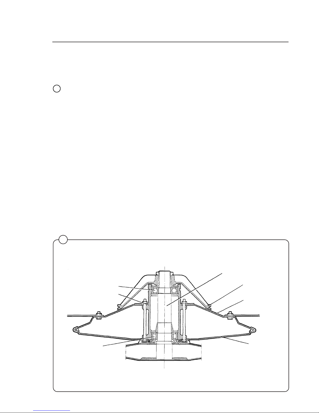
Description
The inner drum is journalled to the outer drum by two robust bearings in a bearing housing which is bolted to the rear plate. The bearing unit supports the drum
without any support being needed at the front. Shaft seals of the V-type, as well
as O-rings, seal against leakage.
The space between the bearings is packed with grease during assembly. No
additional grease is required.
The inner drum shaft is continuous, and the V-belt pulley is attached to the
protruding journal by an adapter sleeve.
The outer drum end plate consists of two parts, the inner and outer end plates
which are bolted to the bearing housing with through bolts. NOTE: The inner and
outer end plates must not be taken apart when the bearings are replaced.
The outer drum and rear plate are held together by 3 straps.
The outer drum is connected to its resilient suspension by four supports, bolted to
the end plates. It is important that these supports are not loosened from the rear
plate during repairs.
EX 30 S
Fig.
47
Rear bearing
Bearing housing
Front bearing
Inner end plate
Outer end plate
V-belt pulley
Inner drum shaft
Page 38
38
Mechanical and electrical design
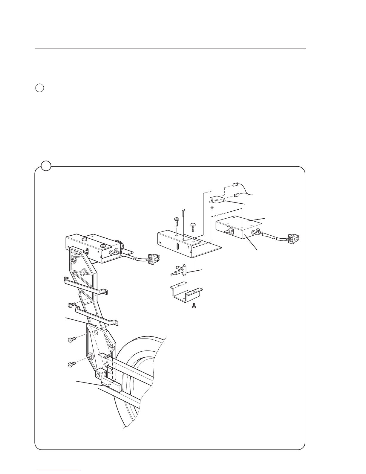
Description
The machine door lock consists of the following:
• The locking unit, located behind the front panel below the detergent
dispenser. The unit consists of a solenoid which locks the door, and two
microswitches. Switch S4A indicates that the door is locked and switch
S3 indicates that the door is closed.
• The door lock control unit, located in the automatic control unit. This unit
consists of a circuit board for monitoring door lock functioning.
• The locking arm, located between the door lock handle and the locking
unit. This arm provides the mechanical link between door lock handle
and locking unit.
Locking unit
Locking arm
Door lock
handle
Rocker arm
Safety switch S3
101640
101637
48
Fig.
48
Actuator
Switch
S4A, B
Page 39

39
Mechanical and electrical design
4697
Fig.
49
X96 X95 X94 X93 X99 X98 X97
X90
X91
X92
Door lock control unit
Red LED,
an indicator
Relay RE3
49
Door lock control unit
The sole function of this control unit is to oversee the correct functioning of
the door lock. The CPU board receives information from the motor control
unit about motor rotation, and has its own level-monitoring device. The
control unit also detects water level and motor speed through separate
level measurement devices and the rotation guard (speed-monitoring
device). Through this double monitoring, a very high level of safety can be
achieved.
When the CPU board commands door locking, the control unit checks that
there is no water in the drum and that the drum is not rotating. Only after
that is a signal sent to the door lock. Level and rotation are checked in the
same way before the door is allowed to open.
For even greater safety, the voltage feed to the I/O boards’ outputs goes
via both the emergency stop and the door lock switch. This means that no
functions can proceed unless the emergency stop is in its normal position
(not actuated) and the door is locked.
Page 40

40
Mechanical and electrical design
Meaning/cause
Level-sensing device indicates water in drum
when door lock is open. 2.19 Hz
Auxiliary relay for motor indicates that the motor
contactor is activated when the door lock is open
(this error indication pattern does not occur when
the excess-speed-monitoring device is selected).
1.88 Hz
Signals from rotation sensor and auxiliary relay
do not correspond. 1.56 Hz
The control unit sensor circuits indicate fault/
error in drive circuits for door lock including its
wiring. 0.85 Hz
Armament circuits for RE1/RE2 activated
(capacitor C8 charged when it should be
discharged). 0.37 Hz
LED pattern of flashes during normal functioning
Pattern of flashes indicating “OK”, drum at standstill
Pattern of flashes indicating “OK”, drum rotating,
5 Hz
Error indication pattern
4686
Fig.
50
50
Error indication patterns
If the door lock is working correctly, this is indicated by the red LED, by a
pattern of flashes which indicates “OK”. The error indication patterns revealed by the LED flash at various frequencies for the various errors or faults.
All error indication patterns have a frequency cycle of 50%, i.e. the LED will
be on half the time, off half the time.
1 second
Page 41

41
Program control unit
Control system transformer T10
The control system transformer is used to provide the voltage feed for the
circuit boards. The transformer supplies 12 V on its secondary side, and
can be adapted to suit any of four different primary voltages by moving a
strap.
The transformer should normally be connected for a primary voltage of
230 V. Switching for different power supply voltages takes place at
transformer T1.
Fig.
51
51
4746
240 V
230 V
208 V
120 V
Mechanical and electrical design
Page 42

42
Imbalance switch
Description
The imbalance switch is a safety feature which protects the machine from
damage during extraction caused by uneven distribution of the wash load.
The imbalance switch consists of a microswitch and a switch arm, mounted
on the left-hand front pillar of the frame. If the inner frame moves outside a
certain range, it will actuate the microswitch via the switch arm. As a result,
extraction will be halted and the PCU will switch to wash speed. After that
the PCU switches to distribution speed, before another attempt at
extraction.
If the imbalance switch is being triggered repeatedly, possible causes are:
• Unsuitable wash loads.
• The dampers are in poor condition, see Chapter 43. Frame.
• High water level not programmed for extraction.
60
40
60
95
60
40
30
Switch arm
4752
Fig.
52
52
Microswitch
Mechanical and electrical design
Page 43

43
Mechanical and electrical design
Motor
Description
The motor is mounted inside a motor mounting unit beneath the outer
drum. It drives the inner drum via a drive belt. The drive belt tension is
adjusted with the aid of two retaining screws on the side of the motor
mounting unit. See the section “Belt tension” in this chapter.
Electrical connection for the motor is by quick-connector.
This is a frequency-controlled motor, and its speeds for normal action,
distribution and extraction are controlled by E10, which is a
microprocessor-based motor control unit in the automatic control unit.
The motor windings have overload protection in the form of a thermal
protection device which resets automatically.
Fig.
53
53
4740
Page 44

44
Mechanical and electrical design
Motor control unit E10
X301
X304
X308
X302
LC2
X312
X311
54
Fig.
54
4744
LC2 Suppression filter
Connectors
X301 Serial communication with PCU
X302 Input, lock sequence
X304 Relay output
X308 Imbalance input
X311 Main input
X312 Connection, motor and thermal protection device (Klixon)
Page 45
45
Mechanical and electrical design
Motor control unit
The motor control unit communicates with the PCU board via a serial
duplex interface. With the aid of the MCU, the PCU board can not only
control the speed the motor is to have at any given moment, but also control
the acceleration and deceleration rates the motor will use to reach the
speed commanded. The MCU constantly relays information back to the
PCU board on current operating status, e.g. whether everything is
proceeding without problems or if a fault or error has arisen.
The MCU can also supply data on the torque of the motor at constant speed
and when accelerating and decelerating. This data is used both for
calculating the weight of the wash load and for detecting any imbalance
present.
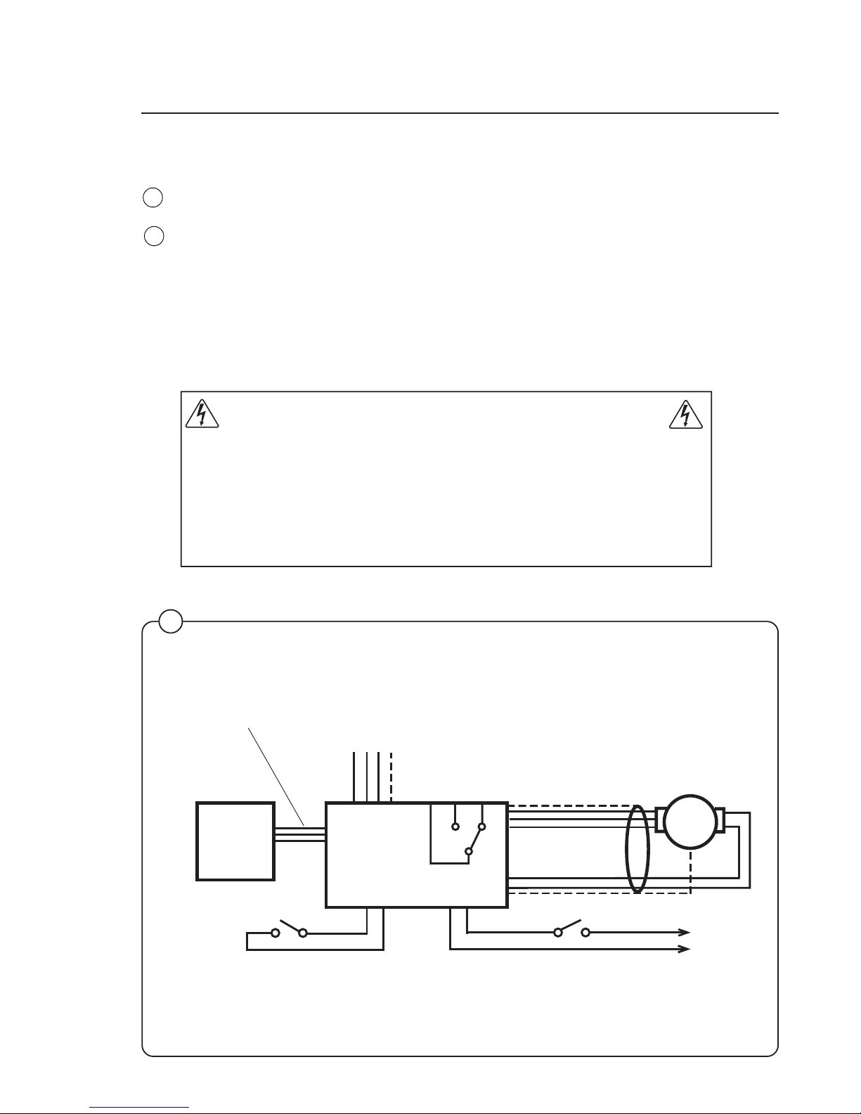
WARNING
Take great care when using measuring instruments on the MCU,
since all components have a potential difference of approx. 300
V in relation to earth and neutral.
The MCU will not be de-energised until 10-30 seconds after the
machine is isolated from the power supply and the motor has
stopped.
The green LED on the MCU board will remain lit for as long as
there are hazardous voltages present in components.
4711
Fig.
55
Fig.
57
55
230 V AC
Door lock switchImbalance switch
Imbalance
input
X308
Input
lock sequence
X302
Relay output
X304
Motor
Serial communication
X301
Main input
X311
PCU
X312
X312
Motor
control unit
Page 46

46
Mechanical and electrical design
For the 220 l machine there is a cooling fan on the MCU, on account of its
higher wattage. The fan starts up automatically when the heat sink reaches
a temperature of approx. 65°C, which can arise during extraction if the load
is unfavourable or if the ambient temperature is high. When the machine
power supply is first switched on the fan operates for a short time.
The MCU has an interlock signal input connected to a switch in the door,
which supplies the input with main voltage when the door is locked.
PCB connector/Function
X301: Serial communication
Communications between MCU and PCU. With an interface it is
possible to connect a PC for testing machine operation/functions.
X 301:2 Gnd
X 301:3 Txd
X 301:4 Rxd
X302: Input lock sequence
An input voltage of 96-276 VAC is required to start the motor.
The function of this input is to stop/not start the motor when the door
lock is open.
Input voltage: 120 V-20 % (=96 V) - 240 V+15 % (=276 V), 50/60 Hz
Current: Max. 0.01 A
X304: Relay output
The relay is controlled via commands from the PCU (X301). The relay is
not to be activated if communication with the PCU is lost.
Isolation voltage: 3750 V
Voltage: 250 VAC
Current: max. 2 A
Relay connections: 1-pole, 2-way (three connections)
Connector: X304:1 Normally open
X304:2 Normally closed
X304:3 Common
X307: Internal
For 220 l machines, this contact is used for connection of a fan for
cooling the MCU.
Page 47

47
Mechanical and electrical design
X308: Imbalance input
The function of the imbalance input is to stop the motor if the drum’s
movement is too great. (The imbalance switch is normally open.) When
the imbalance switch is activated (closes) a voltage of 96 - 276 V AC is
supplied to the MCU. The MCU detects that imbalance has arisen and
stops the motor.
Input voltage: 120 V-20 % (=96 V) - 240 V+15 % (=276 V), 50/60 Hz
The imbalance input receives its supply from Input lock
sequence (X302).
Current: Max. 0.01 A
X311: Main input
Input voltage: Single-phase or DC three-phase: 200 V-15%(=170 V) 240 V+10% (264 V)
X312: Output to motor and input thermal protection device (Klixon)
The output is connected to a thermal protection device, located on the
motor windings, with a connection back to the input. If the motor
becomes overheated, the thermal protection device switch opens. The
yellow LED reveals an error code through its pattern of flashes, see the
section “Error indication patterns”.
Current, max. 0.01 A
Page 48

48
Mechanical and electrical design
Fig.
56
1
2
3
4
5
6
7
8
9
10
11
approx. 5 seconds
4710
LED pattern of flashes Error code/message
on display Cause
31E Heat sink on MCU too hot.
32E Motor thermal protection device activated
33E MCU has received start command,
but not received interlock signal.
13E Communication error MCU – PCU
- Short in motor windings, wiring or internally in MCU.
MCU will restart automatically.
35E Once again short in motor windings, wiring or internally
in MCU.
36E Fault in interlock circuits in MCU.
37E MCU DC voltage too low.
38E MCU DC voltage too high
39E Ripple DC-bus (EWD 4000 only).
41E Fault/error in MCU overheating circuits.
56
Error indication patterns
If a fault or error occurs in the motor or motor control unit, the MCU sends
an error signal to the PCU board. In addition to an error code showing on
the display, errors/faults are revealed by the flashing of a yellow LED on the
MCU board. The table below shows how to identify the error/fault on the
basis of the flashing pattern of this LED.
Fig.
57
Page 49

49
Mechanical and electrical design
Pattern indicating “OK”
Flickering when MCU current-limiting
function is activated.
approx. 5 seconds
4712
Fig.
58
58
57
4708
Yellow LED
Green LED
X301
X302
X304
X308
X311
X313
X312
Fault-finding
There are fault-finding charts for all error codes.
Error indication patterns, green LED
The green LED on the MCU board is normally lit except for a brief pause
approx. once every five seconds (pattern which indicates “OK”).
When the microprocessor for the PCU is removed from the machine or has
reset status, the LED will be lit without flashing.
When the MCU current-limiting function is activated, the LED will instead
flicker, and the flashing pattern which indicates “OK” will be suspended for
as long as the current-limiting function is activated. When the MCU currentlimiting function ceases, the pattern of flashes indicating “OK” will return
after 10 seconds.
Page 50

50
Mechanical and electrical design
Extraction
During extraction, the motor speeds follow an extraction sequence which is
always the same. This extraction sequence is used for all WE/MP machines
and for standard programs 991-999 for CLARUS machines.
The table shows the extraction speeds during the various phases of the
sequence, for various drum volumes.
The extraction sequence is as follows:
Phase 1. Distribution period of 40 seconds, with imbalance
sensing. Imbalance sensing takes place during the
last 5 seconds.
Phase 2. Extraction for 30 seconds.
Phase 3. Extraction for 30 seconds.
Phase 4. Extraction for 30 seconds.
Phase 5. Extraction for remainder of the program’s total
extraction time.
59
4759
rpm
seconds
Imbalance sensing
Fig.
59
EX-30 S EX-50 S
Phase 1 85 78
Phase 2 475 425
Phase 3 650 550
Phase 4 800 700
Phase 5 950 850
Drum
volume
l
Speed
rpm
50
150
250200100
1000
800
600
400
200
0
0
1
2
3
4
5
Drum
volume:
EX-50 S
EX-30 S
Page 51

51
Mechanical and electrical design
Imbalance measurement
At the start of every extraction sequence the system monitors variations in
the motor torque while the drum is operating at distribution speed. If these
variations are too great, it indicates that the load is unevenly distributed in
the drum. At this point extraction is halted, the motor speed is reduced to
wash speed and a fresh attempt to begin extraction starts. This procedure
will be repeated up to three times per extraction. After the third time the
system will decide whether the imbalance is “great” or “small”.
• If the imbalance is “great”, the extraction stage of the program will end
without extraction having taken place.
• If the imbalance is “small”, extraction will take place, but at a reduced
speed.
Page 52

52
Belt tension
The tension of the drive belt is preset at the factory.
When checking belt tension, or after replacing
components which affect belt tension, follow the
instructions contained in the illustrations.
Correct belt tension is important. The
tension should always be checked as part
of service and maintenance.
Mechanical and electrical design
60
4741
X = 7 mm when belt is new.
Max. 9 mm on subsequent
checks of same belt. If X = more
than shown here, increase belt
tension.
F = 30 N (EX-30 S)
F = 40 N (EX-50 S)
7 mm
Max. 9 mm
Fig.
60
61
Retaining screw for
adjusting drive belt
tension
Retaining screw for
adjusting drive belt
tension
Fig.
61
4832
Page 53

53
Drain valve
Description
The drain valve is a motor-operated diaphragm
valve which allows rapid emptying thanks to its
large cross-section. This is a self-clearing design,
so there is no need for a lint filter.
Main parts of the valve:
• motor plus gear
• piston rod with trapezoidal thread, plus piston
and return spring
• rubber diaphragm
• connections for water filling, overfilling, drain
In its open state, the valve is not energised. In
this state the piston rod is screwed down to its
lowest position by the return spring. The
diaphragm is pressed downwards with the piston
and the valve is open.
62
Fig.
62
4748
4747
Nipple for sensor hose
for level control
Riser to wash
drum
Connection for
water filling
Diaphragm closed
position
Diaphragm open position
Piston rod
Guide pin
Motor Gear wheel
Return spring
Fig.
63
63
Mechanical and electrical design
Page 54

54
Mechanical and electrical design
Fig.
64
When the motor is activated and begins to rotate, the piston rod is turned
upwards via the gear, the diaphragm is pressed upwards with the piston
and presses against the valve seat: the valve closes.
The connection for overfilling is connected to the upper part of the wash
drum, water and foam are diverted straight to the drain if the intake valves
or level control should malfunction.
On the riser for the wash drum are the connection for water filling and a
nipple for connecting the sensor line for the level control.
Instructions for repair
Deposits on the diaphragm can prevent the valve from opening or closing
properly. The valve should therefore be cleaned at certain intervals,
depending on operating conditions and water quality.
If the valve is not opening or closing properly:
• Check that the motor has the right input voltage.
• Check that the piston rod can move freely.
• Check whether the diaphragm is clogged with deposits.
To note if replacing the motor:
Brown cable: 60 Hz
Blue cable: common
Black cable: 50 Hz
Page 55

55
Mechanical and electrical design
Pin of
return spring
Tongue of spring
Stop screw
4749
64
Tensioning of return spring
With the valve housing removed:
- Turn the return spring so that the “tongue” of the spring is resting against
the stop screw.
- Position the valve housing over the return spring so that the pin on the
spring will fit into the recess on the piston rod. (Note: the piston rod
should be installed so its recess is aligned along the housing.)
- Then turn the housing one turn clockwise. (This will screw the pin of the
spring into the piston rod. The spring will be now tensioned approx. 1/4
of a turn on account of the lead in the piston rod.)
Page 56

56
Mechanical and electrical design
Heating
Description
The machine elements are in the lower part of
the outer drum, accessible from the machine
front. They are switched in by heating relays,
controlled by the program control unit. For input
voltage 400-440 V one heating relay is used
(K21), and for 208-240 V, two are used (K21 and
K22).
The program control unit prevents the elements
from being switched in when there is no water in
the drum. If some fault should arise which
causes the elements to heat with no water in the
drum, their own fuses will blow.
Fault-finding
To be carried out by authorised personnel
only.
If heating time is abnormally long:
• Check with a multimeter to see if one of the
elements is burnt out. For access to the
elements, remove the machine’s front panel.
• Build-up of limescale can reduce the
efficiency of the elements. If necessary
descale them with a suitable descaling
product. Follow the manufacturer’s
instructions concerning quantity of descaler.
65
4728
4742
66
Sensor,
thermostat
Element
Fig.
65
Fig.
66
3AC
3
53
1
6
42
K21
53
1
6
42
K22
S1
L1
S1
L2
S1
L3
E1E3
S1
L1
S1
L2
S1
L3
3N
EL
5
K21
31
642
E1E3
3NAC
Page 57

57
Mechanical and electrical design
To replace an element
• Switch off the power supply to the machine at the main switch/wall
switch and check that the machine is isolated from the power supply.
Remove the front panel.
• Note exactly how the elements electrical connections are arranged, then
disconnect them.
• Undo the nut between the element’s connections and turn the screw a
half turn.
• Remove the inspection cover in the inner drum. Turn the drum so the
opening is at the bottom. This will give access to the nut for the element
holder through the opening. Release the nut for the element holder
enough to allow the element to be pulled out.
• Guide the new element into the element holder at the rear of the drum,
turn the screw one half turn and tighten the nut.
• Connect the element’s electrical connections.
• Tighten the nut on the element holder.
Refit the inspection cover.
• Fill the machine and check that there are no leaks from the element
seal.
Page 58

58
Mechanical and electrical design
Scale unit
4809
67
Load cell
Weighing equipment
Description
The weighing equipment comprises the following
units:
• A scale unit located inside the machine’s right
side panel
• Four load cells, one in each corner of the frame
• Wiring
The weight of the wash load is registered by the
four load cells, which send analogue signals to
the scale unit. In the scale unit the signals are
processed and converted to a weight value in an
analogue-digital converter. The weight value is
transmitted via a serial interface to the CPU
board. The weight is then shown on the display.
Weighing the load allows the water level to be
adjusted automatically according to the actual
weight of the load, i.e. the water level is reduced
during washing if the machine does not have a full
load. The consumption of water and energy can
thus be reduced.
Safety rules
The weighing equipment is a precision measuring
device and must be treated as such.
• Never spray water directly onto the load cells
and scale unit.
• The load cells are vulnerable to impact.
• The load cells are potentially vulnerable if
welding is carried out. If welding has to be
done on the washer extractor, attach the earth
cable clamp as close as possible to the
welding site.
After a power-cut
When the power is restored after a power-cut, the
weight displayed will always be 0, no matter
whether there is a load in the drum or not. If this
happens, it is important that you use the “Reset
weighing equipment” function via the Clarus
software. Follow the instructions under “Reset
weighing equipment” in the “Machine operation”
section of the manual.
After a power-cut, the weighing equipment
will always display 0, no matter what the
actual load in the drum. In this event you will
have to use the “Reset weighing equipment”
function.
Fig.
67
Page 59

59Mechanical and electrical design
Inlet valve, detergent
Construction
The valve has a single-inlet with either one, two
or three outlets, each with its own solenoid coil.
The body is made of heat-resistant polyamid
plastic and the solenoids encased in water-tight
plastic.
A filter screen on the inlet side prevents dirt from
entering the valve. Flow restrictors can be placed
at either the inlet or any of the outlets.
Operation
When the solenoid is energized, the springloaded plunger is drawn up and the pilot valve in
the center of the diaphragm open. Because of
the difference in diameter between the pilot valve
opening and the ventilating hole in the diaphragm, the pressure above the diaphragm drops
to a point where the admission pressure below
the diaphragm can lift the diaphragm, thus opening the valve.
When the current to the solenoid is cut off, the
plunger spring will press the plunger against the
pilot opening of the diaphragm. The pressure
above the diaphragm then rises to correspond to
the water inlet pressure and the pressure of the
spring will close the valve.
1161
1185
solenoid
plunger
ventilating hole
diaphragm
pilot valve
Fig.
68
Fig.
69
69
68
Page 60

60 Mechanical and electrical design
1181
1186
1187
Maintenance instructions
Lime scale can block the hole in the valve diaphragm and interfere with the function of the valve.
It is therefore advisable to disassemble and clean
the valve at certain regular intervals. The frequency depends on operating conditions and the
level of contamination in the water.
Trouble shooting
If the valve does not open
• Check that power is supplied to the coil.
• Check the coil with an instrument to determine
whether there is a break or a short circuit.
• Disassemble the valve (see below) and check
the openings in the valve diaphragm.
• Check the inlet strainer and clean as required.
• Undo the coil and clean the surfaces of the
magnetic core.
If the valve does not close
• Check that the coil is not live. The valve is
normally closed when the magnet is not
energised.
• Check the return spring.
• Check the diaphragm (pilot pressure opening).
Disassembling the valve
• Pull the coil straight upwards. Use a screwdriver if necessary to carefully undo the coil.
• Use the tool supplied with the machine
(attached to one of the hoses when the
machine is delivered) to open the valve
housing. Slide the tool over the protruding
plastic sleeve to that the pegs on the tool
engage the corresponding sockets in the
valve housing.
• Use a wrench or a pair of pliers and unscrew
the upper part of the valve housing.
ventilating hole
pilot valve
Fig.
70
Fig.
71
Fig.
72
72
71
70
Page 61

61Mechanical and electrical design
Inlet valve
The water inlets have brass bodies with larger
cross section of the outlet in order to achieve a
shorter filling time for the machine.
Construction
The valve housing is made of pressed brass. The
spring-loaded plunger is made of stainless steel
and located at its lower end.
Operation
The valve is automatically operated by means of
a rubber diaphragm and a pilot valve in exactly
the same way as the supply injector valve.
To strip, clean, re-assemble and
troubleshoot the inlet valve, follow the
instructions outlined for the supply injector
valve.
Fig.
73
73
3963
74
3961
Fig.
74
Coil
Spring
Plunger
Diaphragm
Body
Page 62

62 Mechanical and electrical design
Soap supply box
The three-compartment soap supply box is located at the top of the machine.
Viewed from the front, the compartments marked with figures 1, 2 and 3 are
used as follows:
Compartment 1
This compartment is used for adding detergent at the beginning of the
Prewash cycle. Powders may be loaded immediately; for liquids, wait until
the display shows an arrow and the compartment flushes with water.
Compartment 2
This compartment is used for adding detergent at the beginning of the Wash
cycle. If bleach is used, it is added to this compartment when the display
arrow appears.
The insert is used to help prevent oversudsing.
Compartment 3
This compartment is used for liquid fabric softener, which is siphoned into
the drum at the start of the third rinse. Liquid softener may be added at the
beginning of the cycle or during the final rinse when the arrow appears.
75
Fig.
75
1182 b
Page 63

63Mechanical and electrical design
Drain valve
Description
The drain valve consists of a bracket (1), on
which are mounted the motor and gear (2) and
diaphragm (3). The rubber diaphragm is resistant
to a water temperature up to 100°C (212°F). The
installation of a lint trap is not necessary. The
machine is equipped with an overflow, which
bypasses the drain valve. The drain can be
cleaned by removing the drain connection (4)
outside of the machine or by removing the rubber
diaphragm (3). The motor and gear assembly is
covered by a plate and provided with quickdisconnect electrical connections. The stator coil
is constructed for continuous operation.
Operation
The drain valve is normally open, i.e. the motor
does not close the valve until it receives current
via a contact of the timer. As soon as the current
is cut, the shaft turns and opens the diaphragm
of the valve. This also permits the machine to
drain, in the event of power failure. The overflow
hose (5) leads excess water or suds directly to
the waste line, in the event of failure in the inlet
valves or level control.
Trouble-shooting
If the valve does not open or close properly:
1. Check that the shaft is moving freely.
2. Check that the diaphragm is not obstructed.
3. Check the coil for continuity.
Clean out
Periodic cleaning of the valve is recommended,
depending upon how often the machines are
used, as well as the type of wash handled most
frequently.
76
Fig.
76
0313
Page 64

64
Mechanical and electrical design
Electronic program control unit
Description
The program control unit is electronic and consists of a circuit board with
components. On one half are the microprocessor, program memory
(EPROM), power supply circuits, temperature and level control devices and
so on. On the other half are the relays and interference suppression
components. The program control unit has the following inputs and outputs:
• Inputs reacting to push-buttons on the control panel.
• Inputs which provide information on the machine’s door lock status, level
control, temperature sensors and coin mechanism if installed.
• Outputs which via relays directly control the various functions of the
machine, e.g. motor control, water valves and door lock.
• Outputs to the display.
• Serial communication with the motor control unit.
The program control unit is controlled by the microprocessor, which fetches
its instructions from the program memory (EPROM). The EPROM contains
instructions for operation, the service program, control of relays, sensing of
inputs etc. The EPROM also contains the standard programs supplied with
the machine.
Fig.
77
X74
Temperature
sensor
X75
Motor control
unit
X76
Price = zero
X80
Valves
X81
Valves
X82
Valves
X83
Heating
X84
CP80
X71
Door lock
X72
Voltage feed
F1 (1A/250V)
For electronics
Buzzer
Microprocessor
Relays
Program memory (EPROM)
Level sensing
device
Service switch
2316
X79
Drain
X78
Input voltage
Interference
suppression
components
To
control
panel
X77
Coin mechanism
F2, F3 (1A/250V)
For display
77
Page 65
65Mechanical and electrical design
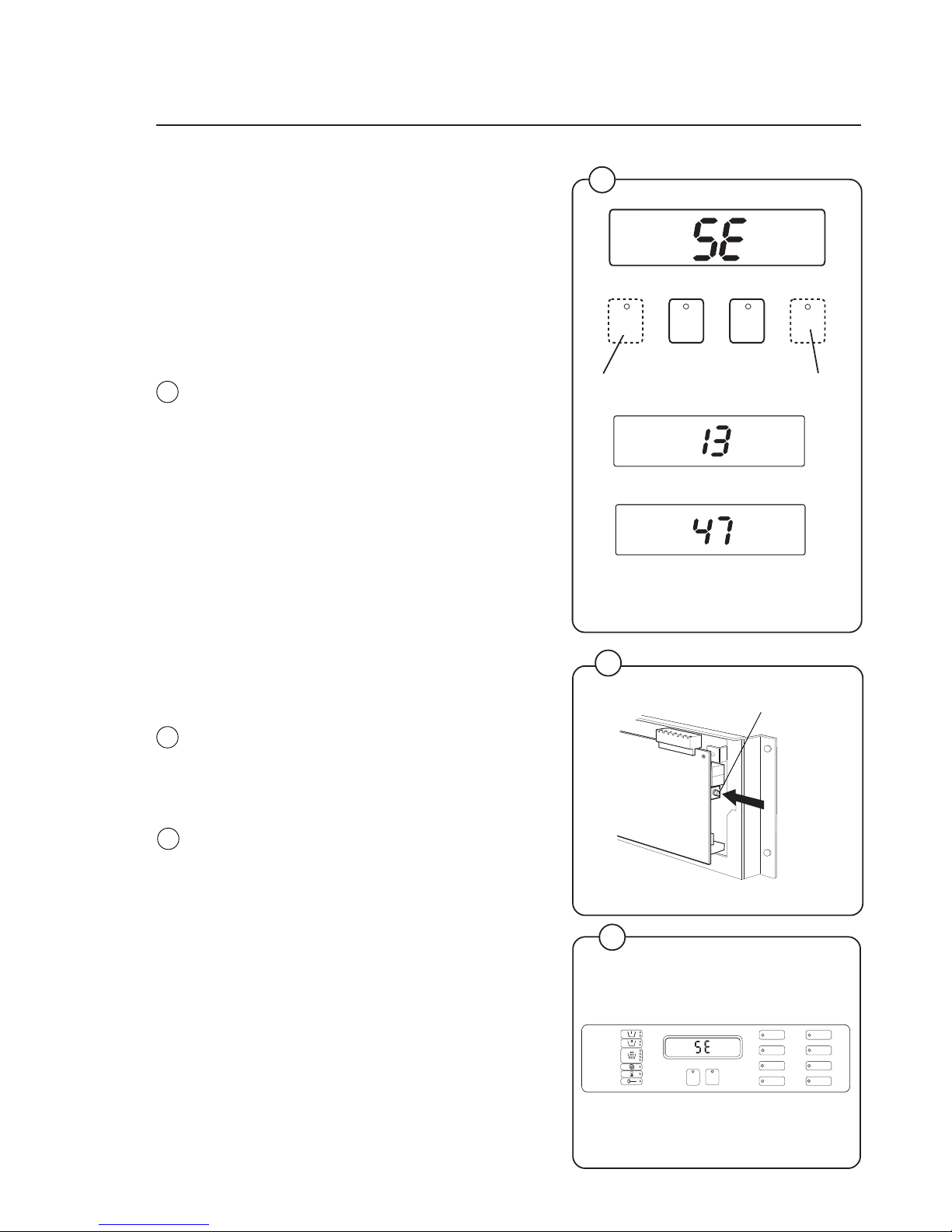
Operating time, accumulated coin value,
EPROM no.
The machine’s built-in service program can be
used to check the machine’s accumulated operating time, the accumulated coin value (for coinoperated machines), and the program EPROM
part number.
Accumulated operating time
To check during normal operation
The machine needs to be actually operating
(program selected and started).
The buttons identified as A and B in the illustration
may be ”concealed” on some machines, in other
words, have no symbols or other markings. They
will still be usable for this function, however.
Press button A. The first two digits of a four-digit
number will now be displayed, e.g. 13.
Press button B. The last two digits of a four-digit
number will now be displayed, e.g. 47.
This means that the machine’s accumulated
operating time is 1,347 hours.
To switch on service mode
• Remove the machine top and the cover for the
program unit circuit board.
• Press the service switch. This switch is on the
left-hand edge of the circuit board when viewed
from the machine front. The display will now
show SE, which means that the service program is activated.
Now some of the buttons switch to being number
keys (1 to 9). The start button becomes an ON/
OFF key.
To switch off service mode
Press the service switch again, or switch off the
machine power supply.
80
A
1
1
4
3
2
6
5
8
7
9
3385
3400
78
2242
2241
2224
A
+
B
AB
1,347 hours’ operating time
=
79
Fig.
79
Fig.
80
Fig.
78
1
2
Service switch
Page 66
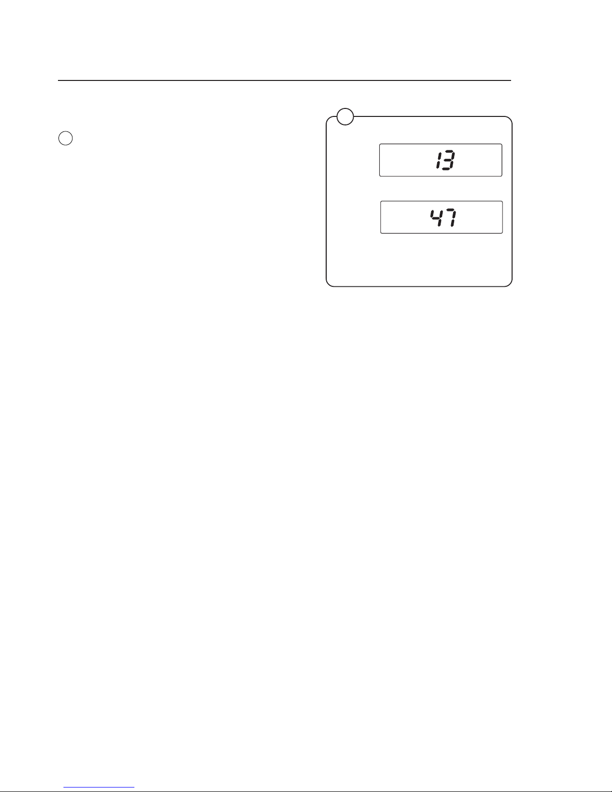
66 Mechanical and electrical design
To check in service mode
Enter code 43. The first two digits of a four-digit
number will now be displayed, e.g. 13.
Enter code 44. The last two digits of a four-digit
number will now be displayed, e.g. 47.
This means that the machine’s accumulated
operating time is 1,347 hours.
Fig.
81
2242
2241
Code 43
Code 44
1,347 hours’ operating time
81
+
=
Page 67

67Mechanical and electrical design
To check in service mode
Enter code 41. The first two digits of a four-digit
number will now be displayed, e.g. 06.
Enter code 42. The last two digits of a four-digit
number will now be displayed, e.g. 58.
This means an accumulated coin value of 658
currency units or 658 tokens. In other words, it
shows that 658 currency units or tokens have
been inserted into the coin mechanism up until
the time of the check.
Fig.
82
+
=
2239
2240
Code 41
Code 42
658 currency units/tokens
82
Page 68

68 Mechanical and electrical design
Program EPROM part no. (check in service mode)
Enter code 51. The letter A and two digits will be
displayed, e.g. A47. ”A” denotes part no. (article
no.).
Enter code 52. The display will show (e.g.) 195.
Enter code 53. The display will show (e.g.) 803.
Enter code 54. The display will show (e.g.) 480.
When these digits are put together they make up
the full part number:
A471 958034. The two digits at the end are an
internal version number.
+
+
+
=
2235
22362237
2238
A (=part no.)471 958034
80 (code 54) = internal
version no.
Code 51
Code 54
Code 53
Code 52
83
Fig.
83
Page 69

69
Mechanical and electrical design
Level control
Description
The "level control", which is located on the circuit
board, is a pressure switch which monitors the
different water levels in the drum by sensing the
air pressure in a tube which is connected to the
bottom of the drum. As the water rises in the
drum, the air inside the tube is compressed and
at a set pressure ("cut-out-level") the micro-processor cuts out water filing.
When the water is emptied from the drum the
microprocessor switches back to the starting
position again, but now at lower water levels than
were needed to switch when the drum was filling.
These levels are called "on-levels". If during a
wash the water should sink below on-level, the
machine will be filled with water again, to cut-outlevel.
Checking functioning and fault location
To be carried out by authorized personnel
only.
A faulty level control cannot be repaired. Instead
the whole circuit board must be replaced.
To check functioning of the level control
• Start the service program by pressing the
service button. Now certain of the buttons
switch to being number keys (1 to 9).
• Enter code 24. Now the display will show the
current level in the machine on a scale of 1 to
200. An empty machine should show a value
between 0 and 4.
• Press the START button. The machine will
start to fill.
• Check that the figure shown on the display is
counting upwards as the water level rises.
• After completing your check, stop filling by
pressing the START button.
• Enter code 21 and open the drain valve to
empty the machine.
• Quit the service program by pressing the service button.
If machine is filling to a level which is too high:
• Check that the tube between the level control
and drum is not blocked. If necessary clean it
by disconnecting it at the level control end with
no water in the machine and blowing it clean.
• Check that the tube is undamaged.
• Test the machine by running a program.
Fig.
85
3400
3385
A
1
1
4
3
2
6
5
8
7
9
84
85
Fig.
84
Service switch
Page 70

70
Built-in service program
The machine has a built-in service program to
facilitate function checking and fault-finding.
This program may only be used by trained and authorized service personnel.
To switch on service mode
• Remove the machine top and the cover for
the program unit circuit board.
• Press the service switch. This switch is on the
left-hand edge of the circuit board when
viewed from the machine front. The display
will now show SE, which means that the
service program is activated.
Controls in service mode
Now some of the buttons switch to being
number keys (1 to 9). The start button becomes
an ON/OFF key. The various machine functions
can be tested using numerical codes (see table
on next page).
The LEDs to the left of the display show which
input signals to the program control unit are
active.
To switch off service mode
Press the service switch again, or switch off the
machine power supply.
3400
3385
3429
Fig
86
Fig
87
Fig
88
Fig
86
88
Service program
87
86
A
1
1
4
3
2
6
5
8
7
9
Service switch
Key switch for price = zero
Coin slot 1
Coin slot 2
Price programming button
Switch in door lock
Door status switch
Remote start, e.g. by external
timer
Page 71

71Service program
Error codes
Given below is a brief summary of all the error codes and their causes.
Error Code Cause
11 Detergent signal 1, liquid detergent.
12 Detergent compartment 2, cold water /Detergent signal
2, liquid detergent.
13 Detergent compartment 3, cold water /Detergent signal
3, liquid detergent.
14 Detergent compartment 2, hot water /Detergent signal
4, liquid detergent.
15 Detergent signal 5, liquid detergent.
16 Hot water in drum.
17 Detergent compartment 1, cold water.
18 Hard water in drum.
19 Heat: display shows actual temperature in drum, not
code 19. When ”START” is pressed, the heating relay
reacts if the water level is above 64 scale units. (Safety
level).
21 Drain valve/pump
23 Activate door lock. When it is deactivated, the water
drain valve will also open.
24 Level check. The parameter corresponding to the
actual level will be shown on the display, not code 24.
When ”START” is pressed, filling with cold water
commences via detergent compartment 1.
25 Motor, wash speed low (30 rpm), counterclockwise.
26 Motor, wash speed low (30 rpm), clockwise.
27 Motor, wash speed high (48 rpm), counterclockwise.
28 Motor, wash speed high (48 rpm), clockwise.
29 Distribution speed (90 rpm), clockwise.
31 Extraction, low (550 rpm), clockwise.
32 Extraction, medium (700 rpm), clockwise.
33 Extraction, high (1000 rpm), clockwise.
34 Extraction, high (1000 rpm), clockwise.
35 Display, test of segments, LED test, and buzzer.
36 Buzzer
Page 72

72 Service program
Error Code Cause
37 LED test
41-42 Coin mechanism (see Page 39, Program control
unit).
43-44 Counter (hours) for accumulated operating time (see
Page 39, Program control unit).
45 Last error code flagged.
51-54 Program EPROM part number (see Page 39,
Program control unit).
91 Coin value, coin slot 1. This is set using the price-
programming switch (see Page 39, Program
control unit).
92 Coin value, coin slot 2. This is set using the price-
programming switch (see Page 39, Program
control unit).
93 Availability of pause function in coin-operated
machines. Can be 1 = Yes or 0 = No. This is set
using the priceprogramming switch (see Page 39,
Program control unit).
94 Availability of rapid advance function in coin-
operated machines. Can be 1 = Yes or 0 = No. This
is set usingthe price-programming switch (see
Page 39, Program control unit).
95 Activate coin-op input. Can be 1 = Active or 0 = Off.
This is set using the price-programming switch (see
Page 39, Program control unit).
97 To program a price reduction on a coin-operated
machine, use the price-programming button. You set
a price reduction as a percentage between 0 and
99. Rounding-up will take place to the next coin
value upwards. A price reduction of 99% means a
free wash program.
Page 73
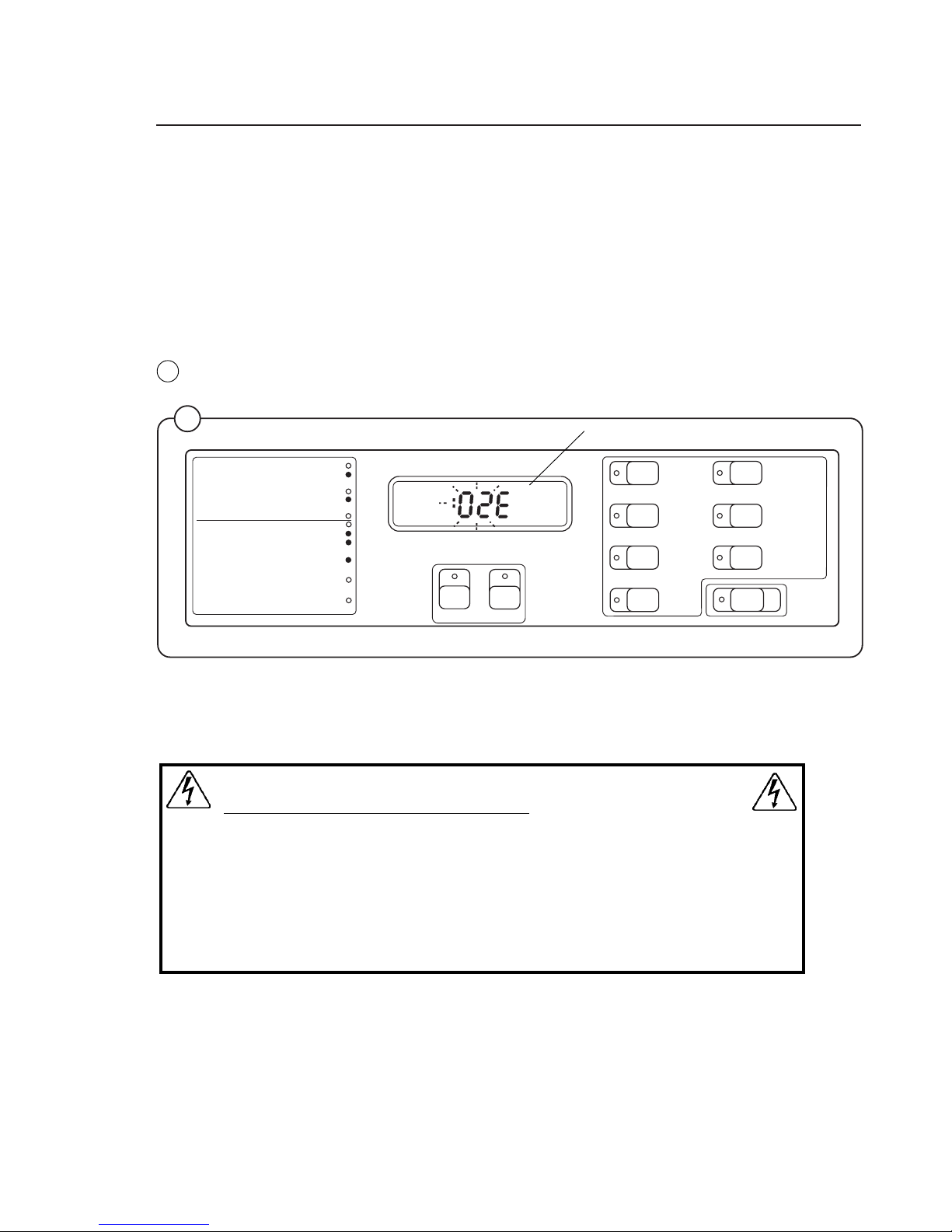
73
1
Supply
signals
A
B
2
3
4
5
START
STOP
6
1
Program
step
7
Final extract
Doorlock delay
Door unlocked
2
3
4
5
Prewash
Mainwash
Rinse
Trouble shooting
If the power supply to the machine should be cut while it is operating, the
program unit has a memory which stores the program selected for about 3
to 5 minutes.
Within this period the machine will restart automatically once the power
supply is restored.
Indication of faults/errors
Faults/errors in the program or machine are indicated by a numerical error
code followed by the letter E flashing on and off on the control panel
display.
In the case of error codes 01E, 02E, 03E and 14E, an attempt to restart the
machine may be made as soon as the fault/error has been remedied,
without the power supply being switched off. For the other error codes, a
service engineer must be called.
WARNING
When working on the motor control unit
The voltage at test points 1 - 4 (TP1 - 4) has a potential difference of
up to 300 V in relation to incoming neutral and ground. Because of
this, be careful when measuring. Use ungrounded oscilloscopes.
The motor functions as a generator when decelerating. If the motor
has not stopped, high voltages may be present on the motor control
circuit board even though the power supply to the machine has been
disconnected.
Trouble shooting
89
Fig.
89
4988
Error code
Page 74

74
Error codes
Given below is a brief summary of all the error codes and their causes. Starting on page 5 of
this section there are fault-finding charts for all error codes.
At the end of the chapter there are also charts for faults which do not generate error codes.
Error code Cause
01E Water level not reached within set time. Take necessary action. Press START again.
02E Door status switch open during program operation. Take necessary action. Press
START again.
03E The lock has not locked the door within the set time. Take necessary action. Press
START again.
04E The temperature sensor indicates temperature below -5°C (open circuit).
05E The temperature sensor indicates temperature above 98°C (short-circuit).
06E The water level is above the safety level set for starting.
07E The water level is above the safety level set for program operation.
08E Temperature increase in water less than 5°C/10 min. (Heated machines).
10E The water level is above the safety level set for after drain.
12E The program control unit cannot read the program EPROM.
13E Program control unit receiving no response from the motor control unit.
14E Level system not temperature-calibrated. Press START to run the wash program.
Program will run, but the water level will not be optimally adjusted.
17E Door status switch open, even though the door lock is locked.
43E Unbalance switch on when motor not rotating.
45E Tacho error
Trouble shooting
Page 75

75
Trouble shooting
Error codes which may arise on the control panel display
Error code/symptoms
Fault-finding Cause/Action
Check that the manual water valves (taps)
are open.
Taps turned on. Taps turned off.
Restart the program and use rapid advance to
get to main wash. Check that the machine is
filling with water.
Machine filling Machine not filling
Check input voltage on
relevant water valve (See
Program Tables, Chapter
4).
Voltage not Voltage
correct correct
Check water valve input
voltage at PCB connector
X80, X81a or X81b,
according to valve.
Voltage not Voltage
correct correct
Check input voltage
(230 V ) at PCB
connector X78.
Voltage not Voltage
correct correct
Check that the discharge valve is closed, i.e.
water level rising in drum.
Discharge valve closed Discharge valve open
Check that level tube is sound, not kinked, not
come loose from mother board.
Level tube OK Level tube not OK
01E
Acknowledgement signal for
water level not received within
time allowed.
X80
6 5 4 3 2 1
X81b
X81a
2 1 4 3 2 1
Y14 Y12 Y13
Y34 Y24 Y22
X78
2316
3331
2316
3350
Open taps. Press START
again.
Faulty valve. Check function
as described in Chapter 34.
Faulty wiring between
program control unit PCB and
water valve. Check wiring and
replace where necessary.
Faulty control output from
program control unit PCB.
Replace PCB.
Faulty wiring program control
unit PCB - transformer T10, or
faulty/incorrect strapping on
transformer T10.
Follow fault-finding procedure
for error code 06E in this
chapter.
Fit tube properly or replace it.
Level detection function on
program control unit PCB
faulty. Replace PCB.
Check voltage
Connection
level
tube
Page 76

76
Open door. Close door and try to restart the
machine.
Error code returns No error code
Set program control unit to service mode (see
”To switch on service mode”). The door status
switch will now be indicated by the LED
(illustrated).
Press in the door status switch manually and
check if this is indicated by the LED.
LED does not light. LED lights.
Disconnect the two wires from the switch. Shortcircuit the two wires.
LED does not light. LED lights.
Remove connector X71 from the program control
unit PCB. Short-circuit between inputs 3 and 4.
LED does not light. LED lights.
Trouble shooting
1
4
X71
2316
02E
Door status switch open
during program operation.
Check whether the pin on the
door or the plastic slide which
the pin presses against are
worn. Replace any worn
parts.
Continuity fault in wiring or
connectors. Check wiring and
replace if necessary.
Fault in program control unit
PCB. Replace PCB.
Shortcircuit
Door lock switch faulty.
Replace switch.
Cause/Action
Fault-findingError code/symptoms
Transient fault in door lock or
program PCB.
3430
LED
indicating
Door
status
switch
Page 77

77
Trouble shooting
Error codes which may arise on the control panel display
Open door. Close door and try to restart the
machine.
Error code returns No error code
Start service program and activate door lock
(code 23, press START). Check input voltage to
door lock, PCB connector X71 between terminals 1 and 2.
Voltage correct. Voltage absent or wrong.
Unscrew the door lock. Door and door lock).
Check voltage at door lock between terminals
X71:1 and 2 as illustrated.
Voltage correct. Voltage absent or wrong.
3390
1
4
Check
voltage
2316
Error code/symptoms
Fault-finding
Transient fault in door lock or
program PCB.
Faulty control output from
program control unit PCB.
Replace PCB.
Cause/Action
Faulty wiring between
program control unit PCB and
door lock. Check wiring and
change if necessary.
Faulty door lock. Replace
door lock.
X71
03E
The lock has not locked the
door within the set time.
Page 78

78
Trouble shooting
Error codes which may arise on the control panel display
Error code/symptoms
Fault-finding Cause/Action
Are there water in the drum?
Yes No
Disconnect the level tube
from the program PCB.
Turn the machine’s wall
switch off and on again.
Start a program.
Error code 06E No error
code or
error code 01E
Turn the machine’s wall switch off. Does water
run out of the drum?
Yes No
Turn on wall switch. Start a program and let it
run.
Still an error code. No error code.
Check to see if the discharge valve is partially
blocked or not opening fully.
Discharge valve OK Discharge valve not OK
06E
Water level signal above
parameter set, on program
start-up.
3350
Faulty control signal to
discharge valve from program
control unit PCB. Replace
PCB.
Connection
level
tube
Level tube probably blocked,
due to fluff of wrongly
mounted. Clean or replace
tube.
Nipple blocked on drain valve.
Check the discharge valve
(see Chapter 38). The service
program can be used (code
21) to open and close the
control valve for the discharge
valve.
Level sensing device on program
control unit PCB not working or
incorrectly calibrated.
Check zero level in the service
program see chapter 12 page 4,
code 24, zero level shall be
between 0 and 4.
Transient fault. No action
required.
Check to see if the discharge
valve is partially blocked or
not opening fully (see Chapter
38).
Page 79

79
Trouble shooting
Error codes which may arise on the control panel display
Error code/symptoms
Fault-finding
Cause/Action
Turn the machine’s wall switch off and on. Start
a program.
Error code 06 No error code
Is there a valve still drawing water?
Yes No
Turn the wall switch off
and on. Disconnect level
tube from level sensing
device on PCB. Start a
program.
Error 07 or No error
06 returns code
Remove connector for valve input voltage.
Valve stops drawing water.Valve still drawing
water.
3350
07E
Water level signal above
parameter set for safety,
during program.
Transient fault or water has
been added manually.
Connection
level
tube
Level tube probably blocked,
due to fluff or wrongly
mounted.
Clean or replace tube.
Nipple blocked on drain valve.
Level sensing device on program control unit PCB not
working or incorrectly calibrated.
Check zero level in the service
program, see chapter 12 page 4,
code 24, zero level shall be
between 0 and 4.
Faulty water valve. Clean or
replace valve (see Chap. 34).
Fault in control signal from
program PCB. Replace PCB.
Page 80
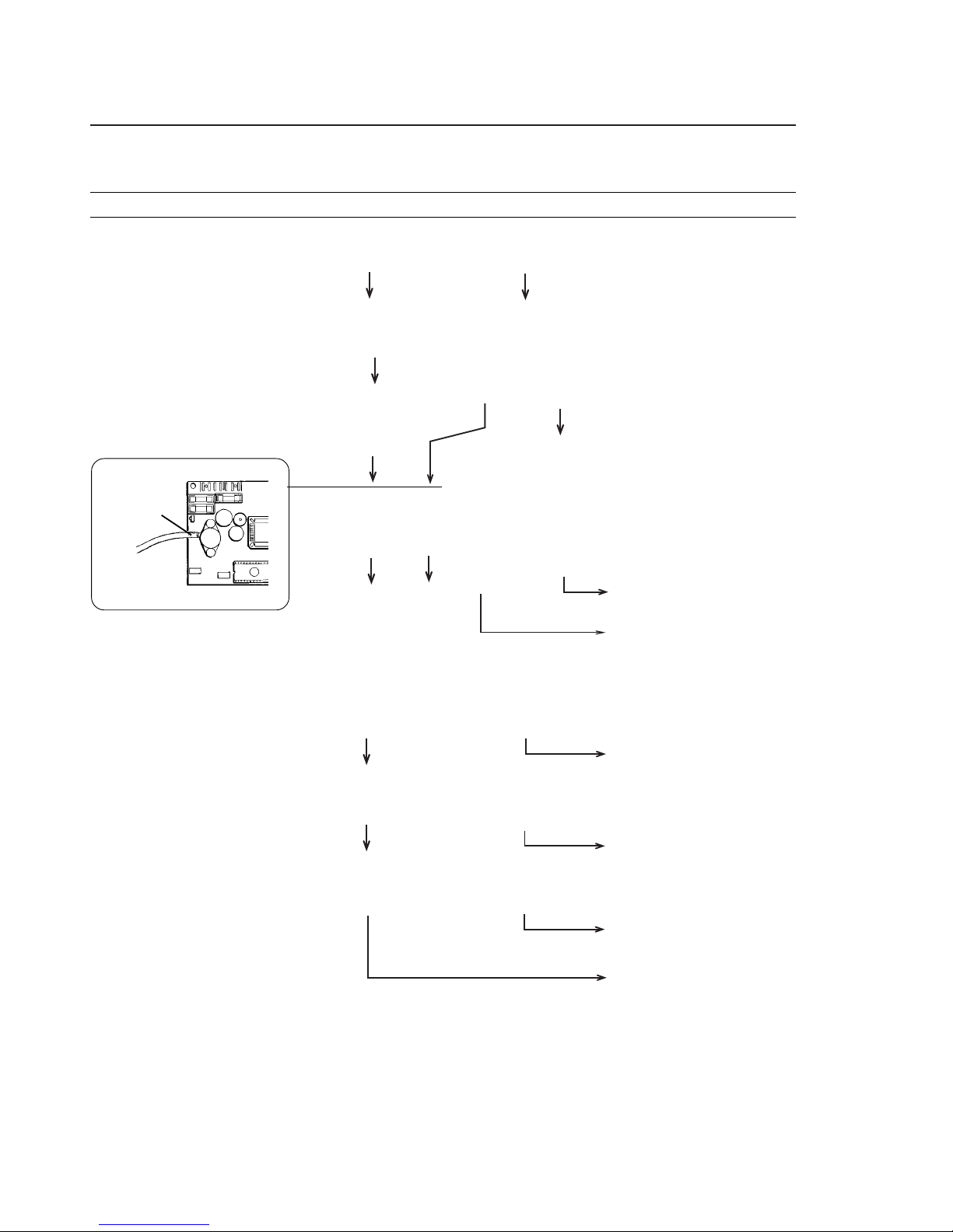
80
Trouble shooting
Error codes which may arise on the control panel display
10E
The water level is above the
safety level set for after drain.
Is water visible in the drum?
Yes No
Remove the water drain
valve from the drum. Is
there water at the bottom
of the drum?
Yes No
Disconnect the level tube
from the program PCB.
Turn the machine’s wall
switch off and on again.
Start a program.
Error code No error
06E or code or
error code error code
10E 01E
Turn the machine’s wall switch off. Does water
run out of the drum?
Yes No
Turn on wall switch. Start a program and let it
run.
Still an error code. No error code.
Check to see if the drain valve is partially
blocked or not opening fully.
Drain valve OK Drain valve not OK
3350
Error code/symptoms
Fault-finding
Level tube probably blocked.
Clean or replace tube.
Level sensing device on
program control unit PCB not
working or incorrectly
calibrated.
Transient fault. No action
required.
Faulty control signal to drain
valve from program control
unit PCB. Replace PCB.
Check the drain valve. The
service program can be used
(code 21) to open and close
the control valve for the drain
valve.
Cause/Action
Connection
level tube
Check to see if the drain
valve is partially blocked or
not opening fully.
Page 81

81
Trouble shooting
Turn the machine’s wall switch off and on again.
Start a program.
Error code returns No error code
Unscrew the program control unit PCB. Remove
the EPROM, then refit the same one. Check that
the EPROM is turned the right way and that all
its leg connectors enter the holder correctly.
Restart the machine.
Error code 12E returns Machine normal
Replace the EPROM. Check that the new one
has the correct program version. Restart
machine.
Error code 12E returns Machine normal
12E
The program control unit
cannot read the program
EPROM.
Error codes which may arise on the control panel display
2316
The marking
on the
EPROM
must be to
the left.
EPROM
Faulty program control unit
PCB. Replace PCB. The old
EPROM can probably be
reused.
Old EPROM was faulty.
Temporary loss of contact or
EPROM fitted incorrectly.
Transient fault. No action
required.
Cause/Action
Error code/symptoms
Fault-finding
Page 82

82
Trouble shooting
When START is pressed wash programs will
run, but the water level will not be optimally
adjusted.
Turn the machine’s wall switch off and on again.
Start a program.
Error code returns No error code
14E
Level system not temperature-calibrated
Error codes which may arise on the control panel display
Transient fault. No action
required.
Replace program control unit
PCB.
Cause/Action
Error code/symptoms
Fault-finding
Page 83

83
Trouble shooting
17E
Door status switch open,
even though the door lock is
locked.
Turn the machine’s wall switch off and on again.
Start a program.
Error code returns No error code
Set program control unit to service mode. The
door status switch and door lock switch will now
be indicated by the LEDs shown left. Follow this
procedure (the door can be locked using code
23 and one press of the START button):
Door Status of LEDs should be
for door lock switch: for door status
switch
open OFF OFF
closed, not locked OFF ON
closed and locked ON ON
Door lock switch LED ONDoor status switch LED
when door not locked OFF when door closed
Unscrew the door lock. Remove connection to
door lock switch "C" on door lock as illustrated.
LED ON LED goes out
Remove PCB connector X71 from program
control unit PCB.
LED ON LED goes out
Error codes which may arise on the control panel display
1
X71
Error code/symptoms
Fault-finding
2316
3390
Transient fault. No action
required.
Follow the chart for error code
02E to identify fault.
Cause/Action
Door lock faulty. Replace
lock.
Fault in wiring between PCB
and door lock. Check wiring
and replace if necessary.
Fault in program control unit
PCB. Replace PCB.
LEDs
indicating:
Door lock
switch
Door
status
switch
Page 84

84
Trouble shooting
20E
Interlock signal absent at
motor control unit during
program operation.
Error codes which may arise on the control panel display
Turn the machine’s wall switch off and on again.
Start a program.
Error code returns No error code
Check the voltage between terminals 1 and 2 at
PCB connector X302 on motor control unit. The
voltage should be 120/230 V when the door is
closed and locked.
Voltage wrong Voltage correct
Check the voltage between terminals 5 and 6 on
PCB connector X71 on program control unit
PCB. The voltage should be 120/230 V when the
door is closed and locked.
Voltage wrong Voltage correct
Check the input voltage to PCB connector X78
(120/230 V)
Wrong voltage Voltage correct
3333
1
X71
6
X78
2316
X302
Error code/symptoms
Fault-finding
Cause/Action
Faulty signal detection on
motor control unit. Replace
motor control unit.
Transient fault. No action
required.
Fault in wiring between
program control unit PCB and
motor control unit. Check
wiring and replace if
necessary.
Faulty wiring between
transformer T10 and program
control unit PCB. Check
wiring and replace if
necessary.
Faulty output signal on
program control unit PCB.
Replace PCB.
120/230 V
120/230 V
Page 85
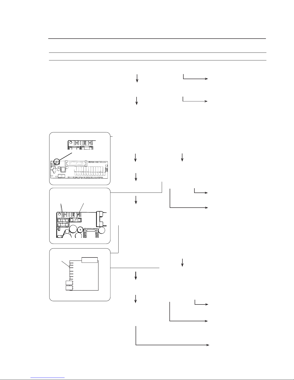
85
Trouble shooting
Turn the machine’s wall switch off and on again.
Fault persists. Machine working
Check fuses F11, F12, F21 and F22.
Fuses sound Fuse fault
Check that the input voltages to the PCB are
correct. Measure on PCB connector X72
between the following inputs:
X72:1 - 2 ca 1,75 V ~
X72:2 - 3 ca 1,75 V ~
X72:4 - 5 ca 14,5 V ~
X72:6 - 7 ca 13,5 V ~
An incorrect voltage Voltages correct
Check the three glasstube fuses on the PCB.
Rating: 1 A/250 V.
OK Fuse fault
Remove connector X172 on transformer T10.
Measure the voltages between the following
outputs on the transformer board.
5 - 6 ca 1,75 V ~
6 - 7 ca 1,75 V ~
3 - 4 ca 14,5 V ~
1 - 2 ca 13,5 V ~
Voltages correct An incorrect voltage
On T10 check the input
voltage at connector X178
(120/230 V) and that the
strap is correctly located
and in contact with the
circuit board.
OK A fault
Machine completely ”dead”.
Display blank.
1
7
X72
2316
F2, F3
Display
2316
3348
X172
1
7
Strap
PCB transformer T10
Error code/symptoms
Fault-finding
F1
Electronics
Transient fault. No action
required.
Change fuse(s) and check
functioning.
Change fuse(s) and check
functioning.
Replace program control unit
PCB.
Fault in wiring between
transformer and circuit board.
Check wiring and replace if
necessary.
Replace transformer T10.
Voltage fault: investigate
cause in power supply
beyond machine.
Cause/Action
X178
Page 86

86
Trouble shooting
Display blank, but machine is
working otherwise.
Turn the machine’s wall switch off and on again.
Fault persists. Machine working
Check glass-tube fuses F2 and F3 on program
control unit PCB. Rating: 1 A/250 V.
Fuses sound Fuse fault
Check that input voltages to PCB are correct. At
connector X72, measure between the following
inputs:
X72:1 - 2 ca 1,75 V ~
X72:2 - 3 ca 1,75 V ~
X72:6 - 7 ca 13,5 V ~
An incorrect voltage Voltages correct
Remove connector X172 on transformer T10.
Measure the voltages between the following
outputs on the transformer board.
5 - 6 ca 1,75 V ~
6 - 7 ca 1,75 V ~
1 - 2 ca 13,5 V ~
Voltages correct An incorrect voltage
F2, F3
Display
2316
1
7
X72
2316
3348
X172
1
7
PCB transformer T10
Transient fault. No action
required.
Change fuse(s) and check
functioning.
Fault in wiring between
transformer and circuit board.
Check wiring and replace if
necessary.
Replace transformer T10.
Program control unit PCB
faulty. Replace PCB.
Cause/Action
Error code/symptoms
Fault-finding
Page 87

Page 88

 Loading...