


WARNING: ALL OPERATING AND MAINTENANCE PROCEDURES SHOWN ON THE NEXT
PAGE OF THIS MANUAL MUST BE FOLLOWED DAILY FOR PROPER OPERATION OF
YOUR WASCOMAT MACHINE.
PLEASE ENTER THE FOLLOWING INFORMATION AS IT APPEARS ON THE MACHINE(S)
DATA PLATE(S).
MAKE CERTAIN TO KEEP THIS MANUAL IN A SECURE PLACE FOR FUTURE
REFERENCE.
MACHINE TYPE OR MODEL
MACHINE SERIAL NUMBER(S)
ELECTRICAL CHARACTERISTICS:________ VOLTS, _______ PHASE,_______ HZ.
OPERATING & MAINTENANCE MANUAL
EX-30 S and EX-50 S
438 9030-13/01
99.20

NOTICE TO: OWNERS, OPERATORS AND DEALERS OF WASCOMAT MACHINES
II
IMPROPER INSTALLATION AND INADEQUATE MAINTENANCE, POOR HOUSEKEEPING AND WILLFUL
NEGLECT OR BYPASSING OF SAFETY DEVICES MAY RESULT IN SERIOUS ACCIDENTS OR INJURY.
TO ASSURE THE SAFETY OF CUSTOMERS AND/OR OPERATORS OF YOUR MACHINE, THE FOLLOWING MAINTENANCE CHECKS MUST BE PERFORMED ON A DAILY BASIS.
1. Prior to operation of the machine, check to make certain that all operating instructions and
warning signs are affixed to the machine and legible. (See the following page of this manual
for description and location of the signs.) Missing or illegible ones must be replaced immediately. Be sure you have spare signs and labels available at all times. These can be obtained from your dealer or Wascomat.
2. Check the door safety interlock, as follows:
(a) OPEN THE DOOR of the machine and attempt to start in the normal manner:
For coin-operated models, select a wash cycle, insert the proper coins and press the
START button.
For manually operated models, select a wash cycle and press the START button.
THE MACHINE(S) SHOULD NOT START !
(b) CLOSE THE DOOR to start machine operation and, while it is operating, attempt to
open the door without exerting extreme force on the door handle. The door should
remain locked!
If the machine can start with the door open, or can continue to operate with the door
unlocked, the door interlock is no longer operating properly. The machine must be
placed out of order and the interlock immediately repaired or replaced.(See the door
interlock section of the manual.)
3. DO NOT UNDER ANY CIRCUMSTANCES ATTEMPT TO BYPASS OR REWIRE ANY OF
THE MACHINE SAFETY DEVICES AS THIS CAN RESULT IN SERIOUS ACCIDENTS.
4. Be sure to keep the machine(s) in proper working order: Follow all maintenance and
safety procedures. Further information regarding machine safety, service and parts can be
obtained from your dealer or from Wascomat through its Teletech Service Telephone - 516/
371-0700.
All requests for assistance must include the model, serial number and electrical characteristics as
they appear on the machine identification plate. Insert this information in the space provided on the
previous page of this manual.
5. WARNING: DO NOT OPERATE MACHINE(S) WITH SAFETY DEVICES BYPASSED, REWIRED OR
INOPERATIVE! DO NOT OPEN MACHINE DOOR UNTIL DRUM HAS STOPPED ROTATING!

CAUTION
1. Do not open washer door until cycle is completed, operating
light is off, and wash cylinder has stopped rotating.
2. Do not tamper with the door safety switch or door lock.
3. Do not attempt to open door or place hands into washer to
remove or add clothes during operation. This can cause
serious injury.
MACHINE SHOULD NOT BE USED BY CHILDREN
PRECAUCION
1. No abra la puerta de la máquina lavadora sino hasta que la
máquina haya terminado su ciclo, la luz operativa esté apaga
da y el cilindro de lavado haya completamento terminado de
girar.
2. No interferia o manipule el switch o la cerradura de la puerta.
3. No trate de abrir la puerta o meta las manos dentro de la
máquina para meter o sacar ropa mientras la máquina está
en operación, pues puede resultar seriamento herido.
LAS MÁQUINAS NO DEBEN SER USADAS POR NIÑOS
SAFETY AND WARNINGS SIGNS
Replace If Missing Or Illegible
One or more of these signs must be affixed on each machine as indicated, when not included as part of the front instruction panel.
LOCATED ON THE OPERATING INSTRUCTION SIGN OF THE MACHINE:


5
Contents
Introduction .................................................................................... 7
Technical data................................................................................ 8
Installation .................................................................................... 11
Safety rules ..................................................................................21
Operating instructions ..................................................................22
Programming................................................................................27
Wash programs............................................................................ 30
Mechanical and electrical design .................................................33
Serviceprogram............................................................................ 70
Trouble shooting .......................................................................... 73
Safety instructions
• This machine is designed for water washing only.
• This machine must not be used by children.
• All installation operations are to be carried out by qualified
personnel. Licensed personnel are necessary for all electric
power wiring.
• The interlock of the door must be checked daily for proper
operation and must not be bypased.
• All seepage in the system, due to faulty gaskets etc., must be
repaired immediately.
• All service personnel must be fully familiar with the operating
manual before attempting any repair or maintenance of the
machine.
• This machine must not be sprayed with water, otherwise short
circuiting may occur.
• Fabric softeners with volatile or inflammable fluids are not to
be used in the machine.
The manufacturer reservs the right to make changes to design and
material specifications.
EX-30 S, EX-50 S

7
4688
Introduction
1
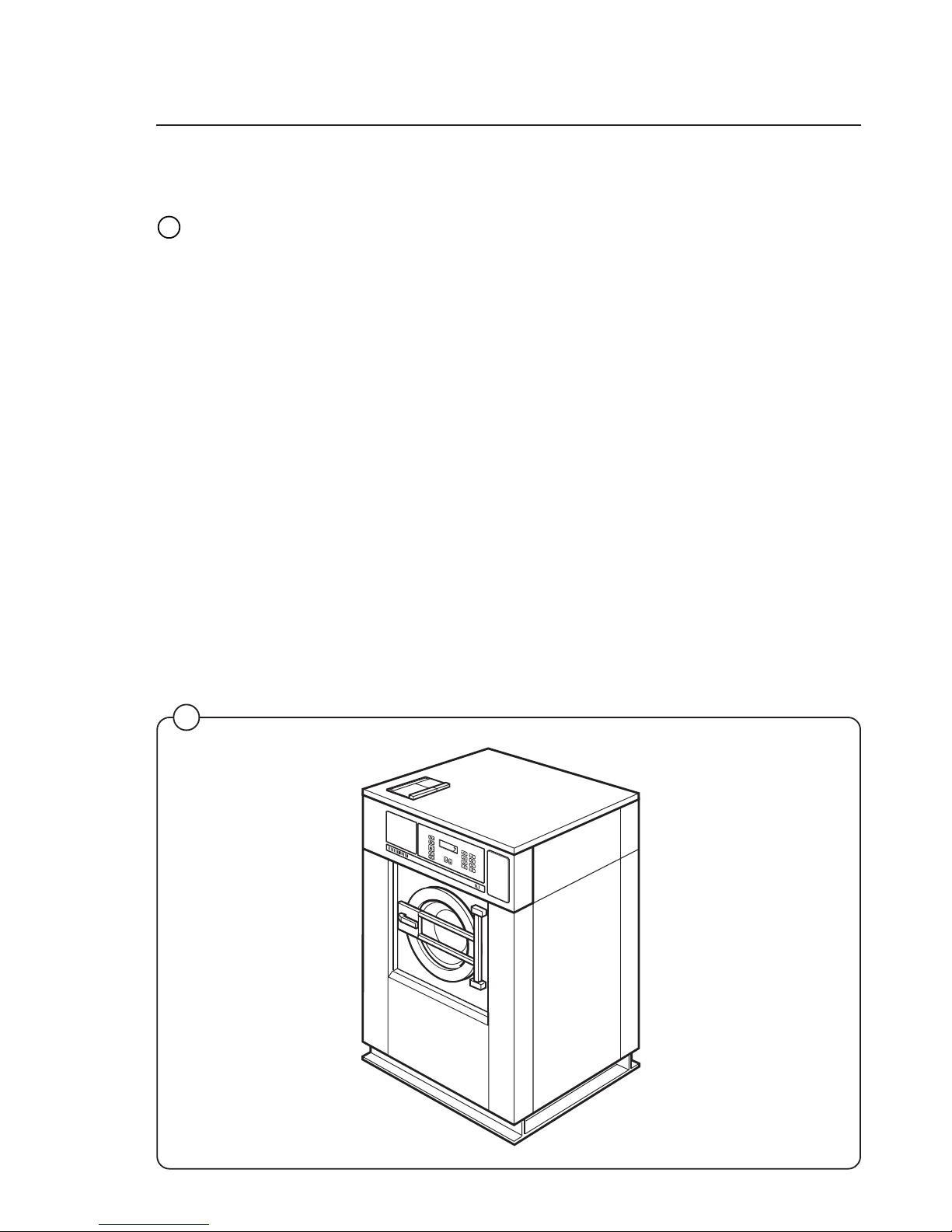
Introduction
The Selecta models washer/extractor has been developed to cover the heavy
duty requirements of hotels, motels, nursing homes, hospitals, professional
laundries, restaurants, airlines, steamships, schools, colleges and all on-premises laundries where flexibility and quick formula variation, coupled with high
quality automatic washing, are required.
The machines are free-swinging, i.e., the drum is moveable and spring suspended in relation to the frame. This minimizes vibrations transferred to the frame
thus simplifying installation, as no concrete base is required.
The high speed spin gives a G factor of approximately 300, providing very
efficient water removal during the spin.
All parts of the machine which come into contact with the items being washed
are made of heavy gauge surgical stainless steel, ensuring long life and lasting
beauty, as well as full protection for no-iron fabrics. All electrical components
are made accessible for servicing by simply removing the top panel.
This manual contains a technical description of the machine and instructions for
its installation, operation and maintenance. Together with the wiring diagram
which accompanies each individual machine it should be kept in a safe place
for easy reference.
When ordering spare parts or contacting Wascomat for any purpose always
give the machine serial number, model, voltage and other electrical characteristics appearing on the nameplate at the rear of the machine.
Fig.
1
60
40
60
95
60
40
30

8
Technical data
EX 30 S
Dry load capacity up to 30 lbs
Overall dimensions Width 870 mm 34 1/4'’
Depth 790 mm
Height 1325 mm
Net weight 290 kg 639 lbs
Floor load 3.3 ± 1.1 kN 790 ± 264 lbs force
Crated dimensions Volume 1.25 m
3
44 cu.ft
Weight 315 kg 695 lbs
Inner drum Diameter 620 mm 24 7/16'’
Depth 412 mm 16 5/16'’
Volume 120 litre 4.4 cu.ft
Speed of rotation Wash 24-48 r.p.m.
Distribution 78 r.p.m
Extraction up to 950 r.p.m.
G-factor During wash 0.8
During high extract 120-310
Voltage requirements 208-240 V 1-Phase 60 Hz
Rated power
Motor system 598 W
Extraction 1900 W
Overcurrent protection 1-Phase 15 A
Water connections
Water pressure, max 10 kp/cm
2
142 psi
Recommended water pressure 2-6 kp/cm
2
25-85 psi
Hose connection, water 20 mm 3/4'’
Hose connection, drain 75 mm 3'’

9
Technical data
EX 50 S
Dry load capacity up to 50 lbs
Overall dimensions Width 1000 mm 39 3/8'’
Depth 900 mm
Height 1435 mm
Net weight 553 kg 1218 lbs
Floor load 6.0 ± 2.0 kN 1440 ± 480 lbs force
Crated Dimensions Volume 2.05 m
3
72.3 cu.ft
Weight 588 kg 1295 lbs
Inner drum Diameter 750 mm 29 1/2'’
Depth 500 mm 19 11/16'’
Volume 220 litre 7.8 cu.ft
Speed of rotation Wash 44 r.p.m.
Distribution 70 r.p.m.
Extraction up to 850 r.p.m.
G-factor During wash 0.8
During High Extract 120-300
Voltage requirements Motor system 208-240 V 1-Phase 60 Hz
Rated power Wash 756 W
Motor, extraction 3000 W
Overcurrent protection 1-Phase 20 A
Water connections
Water pressure, max 10 kp/cm
2
142 psi
Recommended water pressure 2-6 kp/cm
2
25-85 psi
Hose connection, water 20 mm 3/4'’
Hose connection, drain 75 mm 3'’

10
Technical data
mm mm
A 870 1000
B 1325 1435
C 915 1100
D 790 900
E 125 200
F 630 615
G 570 550
H 470 600
J 1075 1170
K 200 230
L 170 170
M 110 110
N 1215 1325
O – 200
P 140 140
Q 1140 1235
R 175 175
S 305 370
T 1110 1220
U60 60
Outline and dimensions
4699
1. Opening for electrical cable connection
2. Steam connection (optional)
3. Cold water
4. Hot water
5. Hot water (only EX 50)
6. Drain outlet
7. Soap box
8. Liquid supply connections
EX 50 S
EX 30 S
6
5
G
F
B
E
C
D
T
U
4
1
2
S
R
J
Q
N
7
3
H
K
O
L
P
M
A
11
Installation
2
3
4
1247 B
1248 B
1249 B
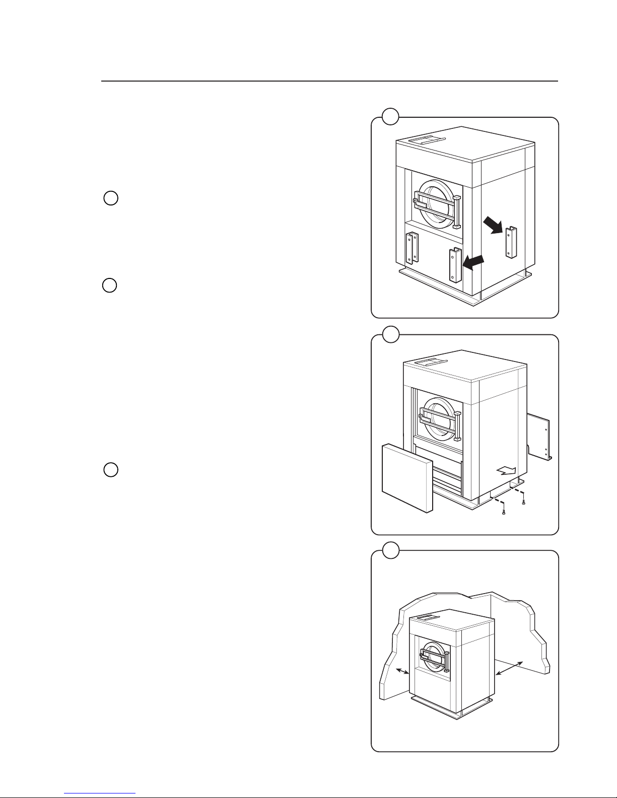
Installation
The machine is delivered with expansion bolts
and other items packed inside the drum.
Shipping securities
The machine is shipped with four large metal
brackets bolted to the four suspension legs as
well as a support between the pulley and the
back plate.
Prior to installation, follow these steps:
• Unpack the machine.
• Remove the lower front panel and the two rear
panels.
• Remove the support from the pulley at the
back of the machine.
• Remove both front brackets.
• Remove both rear brackets.
Placement
The machine should be installed close to a floor
drain or open drain to make installation, use and
service easier.
The following clearances are recommended for
ease of installation and service:
• At least 20 inches between the machine and
the wall behind it.
• At least 2 inches on each side.
The floor must be able to support a static load of
790 lbs for the EX-30 and 1440 lbs for the EX-50.
The maximum impact load at extraction is 260
lbs force for the EX-30 and 480 lbs for the EX-50.
Fig.
2
Fig.
3
Fig.
4
300 mm
1000 mm
12
Installation
5
6
7
0620
0621
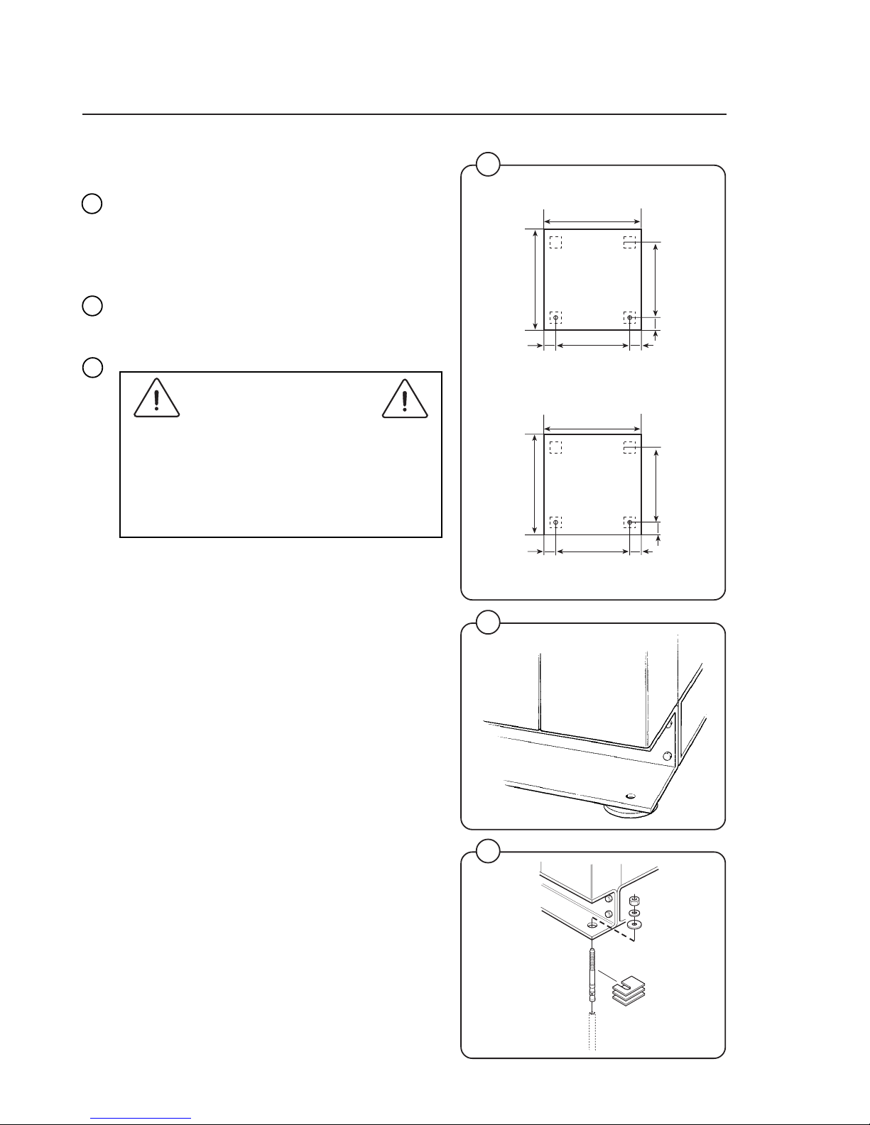
Mechanical installation
• Mark and drill two holes 3/8'' in (8 mm) in
diameter and approximately 3 1/2'' in. (90 mm)
deep according to the dimensions in figure 5.
• Place the machine in position. Never lift the
machine by the door or handle.
• Check that the machine is level and steady.
Use stainless or galvanized washers between
the machine and the floor.
• Insert the expansion bolts supplied with the
machine. Fit the washers and nuts.
It is of utmost importance that the machine
is level, from side-to-side as well as frontto-rear. If the machine is not properly
levelled, it may result in out-of-balance
cutout without a real out-of-balance in the
drum.
Fig.
5
Fig.
7
Fig.
6
4811
870
780
33
4343
790
716
=
=
Front
Front
=
=
1000
910
33
4343
900
830
EX 30 S
EX 50 S
13
Installation
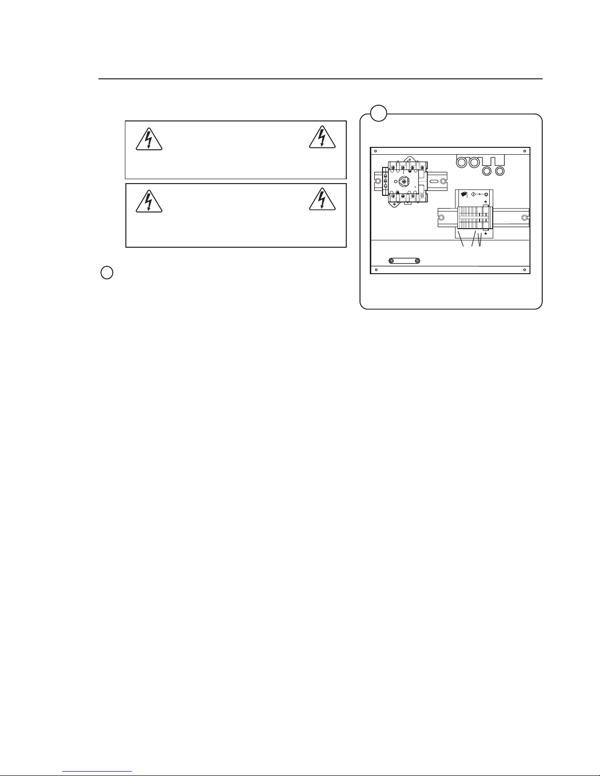
Connection for liquid supply (option)
Electrical installation must be carried out
by an authorized personnel!
Installed appliances must be EMC approved
according to EN 50081-1 and EN 50082-2.
The connections A (1-5) are signals for the liquid
supply pumps.
The connections B are for Neutral (1) and Phase
(2).
8
4722
Fig.
8
T1
T2
T3L1N
N
L2
L3
X146-1
471 75 98 01
12
3
4
125
12
3
4
125
A B
14
Installation
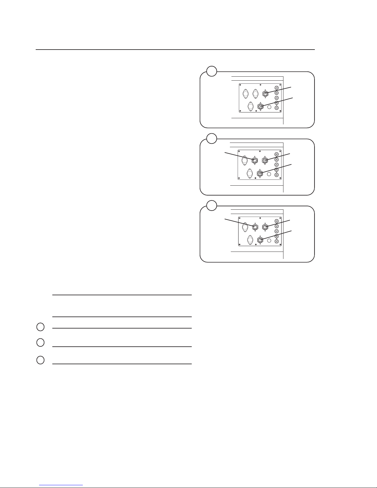
Water connections
All intake connections to the machine are to be
fitted with manual shut-off valves and filters, to
facilitate installation and servicing. In certain
cases non-return valves will need to be fitted
before the machine to comply with local plumbing
regulations.
Water pipes and hoses should be flushed clean
before installation. After installation hoses should
hang in gentle arcs.
The machine may have between two and four
DN 20 (R 3/4") water connectors. All connectors
present on the machine must be connected up.
The table shows the possible connection options,
which will depend on the water types to be
connected to the machine. Check the machine
plates too.
All water connectors must be connected up,
otherwise the wash program will not function
correctly.
Hoses are to be of an approved type and grade,
to comply with national regulations.
The water pressure data is as follows:
• min: 40 kPa (0,4 kp/cm
2
)
• max: 1 MPa (10 kp/cm
2
)
• recommended: 200-600 kPa (2-6 kp/cm
2
)
Water type Water connection
12 3 4
cold and hot cold hot
cold, hot and
cold/hard cold hot cold/hard
cold and hot cold hot cold or
hot
Fig.
9
Fig.
10
Fig.
11
9
10
11
4702
4703
4705
Hot
Cold
EX 30 S
Cold
EX 30 S
Hot
Cold
EX 50 S
Hot
Cold
Hot/
Cold

15
Installation
Drain connection
Connect a 3'’ (75 mm) flexible hose to the drain
outlet of the machine.
The drain must not have any sharp bends and
must slope downward from the machine to
assure proper drainage. The outlet must open
freely to the main drain.
Do not reduce the size of the drain connection
from the machine to the waste line.
12
1258
Fig.
12
16
Installation
13
1719
STEAM HOSE APPROVED FOR
min. 0,1 MPa
max. 0,8 MPa
CABLE FROM MACHINE
SEAL WITH TEFLON
OR SIMILAR
CONNECTION STEAM
INJECTOR IN MACHINE
For rebuilding look at the wiring diagram of the machine.
17
Installation
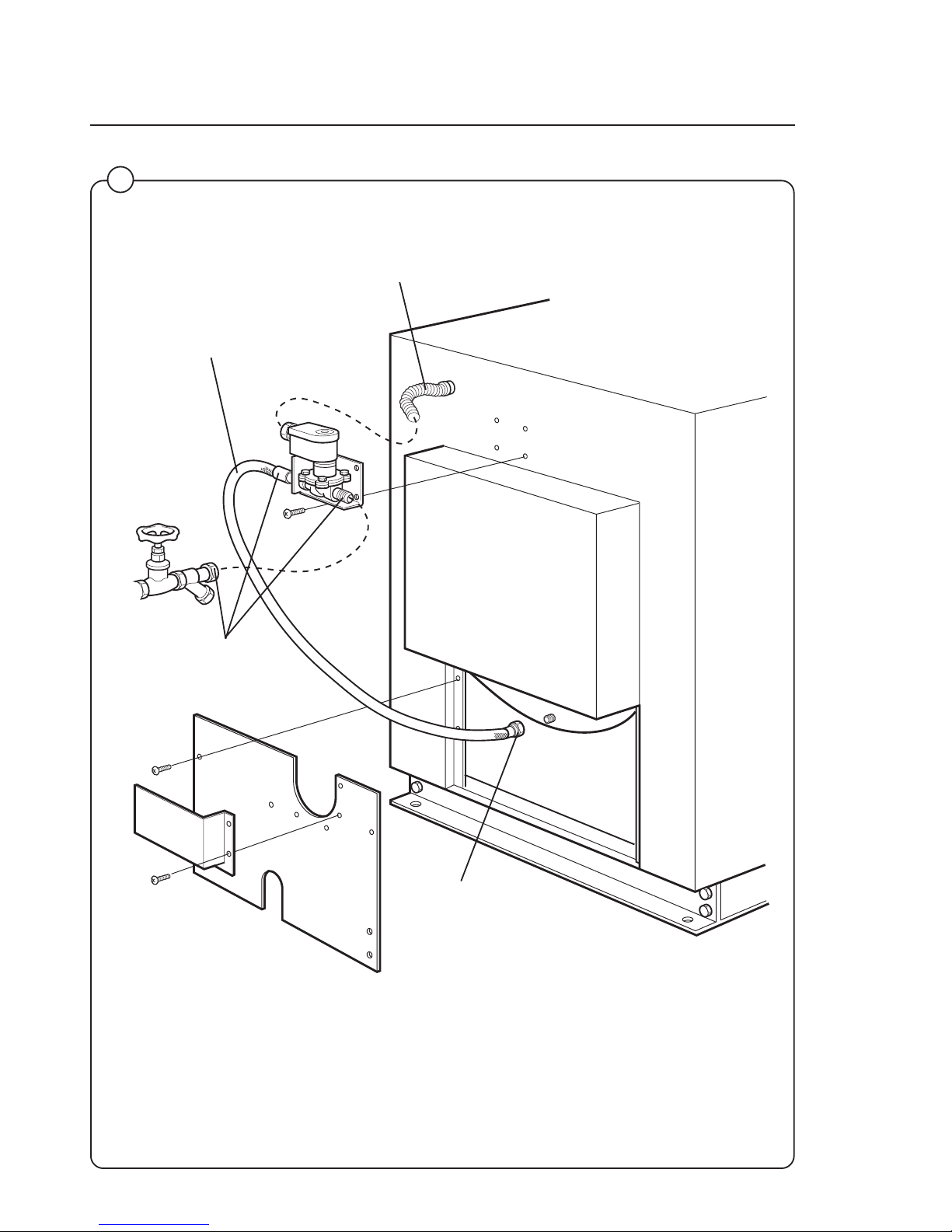
Steam connections (optional steam heating)
Steam pressure required:
• minimum 7 PSI
• maximum: 110 PSI
• recommended: 40-85 PSI
A steam valve for this machine type is fitted
separately in a bracket on the upper rear cover
plate. The steam valve, hose and filter are supplied with the machine.
Steam-flush all pipes and hoses before connection.
Installation instructions:
• Install rear cover plates.
• Install steam valve bracket and valve. The
steam valve must be mounted in upright
position.
• Connect the steam hose between the steam
valve and the steam intake on the machine.
• The steam inlet pipe must be fitted with a
manual cut-off valve. Fit the filter supplied with
the machine to the manual cut-off valve.
• Connect an approved 1/2'' steam hose between the steam valve and the filter. The
connection must be vertical or be fitted with a
pipe connector in order to avoid sharp angles
in the hose.
• Connection size at filter: DN15 (R 1/2''').
Check that there are no sharp angles or
bends in the connection hose.
14
1254
Fig.
14
18
Installation
15
Fig.
15
4724 B
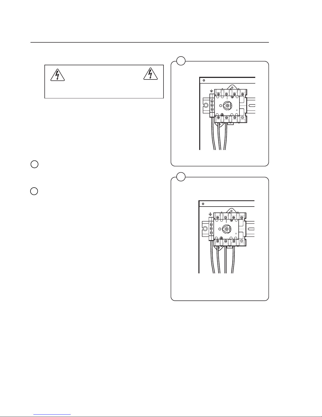
Electrical installation
Electrical installation must be carried out
by an authorized personnel!
Mount a multi-pole switch prior to the machine to
facilitate installation and service operations.
The connecting cable should hang in a gentle
curve.
Fuse size can be found on next page.
Single-phase connection:
Connect the earth and other two wires as shown
in example "1AC" in the figure.
Three-phase connection:
Connect the earth, neutral and phase wires as
shown in example "3AC" in the figure.
When the installation is completed, check:
• that the drum is empty,
• that the machine operates by turning on the
mains switch, starting the machine and using
RAPID ADVANCE to reach the spin cycle
(see operations manual).
16
4726
Fig.
16
T1
T2
T3L1N
N
L2
L3
T1
T2
T3L1N
N
L2
L3
1AC
3AC

19
Installation
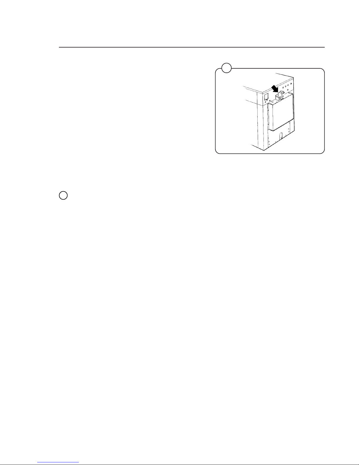
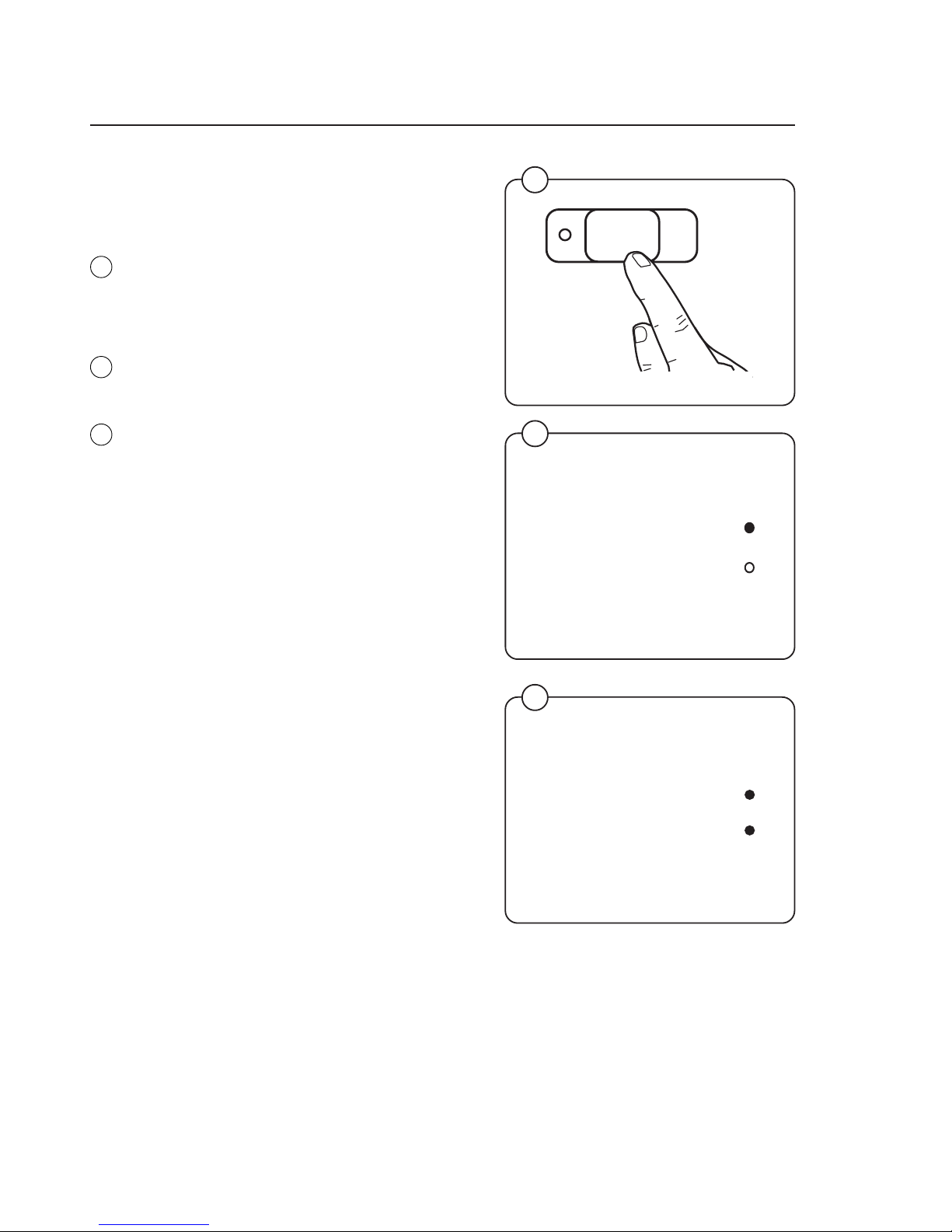
Setting the timing on the electrolube oil dispenser
This machine is equipped with an electronic oiler
which lubricate the seals on a timed bases. With
the rear panel removed locate the oiler, which is
attached to the base frame at the lower rear.
Pry off the switch panel cap with a screwdriver.
• Under the cap are the switches for time setting.
• The light will start flashing after a few minutes
and will continue to flash every 15th to 20th
seconds as long as the dispencer is in operation.
• The decal shown below should be affixed at
the front of the machine and updated as
required.
Fig.
19
2207
19
18
17
2208 A
Date Last Replaced Date Last Replaced
IMPORTANT
NOTICE
This machine is equipped with an automatic oiler,
located at the right rear of the machine, which keeps
it lubricated for long bearing and seal life.
The amount of oil in the container is sufficient for
approximately one year's lubrication. It is of utmost
importance that the oiler does not become empty.
Therefore we recommend that the rear panel be
removed and a visual inspection made on a
bimonthly basis. When the oil reaches a low level,
the cannister must be replaced with a new one
available from Wascomat as Part No. 827601.
Fig.
17
Fig.
18

20
4944
Start-up and safety checklist
Before initial start-up of an EX 30 S/EX 50 S
washer, the following safety checks must be
performed:
• Make sure that all electrical and plumbing
connections have been made in accordance
with applicable local codes.
• Use only flexible water fill and drain hoses of
the proper length to avoid sags and kinks.
• Make sure the machine is properly grounded
(electrically).
Before the machine is operated, the door safety
interlock must be checked for proper operation
as follows:
• When washer loading door is open, the
machine must not start. Verify this by attempting to start washer with door open.
• When washer is in operation, the loading door
is locked and cannot be opened. Verify this by
attempting to open the loading door when the
machine is operating. If necessary, consult
this manual for proper operation of the door
safety interlock or call a qualified serviceman.
If the machine starts with the door open or
the door can be opened after machine is
running, the machine must immediately be
placed OUT OF ORDER and the door
interlock system must be repaired or
replaced. Disconnect electrical power from
the machine until the necessay repairs are
made.
Door safety interlock must be checked
daily in accordance with above procedure.
Before servicing Wascomat equipment,
disconnect electrical power.
Fig.
20
Fig.
21
20
Installation
21
4945
123
45
6
7
89
0
123
45
6
7
89
0

21
• This machine is designed for water washing only.
• Machines must not be used by children.
• All installation operations are to be carried out by qualified personnel.
Licensed personnel are necessary for all electric power wiring.
• The interlock of the door must be checked daily for proper operation
and must not be bypassed.
• All seepage in the system, due to faulty gaskets etc., must be repaired
immediately.
• All service personnel must be fully familiar with the operating manual
before attempting any repair or maintenance of the machine.
• This machine must not be sprayed with water, otherwise short
circuiting may occur.
• Fabric softeners with volatile or inflammable fluids are not to be used in
this machine.
Safety rules
Safety rules

22
1
Supply
signals
A
B
2
3
4
5
START
STOP
6
1
Program
step
7
Final extract
Doorlock delay
Door unlocked
2
3
4
5
Prewash
Mainwash
Rinse
Operating instructions
Operating instructions
The Emerald Series program unit controls the various functions of the machine
in a certain time sequence with the aid of seven built-in standard programs.
The standard programs can also be modified by selecting various options. By
selecting options, the user has access to programs for all types of wash loads
and degrees of soiling.
The control panel consists of program selection buttons (A) and (B), a
combined start, pause and rapid advance button (C), symbols with LEDs (D)
which show the program selected and the program sequence, plus an alphanumeric display (E).
The alphanumeric display shows illuminated green characters.
In the event of faults, error codes will be displayed on this window. See Fault
codes.
22
Explanation of control panel
A Program selection buttons
B Option buttons
C Start/pause and rapid advance button
D Symbols with LEDs to indicate program sequence
E Information display
4996
Fig.
22
D
E
B
A
C

23
Operating instructions
Washing
• Press the button for the desired program.
• Now the LEDs alongside the program symbols will show what the selected program
consists of.
• Press the button(s) for any options required.
Gentle actions consists of 6 seconds
rotation, as opposed to 18 seconds pause
and 6 seconds pause and 14 seconds
rotation for Normal action.
• Press the START button.
3426
4995
3435
24
Fig.
23
Fig.
24
Fig.
26
27
Fig.
25
Perm Press
Quick-Wash
2
3
4
5
START
Hot
Warm
Cold
Delicate
Heavy Soil
6
1
7
START
Fig.
27
A
B
25
26
23
1
Supply
signals
Program
step
Final extract
Doorlock delay
Door unlocked
2
3
4
5
Prewash
Mainwash
Rinse

24
• Now the display will show the clock symbol
and two digits. The two digits are the time left
before the wash will be finished.
The two digits indicating time left will not
appear when the machine is first installed.
Each program needs to have been used at
least once before the time left will be displayed.
• For 5 minutes immediately after START is
pressed the colon character (
: ) will flash on
the display. As long as this character is still
flashing a new program can be selected
(without the drain opening). This means you
still have the chance to change the setting if
the wrong program has been selected. Do as
follows:
• Press START.
• Select a new program.
• Press START again after making any change
in the program selected.
If for any reason you wish to halt the wash cycle
for a time, press the START button for a moment
or two. The program will be suspended and the
drain will remain closed.
To restart the program, press the START button
again briefly.
Fig.
28
Operating Instructions
Fig.
29
Fig.
30
30
3435
START
4091
29
3141
28
1

25
START
Operating Instructions
For coin-operated machines
Select a wash program, then insert the number
of coins corresponding to the figure shown on
the display.
As each coin is added the machine counts
backwards towards 00 on the display. The
machine will not start until the display shows 00.
• Press the START button.
• Now the display will show the clock symbol
and two digits. The two digits are the time left
before the wash will be finished.
The two digits indicating time left will not
appear when the machine is first installed.
Each program needs to have been used at
least once before the time left will be displayed.
• For a time immediately after START is pressed the colon character (
: ) will flash on the
display. As long as this character is still
flashing a new program can be selected
(without losing anything). This means you still
have the chance to change the setting if the
wrong program has been selected.
• Press PAUSE/START.
• Select a new program.
• If the new program costs more to run than
the amount already paid, the difference will
be shown on the display. Insert enough coins
to make the display show 00 again.
• Press START again after making any change
in the program selected.
3435
2253
Fig.
31
3141
31
32
33
Fig.
32
Fig.
33
26
Doorlock delay
Door unlocked
Rapid advance
Whole steps in programs can be skipped using
rapid advance.
• Press and hold the START button until the
program indicator LEDs have moved past the
program steps you wish to skip.
Program end
After final extraction, the LED by the "doorlock
delay" comes on. This shows that the door lock
will shortly be unlocked.
The door will not actually be unlocked until the
green LED by the "door unlocked" comes on,
accompanied by an audible signal. This takes
about 1 minute.
Troubleshooting
If the machine won’t start, check that:
• the circuit breaker is on.
• the manual shut-off valves for water are open.
• a program has been selected.
• the door is properly locked.
3435
Fig.
34
3424
3425
Fig.
36
Operating Instructions
34
35
36
Fig.
35
START
Doorlock delay
Door unlocked

27
A
1
1
4
3
2
6
5
8
7
9
Programming
Coin-operated machines
In coin-operated machines the prices for the
various programs have to be programmed in.
Values from the coin mechanism (the
accumulated value) can be read out with the aid
of the service program.
If a machine is fitted with a coin mechanism after
its original installation the relevant electronic
circuitry will have to be activated before the prices
can be programmed in.
Only trained service personnel may use the
service program and program in prices for
coin operation.
Activation of electronic circuitry in machines fitted with coin operation after original
installation.
• Press the service button.
Now certain of the buttons switch to being
number keys (1 to 9), with the START button
being 0.
3429
Fig.
37
Fig.
38
38
3400
37
 Loading...