


Operating Manual
MODEL NO. WHLFP715M
WASHER INSTALLATION MANUAL
DOC. NO. 0020506871B
EDITION 21.2017

ATTENTION INSTALLER
Four transportation bolts are installed in the rear of the machine,
to protect the suspension and tub assembly from damage during
shipment. REMOVE ALL FOUR BOLTS AND PLASTIC TUBES
THROUGH WHICH THE BOLTS PASS BEFORE OPERATING THE
MACHINE!! See instructions later in this manual.
Installation Manual
WHLFP715M
WARNING: ALL OPERATING AND MAINTENANCE PROCEDURES SHOWN IN THIS MANUAL
MUST BE FOLLOWED AT THE FREQUENCY SPECIFIED FOR PROPER OPERATION OF
YOUR MACHINE.
PLEASE ENTER THE FOLLOWING INFORMATION AS IT APPEARS ON THE MACHINE(S)
DATA PLATE(S).
MACHINE MODEL
MACHINE SERIAL NUMBER(S)
ELECTRICAL CHARACTERISTICS: VOLTS, PHASE, HZ.
KEEP THIS MANUAL IN A SECURE PLACE FOR FUTURE REFERENCE.
244824

Intentionally blank

IMPORTANT SAFETY INSTRUCTIONS
IMPORTANTES MESURES DE SECURITE
WARNING -
To reduce the risk of re, electric chock, or injury to persons when using your appliance:
AVERTISSEMENT -
Pour réduire les risques d´incendie, de choc électrique ou de blessure quand, I´appareil est utilisé:
1. Read all instructions before using the appliance.
Lire toutes les instructions avant d’utiliser l’appareil.
2. This machine must be installed according to the installation instructions.
Ce machine doit être visseé sur le plancher selon les instructions d’installation.
3. This machine MUST be serviced and operated in compliance with manufacturers instructions. CHECK DOOR LOCKS
EVERY DAY FOR PROPER OPERATION TO PREVENT INJURY OR DAMAGE. IF THE DOOR LOCK FAILS TO
OPERATE PROPERLY, PLACE THE MACHINE OUT OF ORDER UNTIL THE PROBLEM IS CORRECTED.
IL FAUT QUE cette appareil soit entretenue et actionnée conformement aux instructions du fabriquant. CONTROLEZ LA
SERRURE DE PORTE TOUS LES JOURS AFIN DE EVITER DES DOMMAGES OU DES RISQUES PERSONNELLES.
SI LA SERRURE DE PORTE NE FONCTIONNE PAS, IL FAUT METTRE LA MACHINE HORS SERVICE JUSQU’Á LE
PROBLEME SOIT CORRIGÉ.
4. Do not wash articles that have been previously cleaned in, washed in, soaked in, or spotted with gasoline, drycleaning
solvents, or other ammable or explosive substances, as they give off vapors that could ignite or explode.
Ne pas laver des articles qui ont été nettoyés ou lavés avec de l’essence, des solvants pour nettoyage à sec ou d’autres
substances inammables ou explosives, ou que l’on a fait tremper dans ces produits. Ces substances dégagent des
vapeurs qui peuvent s’enammer ou exploser.
5. Do not add gasoline, dry-cleaning solvents, or other ammable or explosive substances to the wash water. These
substances giveoff vapours that could ignite or explode.
Ne pas ajouter d’essence, de solvants pour nettoyage à sec ou d’autres substances inammables ou explosives à l’eau
de lavage. Ces substances dégagent des vapeurs qui peuvent s’enammer ou exploser.
6. Under certain conditions, hydrogen gas may be produced in a hot-water system that has not been used for 2 weeks or
more. HYDROGEN GAS IS EXPLOSIVE. If the hot-water system has not been used for such a period, before using a
washing machine, turn on all hot-water faucets and let the water ow from each for several minutes. This will release any
accumulated hydrogen gas. As the gas is ammable, do not smoke or use an open ame during this time.
De l’hydrogène peut être produit dans un système à eau chaude qui n’a pas été utilisé depuis deux semaines ou plus.
L’HYDROGÈNE EST EXPLOSIF. Si le système à eau chaude n’a pas été utilisé depuis un certain temps, ouvrir tous les
robinets d’eau chaude et laisser l’eau couler pendant plusieurs minutes avant d’utiliser une laveuse, l’hydrogène accu
mulé, le cas échéant, s’échappera. L’hydrogène étant inammable, ne pas fumer ou utiliser un appareil à amme nue
pendant que l’eau coule.
7. Do not allow children to play on or in the appliance. Close supervision of children is necessary when the appliance is
used near children.
Ne pas permettre aux enfants de jouer sur ou dans l’appareil. Surveiller ètriotement les enfants lorsqu’ils se trou veent
près d l’appareil qui fonctionne.
8. If the machine is to be discarded, remove the door to prevent accidental entrapment.
Avant de mettre l’appareil hors service ou de jeter, retirer la porte.
9. Do not reach into the appliance if the tub is moving.
Ne pas mettre la main dans l’appareil lorsque la cuve bougent.
10. Do not install or store this appliance where it will be exposed to the weather.
Ne pas installer ou placer cet appareil dans un endroit où il sera exposé aux intempéries.
11. Do not tamper with controls.
Ne pas traquer les commandes.
12. Do not repair or replace any part of the appliance or attempt any servicing unless specically recommended in the user
maintenance instructions or in published user-repair instructions that you understand and have the skills to carry out.
Ne pas réparer ou remplacer les pièces de l’appareil ou procéder à l’entretien de celui-ci sauf si les instructions visant
l’entretien et les réparations qui doivent être effectués par l’utilisateur le spécient, si vous comprenez bien ces instructi
si vous possédez les connaissances nécessaires.
MANUFACTURED BY HAIER EXCLUSIVELY FOR LAUNDRYLUX

NOTICE TO: OWNERS, OPERATORS AND DEALERS
IMPROPER INSTALLATION AND INADEQUATE MAINTENANCE, POOR HOUSEKEEPING AND WILLFUL NEGLECT OR
BYPASSING OF SAFETY DEVICES MAY RESULT IN SERIOUS ACCIDENTS OR INJURY. TO ASSURE THE SAFETY
OF CUSTOMERS AND/OR OPERATORS OF YOUR MACHINE, THE FOLLOWING MAINTENANCE CHECKS MUST BE
PERFORMED ON A D A I LY BASIS.
NOTICE À L’ATTENTION DES PROPRIÉTAIRES, UTILISATEURS ET REVENDEURS
UNE INSTALLATION INCORRECTE ET UN ENTRETIEN INADÉQUAT, DE MÊME QUE LA NÉGLIGENCE OU LA
NEUTRALISATION DÉLIBÉRÉES DES DISPOSITIFS DE SÉCURITÉ, PEUVENT ÊTRE CAUSES DE BLESSURES OU
D’ACCIDENTS SÉRIEUX. POUR ASSURER LA SÉCURITÉ DES CLIENTS ET/OU DES UTILISATEURS DE VOTRE
MACHINE, IL EST INDISPENSABLE DE PROCÉDER CHAQUE JOUR AUX CONTRÔLES DE ROUTINE CI-APRÈS.
1. Prior to operation of the machine, check to make certain that all operating instructions and warning signs
are afxed to the machine and legible. (See the following page of this manual for description and location
of the signs.) Missing or illegible ones must be replaced immediately. Be sure you have spare signs and
labels available at all times. These can be obtained from your distributor or from Laundrylux.
2. Check the door safety interlock, as follows:
(a) OPEN THE DOOR of the machine and attempt to start in the normal manner:
For coin-operated models, insert the proper coins to start the machine.
For card-operated models, insert the card to start the machine.
THE MACHINE MUST NOT START
(b) CLOSE THE DOOR to start machine operation and, while it is operating, attempt to
open the door without exerting extreme force on the door handle. The door should
remain locked!
If the machine can start with the door open, or can continue to operate with the door
unlocked, the door interlock is no longer operating properly. The machine must be
placed out of order and the interlock immediately replaced.
3. DO NOT UNDER ANY CIRCUMSTANCES ATTEMPT TO BYPASS OR REWIRE ANY OF THE MACHINE
SAFETY DEVICES AS THIS CAN RESULT IN SERIOUS ACCIDENTS.
4. Be sure to keep the machine(s) in proper working order. Follow all maintenance and safety procedures.
Further information regarding machine safety, service and parts can be obtained from your dealer or from
Laundrylux through its Technical Support Hotline - (516) 371-0700.
All requests for assistance must include the model, serial number and electrical characteristics as
they appear on the machine identication plate. Insert this information in the space provided on the
previous page of this manual.
5. WARNING: DO NOT OPERATE MACHINE(S) WITH SAFETY DEVICES BYPASSED, REWIRED OR
INOPERATIVE! DO NOT OPEN MACHINE DOOR UNTIL DRUM HAS STOPPED ROTATING!
AVERTISSEMENT: NE PAS FAIRE FONCTIONNER LA (LES) MACHINE(S) AVEC UN DISPOSITIF
DE SÉCURITÉ NEUTRALISÉ, RECÂBLÉ OU NON OPÉRATIONNEL! NE PAS OUVRIR LA
MACHINE TANT QUE LE TAMBOUR NE S’EST PAS IMMOBILISÉ!

NOTICE TO INSTALLER
Improper installation of this machine:
• May cause serious damage to the machine.
• May result in other property damage.
• May cause personal injury.
• Will void the manufacturer’s warranty.
Location Requirements
• The location for your washer should have a at and even oor. This will improve
performance, minimize noise and decrease washer movement.
• The unit can be installed in a laundry room, or other recessed area.
Additional Requirements
• A grounded electrical outlet. Do not use an extension cord with this appliance. It must be
plugged directly into a grounded electrical outlet.
• It is not recommended to use washer on soft ooring such as carpets or foam.
• Do not operate washer if ambient room temperature is less than freezing, as this can cause
damage to the unit.

Contents
Technical Data .................................................................................................. 1:1
Installation ........................................................................................................2:1
Water Connections .....................................................................................3:1
Drain Connection ........................................................................................ 4:1
Connection of External Liquid Supplies ...................................................... 5:1
Function Checks ...............................................................................................6:1
Preventive Maintenance ...................................................................................7:1
The manufacturer reserves the right to make changes to design, material
and/or specications without notice.
Safety Instructions
• The machine is designed for water washing only.
• The machine must not be used by children.
• Allinstallationoperationsaretobecarriedoutbyqualiedpersonnel.
Licensed personnel are necessary for all electric power wiring and
plumbing.
• The door interlock must be checked daily for proper operation and
must not be bypassed.
• All leaks, due to faulty gaskets etc., must be repaired immediately.
• All service personnel must be fully familiar with the operating manual
before attempting any repair or maintenance of the machine.
• The machine must not be sprayed with water.
• Donotaddammableorexplosivesubstancestothewashwater.
Theycangiveoffvaporsthatcouldigniteorexplode.
Consignes de sécurité
• Lamachineestconçuepourlelavageàl’eauexclusivement.
• La machine ne peut être utilisée par des enfants.
• Touslestravauxd’installationdoiventêtreeffectuésparunepersonne
qualiée.Touslescâblagesélectriquesdoiventêtreréalisésparun
électricien diplômé.
• Leverrouillageduhublotdoitêtrevériéchaquejouretnepeutêtre
neutralisé.
• Toutefuitedusystème,dueàdesjointsdéfectueuxetc.,doitêtre
réparée sans délai.
• Tous les membres du personnel d’entretien doivent être parfaitement
familiarisés avec le manuel d’entretien avant d’entreprendre une
réparation ou un entretien de la machine.
• Nejamaisaspergerd’eaulamachinesouspeinederisquerun
court-circuit.
• Nepasutiliserdanslamachinedesadoucissantstextilescontenant
desliquidesvolatilsouinammables.
Technical Data
Technical Data
WHLFP715M
1:1
Innerdrum
volume litres/ft
diameter mm/inch
Drum speed
wash rpm
extraction max rpm
G-factor
Weight, net kg/lbs
Connections WHLFP715M
Water valves
connection
3
3/4" Garden Hose via included hoses
98/3.5
554/21 13/16
45
1000
306
136/300
DN20
Rec. water pressure psi
kPa
Functioning limits psi
for water valve kPa
Capacity at 45 psi
(300 kPa) gallon/min
liter/min
Drain hose inch
outer Ø mm
Draining gallon/min
capacity liter/min
30-90
200-600
8-145
50-1000
2.6
10
1
25
5
20
1:2
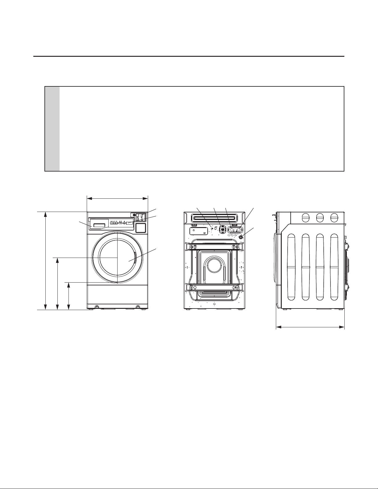
1
Power Line
2
Air Vent for Safety
3
Cold Water
4
Hot Water
5
Drain
6
Coin Meter (coin operated models only)
7
Control Panel
8
Detergent Dispenser
9
Door
D
8
Technical Data
2
6
7
1
3
4
5
A
B
NOTES:
9
C
E
A 1098mm = 43 1/4 inch
B 584mm = 23 inch
C 310mm = 12 3/16 inch
D 686mm = 27 inch
E 765mm = 30 1/8 inch
Installation
Installation
For safety, two people should install this product.
Leave the machine on the transport pallet until it can be placed in the nal, prepared position.
First remove all the packing materials. Upon opening of the package, water drops may be
seen on the plastic bag and the drum. This is a normal phenomenon resulting from water tests
in the factory.
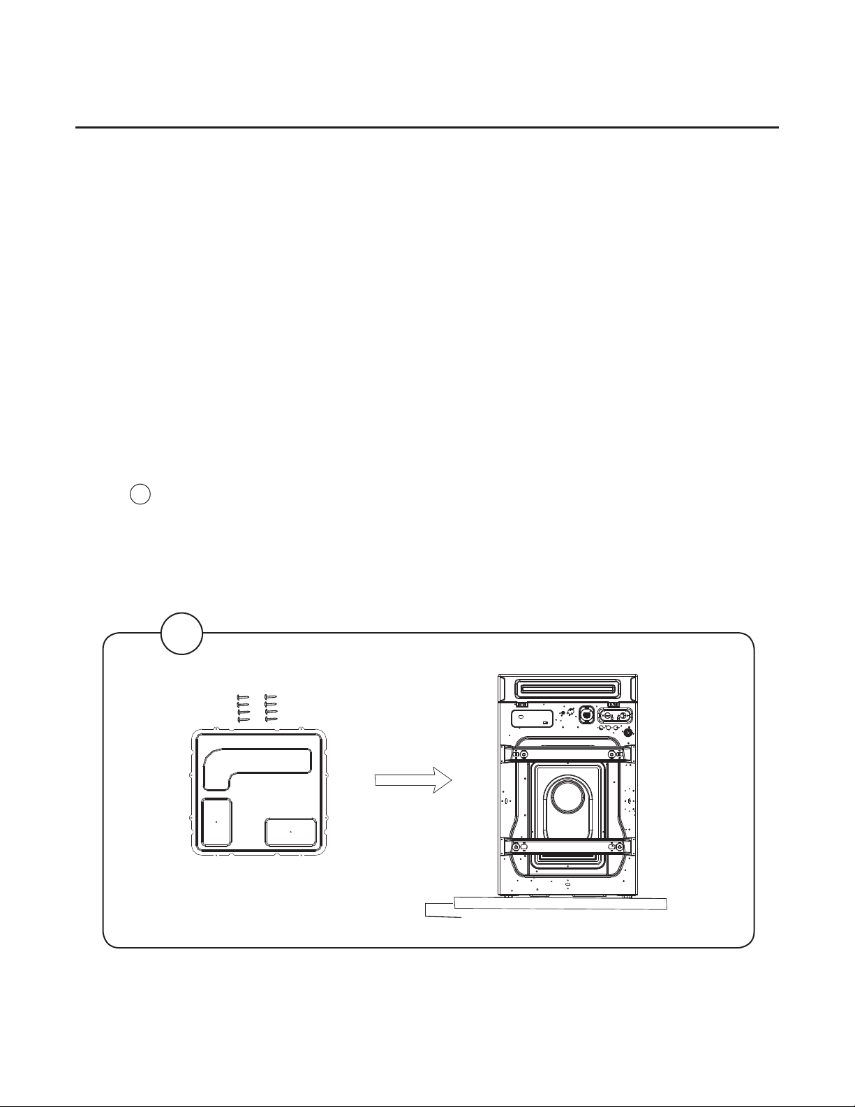
NOTE: 1. A bottom cover plate is wrapped in the top of the packing material.
2. Be careful while handling the bottom cover.
3. Remove all anti-scratch lm from the washer.
Install the bottom cover plate
1. Lay the package carton on the ground.
Fig.
1
2. Lay the washer slowly down on its back on the package carton.
2:1
3. Install the bottom cover on the bottom of the machine using the 8 screws provided
in the accessories bag.
4. Lift the washer to the upright position.
1
Back Side
Package Carton
2:2
Transportation Bolts
The washer is tted with transportation bolts to prevent internal damage during transportation.
Transportation bolts must be removed before using the washer.
Installation
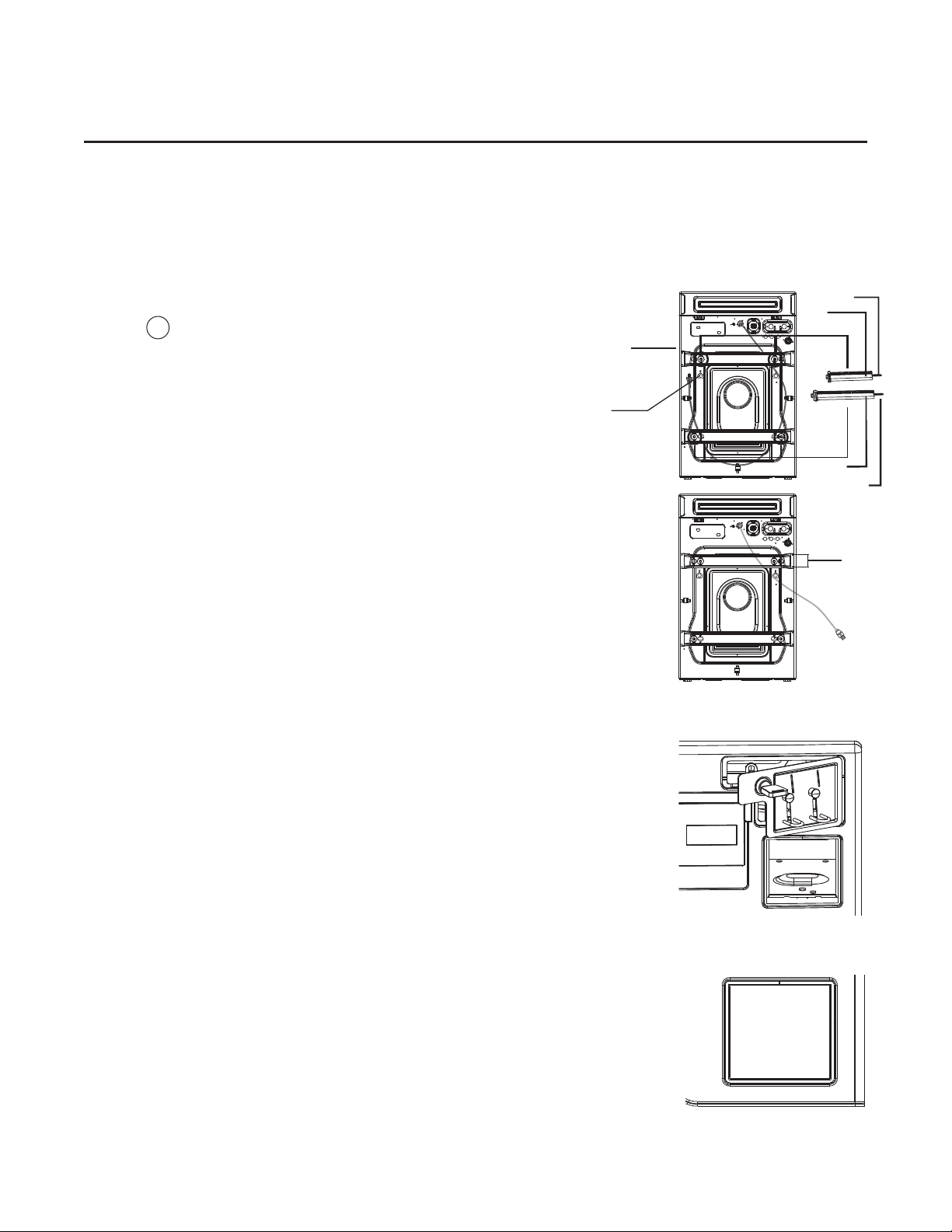
Removing Transportation Bolts
Fig.
1. Unscrew the 4 bolts with a wrench. Remove the
lower 2 bolts rst, then the upper two. One of the
2
bolts retains the power cord of the washer to
prevent operating without removing bolts.
2. Remove the bolts and the red plastic sleeves to
release the power cord. Keep the 4 bolts and
sleeves for future use.
NOTE: If transportation bolts and sleeves are not removed, it
may cause severe vibration, noise and malfunction,
as well as damage to the machine.
NOTE: When the washer is transported the transportation
bolts and the sleeves must be reinstalled.
3. Close the 4 holes with the caps supplied.
Install the Coin Meter (coin operated models)
1. Unlock coin meter lock plate with the provided key.
2. Partially open the lock plate and slide to the left to
remove it from the console.
3. Install the coin meter faceplate into the lock plate and
then assemble the coin meter(s) into the faceplate.
Brace
Cap
Fig. 2
Fig. 3
Bolt
Sleeve
Sleeve
Bolt
Screws
4. Plug the coin meter(s) into COIN 1 (Red) and COIN 2
(White) harnesses inside the washer.
5. Carefully reattach the coin meter harnesses using the
reclosable cable ties mounted on the chassis behind the
coin meter(s). Make sure the harnesses do not obstruct
coins dropping into the coin vault and that they do not
touch moving parts on the sides of the coin meter(s).
(These measure the size and weight of coins, and must
be free of interference.)
6. Reinstall the coin meter lock plate by aligning the right
tab behind the console, sliding it to the right, then closing
and locking it. See Fig. 3
Install the Blocking Piate (non metered models)
1. Push the blocking plate into the coin vault until the tabs
lock in place. See Fig. 4
Fig. 4
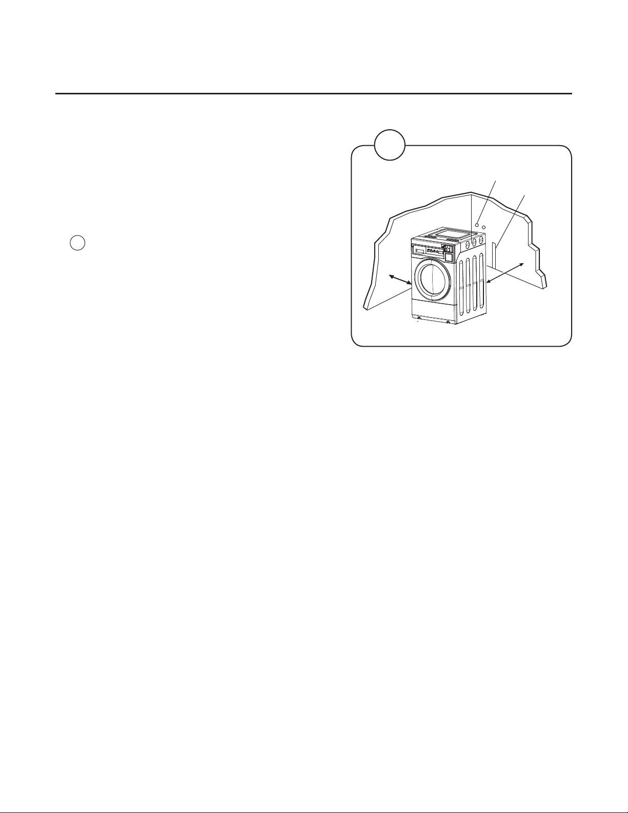
Siting
Installation
2:3
Install the machine close to a drain standpipe or
oor drain, and within 4 feet of the water supply
spigots. In order to make installation and servicing
the machine easier the following clearances are
recommended:
• At least 20 inches (500 mm) between the
Fig.
4
machine and the wall behind.
• Minimum 1 inch (25 mm) to next machine if
more than one machine is installed in a row.
Floor
• The oor must be smooth and hard. Do not
install the machine on carpet or other soft
material.
• The oor must hold the total weight of the
machine lled with water and a load. This
static weight is 416 pounds (188 kilograms).
• Adjust the leveling legs of the machine, as
needed, to ensure that it is level front to back,
and side to side, and so that all four feet are
in contact with the oor. After leveling the
machine, use the enclosed locknut wrench
tool to tighten each leg’s locking nut against
the underside of the washer.
4
Water supply
Drain standpipe

3:1
Water Connections
All inlet connections to the machine are to be tted with manual shut-off valves and lters,
to facilitate installation and servicing.
NOTE: The inlet lter screens are provided inside the machine’s connection ttings.
Water pipes and hoses should be ushed clean before installation. After installation, hoses
should hang in gentle arcs.
The machine is equipped with two water inlet ttings, one for hot water and one for cold.
The ttings on the back of the machine are metric (DN20) threads, onto which only one end
of the included ll hoses (the end with the “elbow” tting, also marked with a label that reads
“Machine End”) can be threaded. The other end of each ll hose is tted with a standard
“female garden hose” threaded tting that will easily assemble to the supply spigot in your
laundry.
Hoses need only be HAND TIGHTENED when properly assembled.
If hoses are difcult to assemble, or leak after assembly, check that the hoses have been
assembled in the proper orientation and have a garden-hose washer in each swivel tting.
Installation
Your water heater should supply hot water at a minimum temperature of 120
degrees Fahrenheit (49 degrees Celsius) and a maximum of 170 degrees
Fahrenheit (77 degrees Celsius).
The required water pressure is as follows:
• min: 15 PSI (100 kPa)
• max: 90 PSI (600 kPa)
recommended: 30-90 PSI (200-600 kPa)
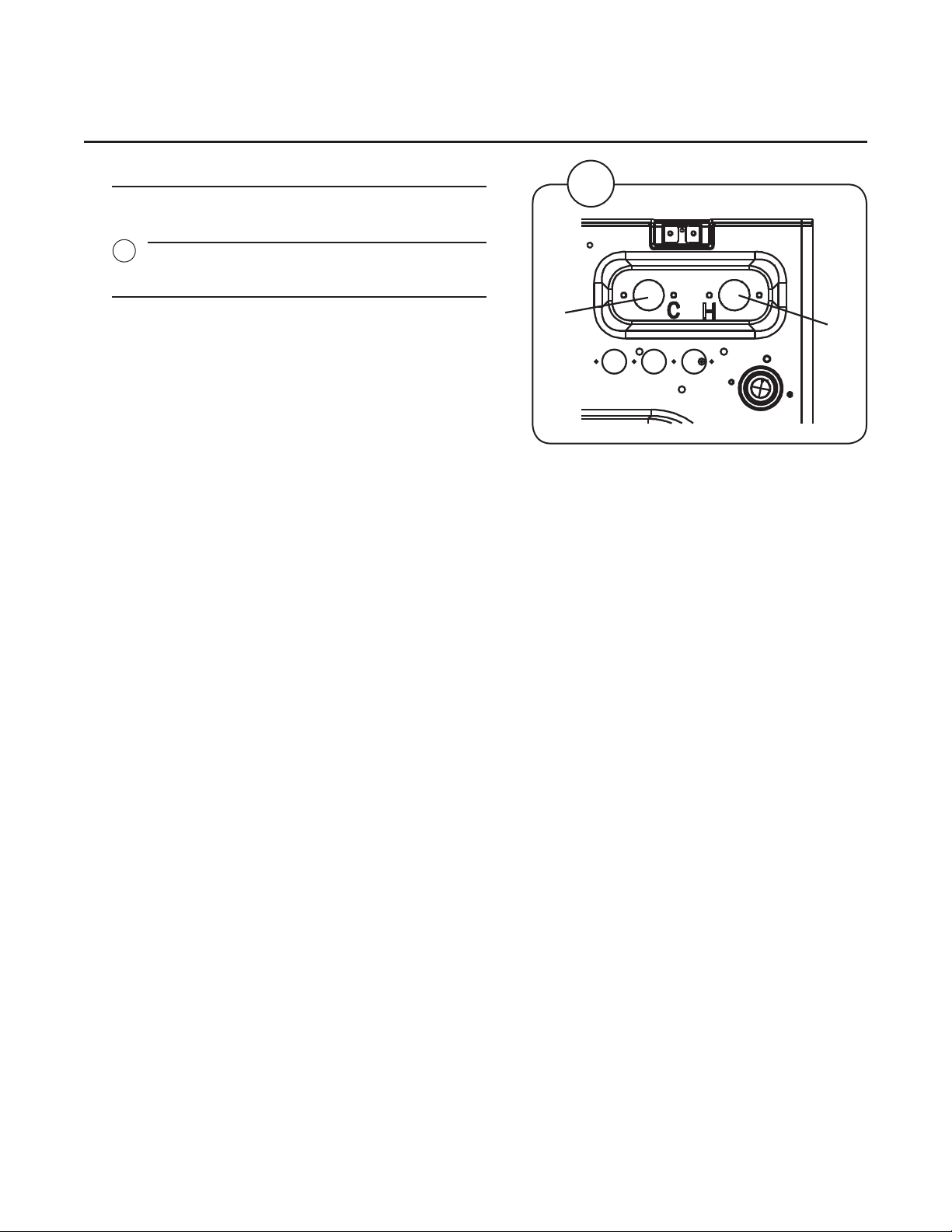
Fig.
2
1
1
Installation
Water Type Water Connection
1 2
Cold and
Hot Cold Hot
3:2
1
4:1
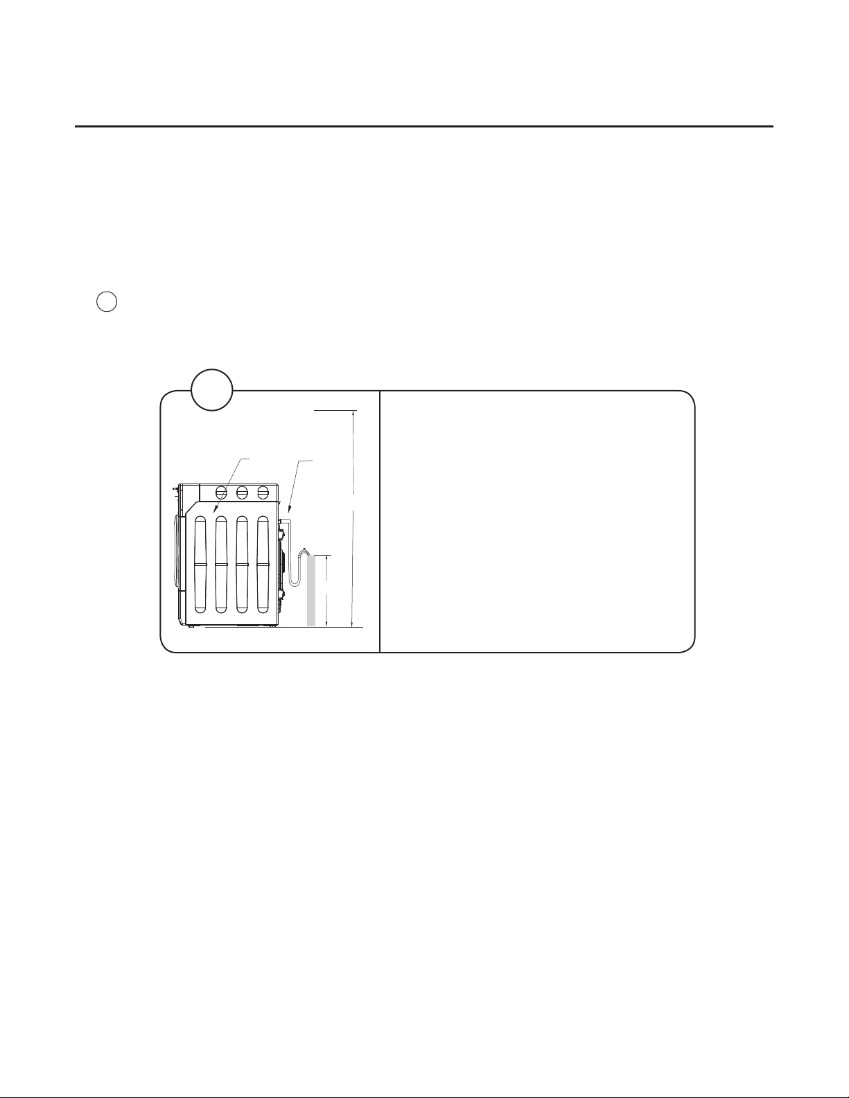
Drain Connection
Connect the machine’s drain hose to the back of the washer, using the spring clamp
provided in the accessories package. Avoid sharp bends in the hose which may prevent
proper draining.
• You can connect the drain hose to a sewer stand pipe. If you do this, make sure
Fig.
1
that the outlet hose will not come out of the stand pipe.
• You can connect the drain outlet to a sink or basin. If you do this, make sure the
outlet hose will not come out of the sink or basin.
Installation
1
Legend
C
D
A
B
A. 94 inches (239 centimeters) maximum
B. 30 inches (76 centimeters) minimum
OR placed directly in a drain basin or
trough making sure the end of the hose
is never submerged.
C. Machine
D. Drain outlet hose
Installation
5:1
Electrical installation must be carried out by
licensed, qualied personnel!
All optional equipment connected must be
EMC-approved to EN 50081-1 or EN 50082-
2.
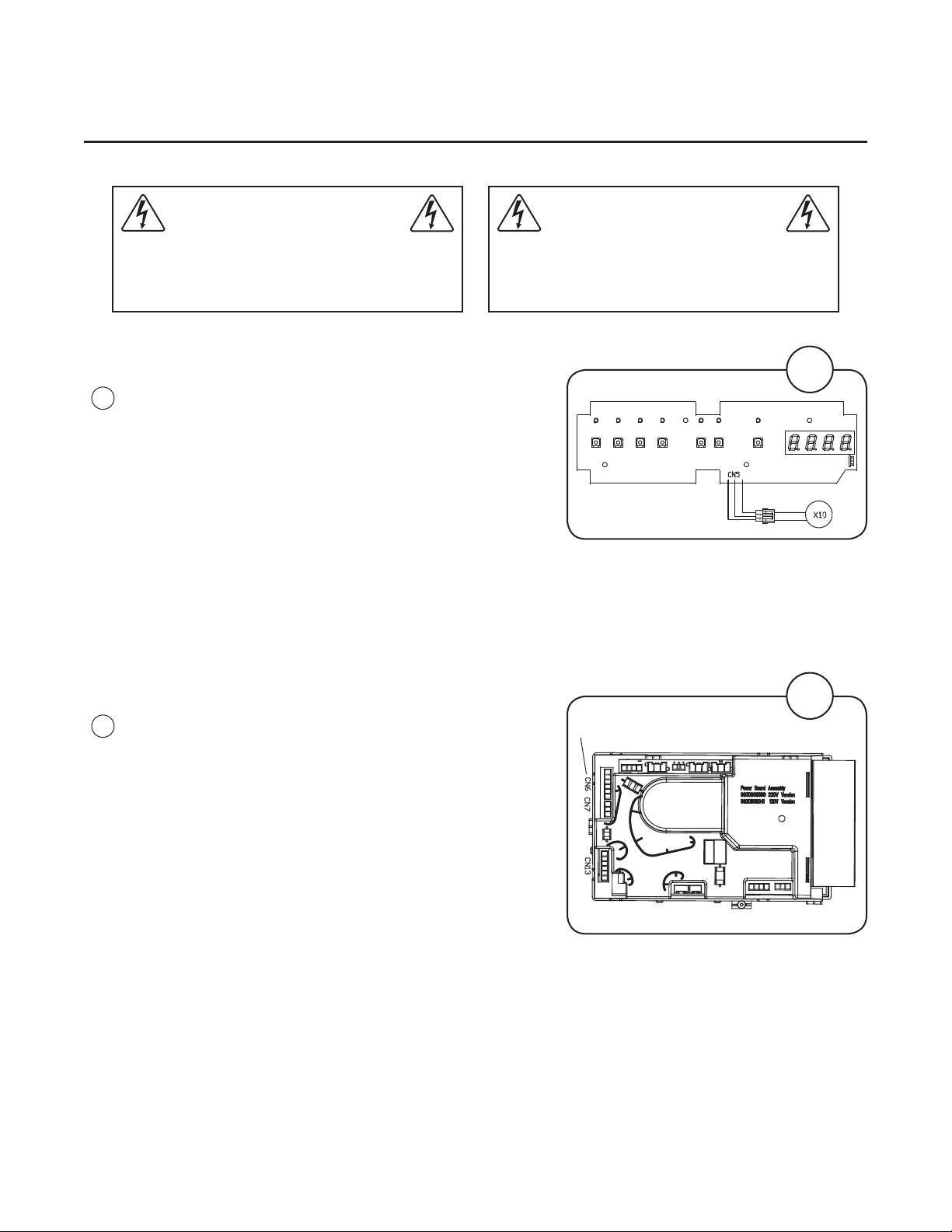
ConnectionofExternalPriceReductionControlSignal
Optional harness 0020400145C is available for price
Fig.
reduction (promotion) activation. Contact Laundrylux
1
for more information about other timer-based kits that
are available for this function. The harness mates with
a connector on the machine’s front main control circuit
board.The price reduction harness carries a +5VDC
signal lead, and a ground lead. When the leads are
connected together (using an external switch or relay
contact), the price reduction mode is activated.
NOTE: Each machine must be connected to a separate
switch or relay contact!! Refer to the machine’s operating
manual for information related to programing a discount.
ConnectionofExternalLiquidSupplySignals
Fig.
The machine can provide three “trigger signals for
external liquid supply injector pumps. The signals are
2
120V AC, and must, therefore, be routed and connected
in accordance with applicable codes.
Liquid supply signals connector.
1
2
CN1CN2CN3CN4CN5
Follow the instructions provided in the optional “Liquid
Supply Kit” (PN 096445), to connect the liquid supply
trigger signal harness to CN6 on the power module at
the right-rear corner of the machine, and to your pumps.
The trigger signal harness in the kit has 6 leads,
CN22CN23
CN17 CN18
with signals as follows:
CN6-1: RED WIRE: DETERGENT SIGNAL
CN6-2: BLACK WIRE: BLEACH SIGNAL
CN6-3: BROWN WIRE: SOFTENER SIGNAL
CN6-4, 5, 6: BLUE WIRES: COMMON (120 VAC)
Each trigger signal is activated for 30 seconds at the start of the appropriate segment of a
wash program. Detergent, bleach, and softener are then pumped into the corresponding
compartments of the soap dispenser, which continue to ush for the duration of the ll.
5:2
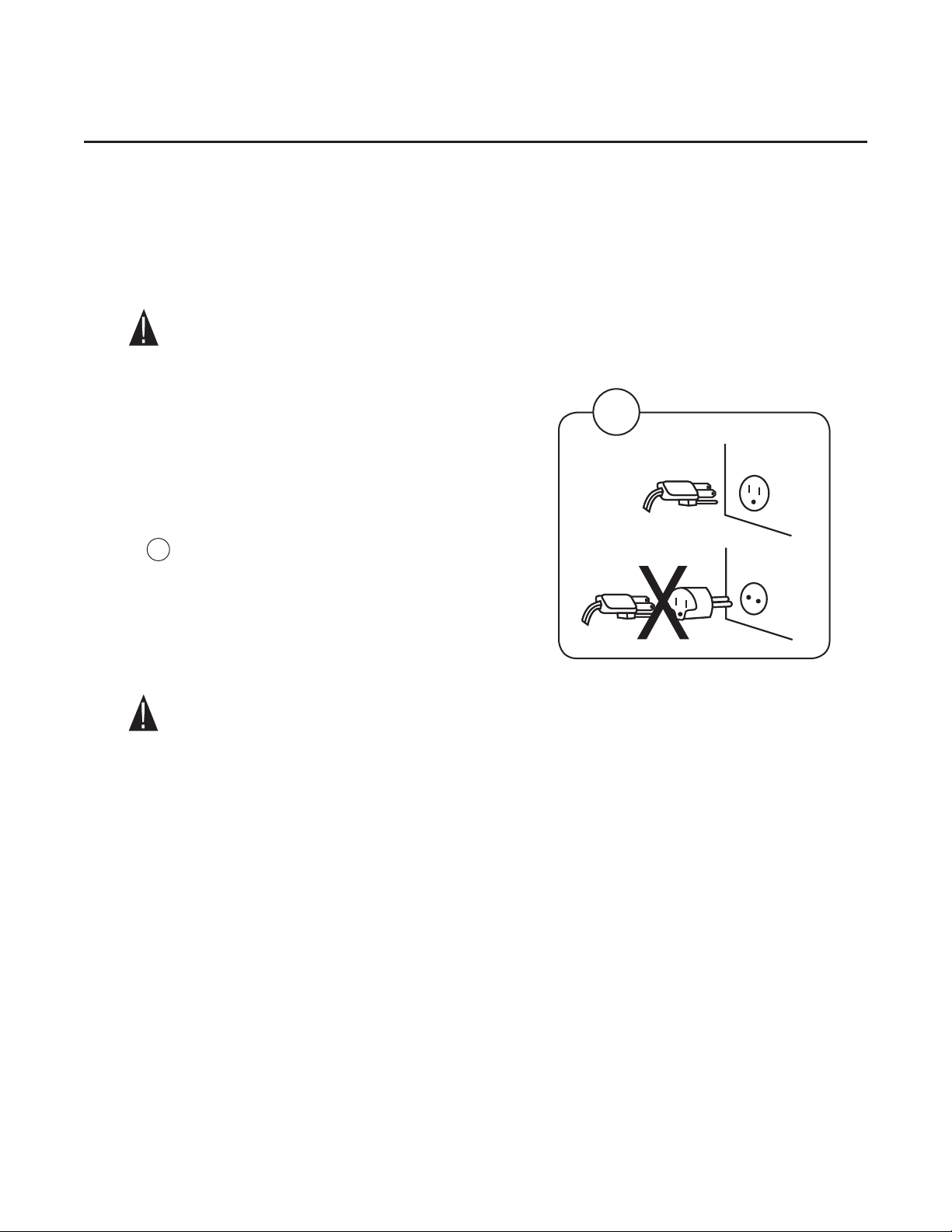
Electrical Connections
This appliance must be grounded. In the event of an electrical short circuit, grounding reduces
the risk of electric shock by providing an escape wire for the electric current. This appliance is
equipped with a cord having a grounding wire with a grounded plug. The plug must be inserted
into an outlet that is properly installed and grounded.
• Improper use of the plug can result in a risk of electric shock.
• Consult a qualied electrician or service person if the grounding instructions are
not completely understood or if doubt exists as to whether the appliance is properly
grounded.
Installation
Wiring Requirements:
• This appliance must be plugged into a 15 or 20A
120 VOLT, 60 HZ GROUNDED OUTLET.
NOTE: Where a standard two-prong outlet is
encountered, it is the personal responsibility
Fig.
and obligation of the consumer to have it
1
replaced with a properly grounded three
prong outlet.
1
Extension Cords:
DO NOT use an extension cord with this product.
Power Interruptions
Occasionally there may be power interruptions due to thunderstorms or other causes.
Following a power outage, the machine will resume operation at the point where it was when
the power failed. During a power failure, the loading door will UNLOCK a few minutes after the
drum has stopped turning. This allows garments to be removed in the event of a prolonged
power outage.

Function Checks
Function Checks
Perform the following checks once the machine is installed:
• Open the water supply valves.
• Press the START button or, if needed, insert coins and press START.
Check:
• that the drum rotates normally and that there are no unusual noises.
• that there are no leaks in water supply/drain connections.
• that water passes through the detergent compartment and fabric conditioner
compartments.
• that the door cannot be opened using reasonable force during a program.
6:1
7:1
Preventive Maintenance
To keep your machine in proper working order, follow the preventive maintenance
recommendations provided below.
The maintenance interval should be adjusted according to machine usage.
Leave the loading door open when the machine is not in use.
Daily
• Check the door and door lock:
- Open the door and try starting the machine. The machine MUST NOT START.
- Close the door, start the machine and try opening the door using reasonable
force. IT MUST NOT BE POSSIBLE TO OPEN THE DOOR WHILE THE
MACHINE IS OPERATING!
- Check that the door does not leak.
- Clean the door seal, removing any detergent and lint.
• Check that there are no indications of leaks behind or around the machine.
• Clean out any residue remaining in the detergent dispenser.
• Use a soft wash cloth and mild detergent to clean door and plastic panels.
• Inspect liquid chemical tubing and connections for leaks. Repair as necessary.
EveryThirdMonth(referthisservicetoqualiedpersonnel)
To be carried out by
qualiedpersonnel.
• Check the drain pump strainer and remove any accumulated lint and debris.
• Inspect the interior of the machine (during an actual wash cycle to ensure that no
leaks are noticed) by:
- Turning off the main power switch of the machine.
- Remove the top panel.
- Start a wash program.
- KEEP CLEAR OF MOVING PARTS WHILE MACHINE IS OPERATING!!
- Inspect all internal hoses, seals and gaskets for signs of leakage.
Repair as necessary.
- Stop the machine and disconnect the power. Turn off the water supply and check
that the water inlet screens are clear of debris. Dirty screens result in longer ll
times, reducing productivity.
- Inspect the drive belt. Adjust the tension or replace as necessary.
- Check that there are no signs of leakage on the oor beneath the machine. Locate
and repair any leak.
Contact your local dealer, or Laundrylux Technical Support at (516) 371-0700 if you
have questions regarding installation, operation, or maintenance of your machine.

Sales and Administration: (516) 371-4400
Spare Parts: (516) 371-2000
Technical Support: (516) 371-0700
En Mexico: 001-800-010-1010
461 Doughty Blvd., Inwood, NY 11096
laundrylux.com
 Loading...