

Wascom EMERALD W75ES, EMERALD W185ES, EMERALD W105ES, EMERALD W125ES Operating & Maintenance Manual
Page 1
WARNING: ALL OPERATING AND MAINTENANCE PROCEDURES SHOWN ON THE NEXT
PAGE OF THIS MANUAL MUST BE FOLLOWED DAILY FOR PROPER OPERATION OF
YOUR WASCOMAT MACHINE.
PLEASE ENTER THE FOLLOWING INFORMATION AS IT APPEARS ON THE WASHER
DATA PLATE LOCATED AT TOP LEFT OF THE REAR PANEL. SERIAL NUMBER IS ALSO
LOCATED ON A STICKER ON THE INSIDE OF THE DOOR.
MAKE CERTAIN TO KEEP THIS MANUAL IN A SECURE PLACE FOR FUTURE
REFERENCE.
MACHINE TYPE OR MODEL
MACHINE SERIAL NUMBER(S)
ELECTRICAL CHARACTERISTICS:________ VOLTS, _______ PHASE, ______ HZ.
OPERATING & MAINTENANCE MANUAL
WASCOMAT
W75ES – W105ES – W125ES – W185ES
EMERALD SERIES
471 1562-66/01
95.32
Page 2

NOTICE TO: OWNERS, OPERATORS AND DEALERS OF WASCOMAT MACHINES
IMPROPER INSTALLATION AND INADEQUATE MAINTENANCE, POOR HOUSEKEEPING AND WILLFUL
NEGLECT OR BYPASSING OF SAFETY DEVICES MAY RESULT IN SERIOUS ACCIDENTS OR INJURY.
TO ASSURE THE SAFETY OF CUSTOMERS AND/OR OPERATORS OF YOUR MACHINE, THE FOLLOWING MAINTENANCE CHECKS MUST BE PERFORMED ON A DAILY BASIS.
1. Prior to operation of the machine, check to make certain that all operating instructions and
warning signs are affixed to the machine and legible. (See the following page of this manual
for description and location of the signs.) Missing or illegible ones must be replaced immediately. Be sure you have spare signs and labels available at all times. These can be
obtained from your dealer or Wascomat.
2. Check the door safety interlock, as follows:
(a) OPEN THE DOOR of the machine and attempt to start in the normal manner:
For coin-operated models, select a program, insert the proper coins and press the
START button.
For manually operated models, select a cycle and press the START button.
THE MACHINE(S) SHOULD NOT START !
(b) CLOSE THE DOOR and press the START button. Now attempt to
open the door by turning the door handle. The door should remain locked!
If the machine can start with the door open, or can continue to operate with the
door unlocked, the door lock is no longer operating properly. The machine
must be placed out of order and the lock immediately replaced.
(See the door lock section of the manual.)
3. DO NOT UNDER ANY CIRCUMSTANCES ATTEMPT TO BYPASS OR REWIRE ANY OF
THE MACHINE SAFETY DEVICES AS THIS CAN RESULT IN SERIOUS ACCIDENTS.
4. Be sure to keep the machine(s) in proper working order: Follow all maintenance and
safety procedures. Further information regarding machine safety, service and parts can be
obtained from your dealer or from Wascomat through its Teletech Service Hotline - (516)
371-0700.
All requests for assistance must include the model, serial number and electrical characteristics as
they appear on the machine identification plate at the top rear of the washer. Insert this information
in the space provided on the previous page of this manual. You can also find the serial number on
a sticker on the inside of the door.
5. WARNING: DO NOT OPERATE MACHINE(S) WITH SAFETY DEVICES BYPASSED, REWIRED OR
INOPERATIVE! DO NOT OPEN MACHINE DOOR UNTIL DRUM HAS STOPPED ROTATING!
Page 3
DO NOT ATTEMPT TO OPEN DOOR
UNTIL PROGRAM HAS FINISHED AND
DRUM HAS STOPPED ROTATING.
WARNING !
If you need to order more safety or warning
signs, call Wascomat's parts department at
516-371-2000, or call your local dealer.
471 7651-17
471 76 62 02
SAFETY AND WARNINGS SIGNS
Replace If Missing Or Illegible
One or more of these signs must be affixed on each machine as indicated, when not included as part of the front instruction panel.
LOCATED ON THE OPERATING INSTRUCTION SIGN OF THE MACHINE:
LOCATED AT THE REAR OF THE MACHINE:
INSTALLATION AND MAINTENANCE WARNINGS
1. This machine MUST be securely bolted to an uncovered concrete floor, according to
the installation instructions, to reduce the risk of fire and to prevent serious injury, or
damage to the machine.
2. If installed on a floor of combustible material, the floor area below this machine must
be covered by a metal sheet extending to the outer edges of the machine.
3. This machine MUST be connected to a dedicated electrical circuit to which no other
lighting unit or general purpose receptacle is connected. Use copper conductor only.
4. This machine MUST be serviced and operated in compliance with manufacturer's
instructions. CHECK DOOR LOCKS EVERY DAY FOR PROPER OPERATION TO PRE
VENT INJURY OR DAMAGE. IF THE DOOR LOCK FAILS TO OPERATE PROPERLY,
PLACE THE MACHINE OUT OF ORDER UNTIL THE PROBLEM IS CORRECTED.
5. Disconnect power prior to servicing of machine.
6. To remove the top panel for service on those models on which it is secured by screws
at the rear, first remove the screws. Be certain to reinstall them when remounting the
top panel. To remove the top panel for service on those models on which it is secured
by one or two keylocks, use the keys originally shipped in the drum package. Be
certain to relock after remounting the top panel.
MANUFACTURED BY WASCATOR
DISTRIBUTED BY WASCOMAT INWOOD, NEW YORK, USA
LOCATED ON THE DOOR:
Page 4

Contents
Wascomat W75ES • W105ES • W125ES • W185ES
EMERALD SERIES
Introduction ......................................................................1
Technical data.................................................................. 2
Installation ........................................................................7
Operating Instructions.................................................... 15
Fault-finding & Servicing Programs ............................... 21
Programming..................................................................25
Wash Cyclels .................................................................29
Mechanical and Electrical Design .................................. 38
Maintenance...................................................................55
Troubleshooting .............................................................56
The manufacturer reservs the right to make changes to design and
material specifications.
Safety instructions
• The machine is designed for water washing only.
• The machine must not be used by children.
• All installation operations are to be carried out by qualified
personnel. Licensed personnel are necessary for all electric
power wiring.
• The interlock of the door must be checked daily for proper
operation and must not be bypased.
• Any water leaks must be repaired immediately.
• All service personnel must be fully familiar with the operating
manual before attempting any repair or maintenance of the
machine.
• The machine must not be sprayed with water, otherwise short
circuiting may occur.
• Volatile or flammable liquids are not to be used.
Page 5
1
Introduction
General
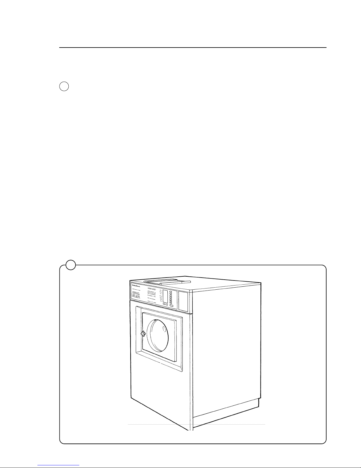
Wascomat EMERALD SERIES washer/extractors have been developed to
meet the needs of state-of-the-art professional laundromats. EMERALD
models are unique because you can program different prices for the seven
wash cycles, giving the customer a real choice and allowing you to maximize revenue by charging what each cycle is worth. In addition, you can
charge a higher price if the customer selects the Extra Extract option. Using
an external clock and wiring harness, these models may be programmed to
lower prices by any percentage between any hours of any days, for the
ultimate in pricing flexibility!
The seven cycles offer different water temperatures, wash times, extraction
times, and normal or gentle drum rotation. EMERALD SERIES washers
achieve maximum environmental efficiency because only the minimum
amount of water is used for each cycle, which vary in duration.
When ordering spare parts or contacting Wascomat or your dealer for
service, always give the machine serial number, model, voltage and other
electrical characteristics appearing on the data plate at the top left of the
rear panel of the machine. The serial number is also printed on a sticker
inside the door.
KEEP THIS MANUAL IN A SAFE PLACE FOR FUTURE REFERENCE!
G135
1
Fig.
1
Page 6

Technical data
2
Technical data Wascomat W75ES EMERALD SERIES
Dry load capacity up to 18 lbs
Overall dimensions Width 660 mm 26 in
Depth 678 mm 26 11/16 in
Height 1050 mm 41 11/32 in
Net weight 107 kg 235 lbs
Dyn force 1.2±2.6 kN 290±620 lbs. force
Crated dimensions Volume 0.62 m
3
21.9 cu.ft
Weight 117 kg 257 lbs
Inner drum Diameter 520 mm 20 1/2 in
Depth 356 mm 14 in
Volume 75 litre 2.7 cu.ft
Speed of rotation Wash 54 r.p.m.
Extraction 543 r.p.m.
G-factor During wash 0.8
During extraction 90
Motor speed During wash 344 r.p.m.
During extraction 3514 r.p.m.
Voltage requirements Choice:
120 V 1-phase 60 Hz
or
208-240 V 3-Phase 60 Hz
Rated output power Motor, wash, 3-phase 110 W
0.15 HP
Motor, extract., 3-phase 550 W
0.75 HP
Motor, wash, 1-phase 110 W
0.15 HP
Motor, extract., 1-phase 370 W
0.5 HP
Overcurrent protection Three-phase 15 A
Single-phase 20 A
Water connections
Recommended water pressure 2-6 kp/cm
2
25-85 psi
Hose connection, water 20 DN 3/4 in
Hose connection, drain 74 mm 3 in
Page 7

Technical data
3
Technical data W105ES EMERALD SERIES
Dry load capacity up to 25 lbs
Overall dimensions Width 660 mm 26 in
Depth 795 mm 31 5/16 in
Height 1050 mm 41 11/32 in
Net weight 147 kg 323 lbs
Dyn force 1.7 ±3.4 kN 408±816 lbs. force
Crated dimensions Volume 0.65 m
3
23.0 cu.ft.
Weight 158 kg 348 lbs
Inner drum Diameter 520 mm 20 1/2 in
Depth 473 mm 18 5/8 in
Volume 100 litre 3.6 cu.ft
Speed of rotation Wash 54 r.p.m.
Extraction 543 r.p.m.
G-factor During wash 0.8
During extraction 90
Motor speed During wash 344 r.p.m.
During extraction 3514 r.p.m.
Voltage requirements Choice:
120 V 1-phase 60 Hz
or
208-240 V 3-Phase 60 Hz
Rated output power Motor, wash 3-phase 150 W
0.2 HP
Motor, extract. 3-phase 900 W
1.2 HP
Motor, wash 1-phase 140 W
0.18 HP
Motor, extract. 1-phase 550 W
0.75 HP
Overcurrent protection Three-phase 15 A
Single-phase 20 A
Water connections
Recommended water pressure 2-6 kp/cm
2
25-85 psi
Hose connection, water 20 DN 3/4" in
Hose connection, drain 74 mm 3" in
Page 8

4
Technical data
Technical data Wascomat W125 ES EMERALD SERIES
Dry load capacity up to 35 lbs
Overall dimensions Width
Depth 995 mm 39 3/16 in
Height 1196 mm 47 3/32 in
Net weight 210 kg 462 lbs
Dyn force 2.4±4.8 kN 576±1152 lbs. force
Crated dimensions Volume 1.06 m
3
39 cu.ft.
Weight 222 kg 489 lbs
Inner drum Diameter 620 mm 24 1/2 in
Depth 520 mm 20 1/2 in
Volume 157 litre 5.65 cu.ft
Speed of rotation Wash 52 r.p.m.
Extraction 500 r.p.m.
G-factor During wash 0.9
During extraction 87
Motor speed During wash 330 r.p.m
During extraction 3450 r.p.m
Voltage requirements Choice:
208-240 V 1-phase 60 Hz
or
208-240 V 3-Phase 60 Hz
Rated output power Motor, wash 3-phase 300 W
0.4 HP
Motor, extract. 3-phase 1300 W
1.8 HP
Motor, wash 1-phase 280 W
0.4 HP
Motor, extract. 1-phase 1300 W
1,8 HP
Overcurrent protection Three-phase 15 A
Single-phase 20 A
Water connections
Recommended water pressure 2-6 kp/cm
2
25-85 psi
Hose connection, water 20 DN 3/4" in
Hose connection, drain 74 mm 3" in
Page 9

Technical data
Technical data Wascomat W185 ES EMERALD SERIES
Dry load capacity up to 50 lbs
Overall dimensions Width 860 mm 33 7/8 in
Depth 1085 mm 42 3/4 in
Height 1315 mm 51 3/4 in
Net weight 264 kg 582 lbs
Dyn force 3.1±5.2 kN 744±1248 lbs. force
Crated dimensions Volume 1.42 m
3
50.2 cu.ft.
Weight 275 kg 606 lbs
Inner drum Diameter 700 mm 27 9/16 in
Depth 600 mm 23 5/8 in
Volume 230 litre 8.1 cu.ft
Speed of rotation Wash 45 r.p.m.
Extraction 455 r.p.m.
G-factor During wash 0.8
During extraction 81
Motor speed During wash 360 r.p.m
During extraction 3480 r.p.m
Voltage requirements Choice:
208-240 V 1-phase 60 Hz
or
208-240 V 3-Phase 60 Hz
Rated output power Motor, wash 3-phase 400 W
0.55 HP
Motor, extract. 3-phase 2000 W
2.7 HP
Motor, wash 1-phase 400 W
0.55 HP
Motor, extract. 1-phase 1800 W
2.4 HP
Overcurrent protection Three-phase 15 A
Single-phase 20 A
Water connections
Recommended water pressure 2-6 kp/cm
2
25-85 psi
Hose connection, water 20 DN 3/4" in
Hose connection, drain 74 mm 3" in
5
Page 10

Outline and dimensions
Technical data
6
1 Cold water
2 Hot water
3 Hot water (W185)
4 Drain outlet
5 Electrical + price reduction connections
6 Door
7 Slip-lock door handle
8 Emerald control panel
9 Coin-meter
10 Supplies compartments
W75 W105 W125 W185
mm inches mm inches mm inches mm inches
A 1050 41 5/16 1050 41 5/16 1196 47 1/16 1315 51 3/4
B 437 17 3/16 437 17 3/16 465 18 5/16 540 21 1/4
C 660 26 660 26 775 30 1/2 860 33 7/8
D 678 26 11/16 795 31 5/16 995 39 3/16 1085 42 11/16
E 895 35 1/4 895 35 1/4 1040 40 15/16 1160 45 11/16
F 100 3 15/16 100 3 15/16 100 3 15/16 100 3 15/16
G 125 4 15/16 125 4 15/16 270 10 5/8 260 10 1/4
H 980 38 9/16 980 38 9/16 1135 44 11/16 1255 49 7/16
J – – – – – – 1215 47 13/16
K 890 35 890 35 1035 40 3/4 1155 45 1/2
L – – – – – – 295 11 5/8
M 205 8 1/6 205 8 1/16 205 8 1/16 205 8 1/16
N 160 6 5/16 160 6 5/16 160 6 5/16 160 6 5/16
3210
D
C
10
8
7
6
9
B
A
E
4
G
F
KJH
5
2
3
1
M
N
L
Page 11
W75 W105 W125 W185
mm inches mm inches mm inches mm inches
A 364 14 11/32 481 18 15/16 508 20 600 23 2/3
B 593 23 11/32 710 27 15/16 910 35 13/16 960 37 3/4
C 648 25 1/2 760 29 15/16 1031 40 9/16 1078 42 7/16
D 100 4 100 4 142 5 9/16 142 5 9/16
E 530 20 7/8 530 20 7/8 600 23 5/8 700 27 9/16
G 700 27 9/16 700 27 9/16 800 31 1/2 880 34 2/3
H 643 25 5/16 715,6 28 3/16 786 30 15/16 922 36 1/8
I - - - - 991 39 1090 42 7/8
K - - - - 281 11 236 9 7/16
Installation
2
3
4
0271
1677
1132
Installation
Machine foundation
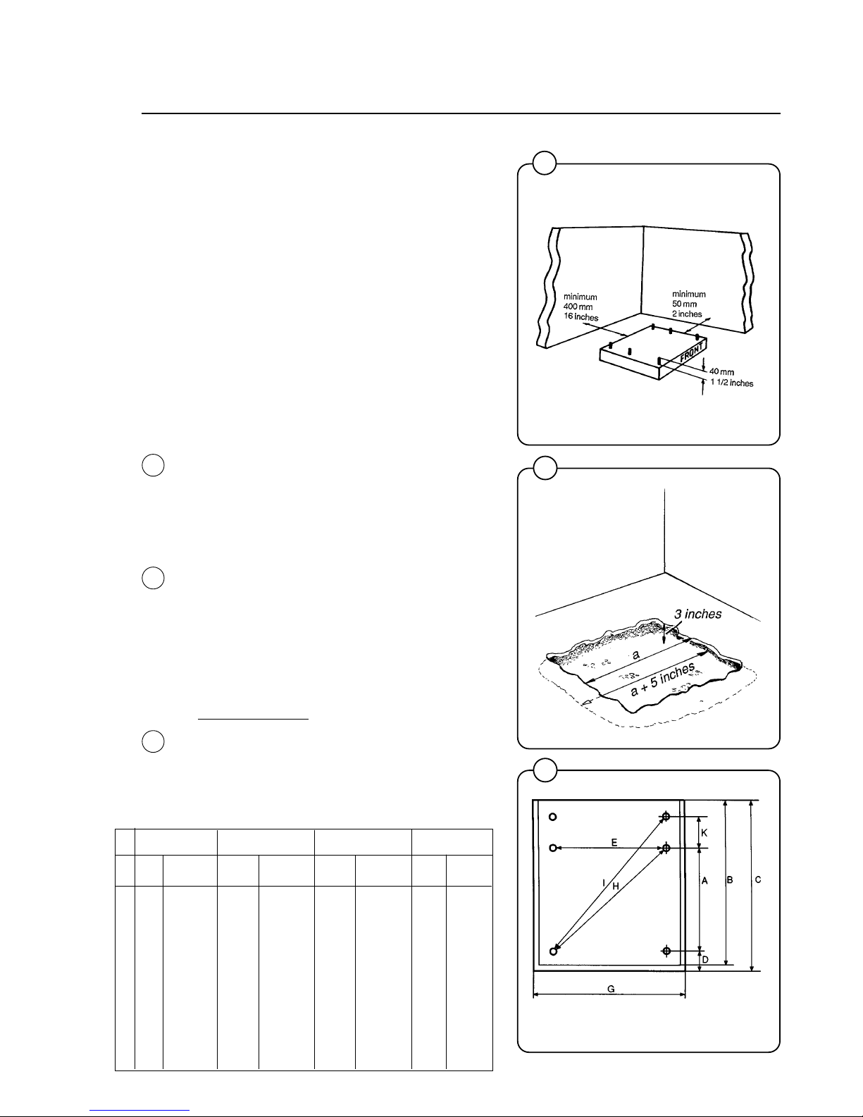
The machines are designed to be securely bolted
to a concrete pad. A template showing the size of
the pad and positioning of the bolts is delivered
with each machine.
For installation on an existing concrete floor, the
floor must be at least 8" thick and of good quality.
If the floor does not meet these requirements,
then a 6-8" high concrete pad should be made. A
prefabricated steel base is available for mounting
machines without pouring a pad.
Follow the instructions below when making a
concrete foundation:
1. Decide where to place the machine and
consider maintenance requirements, i.e.
determine a suitable distance from the rear of
the pad to the wall, and the distance from the
pad to the nearest side wall. The distance
should be at least 16 and 12 inches,
respectively. Leave 3/4'' between washers.
2. Break up the floor to a minimum depth of 3
inches, making sure that the sides of the hole
slope away - the bottom of the hole should be
5 inches longer than the upper length.
3. Wet the hole well. Brush the bottom and sides
with cement grout.
4. Prepare a casing and fill with 3.000 PSI
concrete to form pad. Make sure the
foundation is level.
5.
Use the template to position the bolts
correctly. Bolts are to extend 1 1/2" above the
concrete.
NOTE: A prefabricated steel frame, designed
to be placed in the concrete instead of the
individual mounting bolts, is available.
7
Fig.
2
Fig.
3
Fig.
4
B = machine outline to edge of front panel
C, G = minimum foundation for one machine
Page 12
Installation
5
6
7
0274
0950
1133
NOTE: Install the W105ES using the front and
rear pairs of bolt holes. The middle pair is
used when a W105ES is being installed in
replacement of a W73, W74 or W75 washer.
In that case the rear bolt holes are not
necessary but may also be used.
NOTE: If you form a lip on top of the concrete
pad in front of the washers, be sure you leave
enough room to remove the bolts which
secure the bottom of the front panel and
enough room to swing out and remove the
panel!
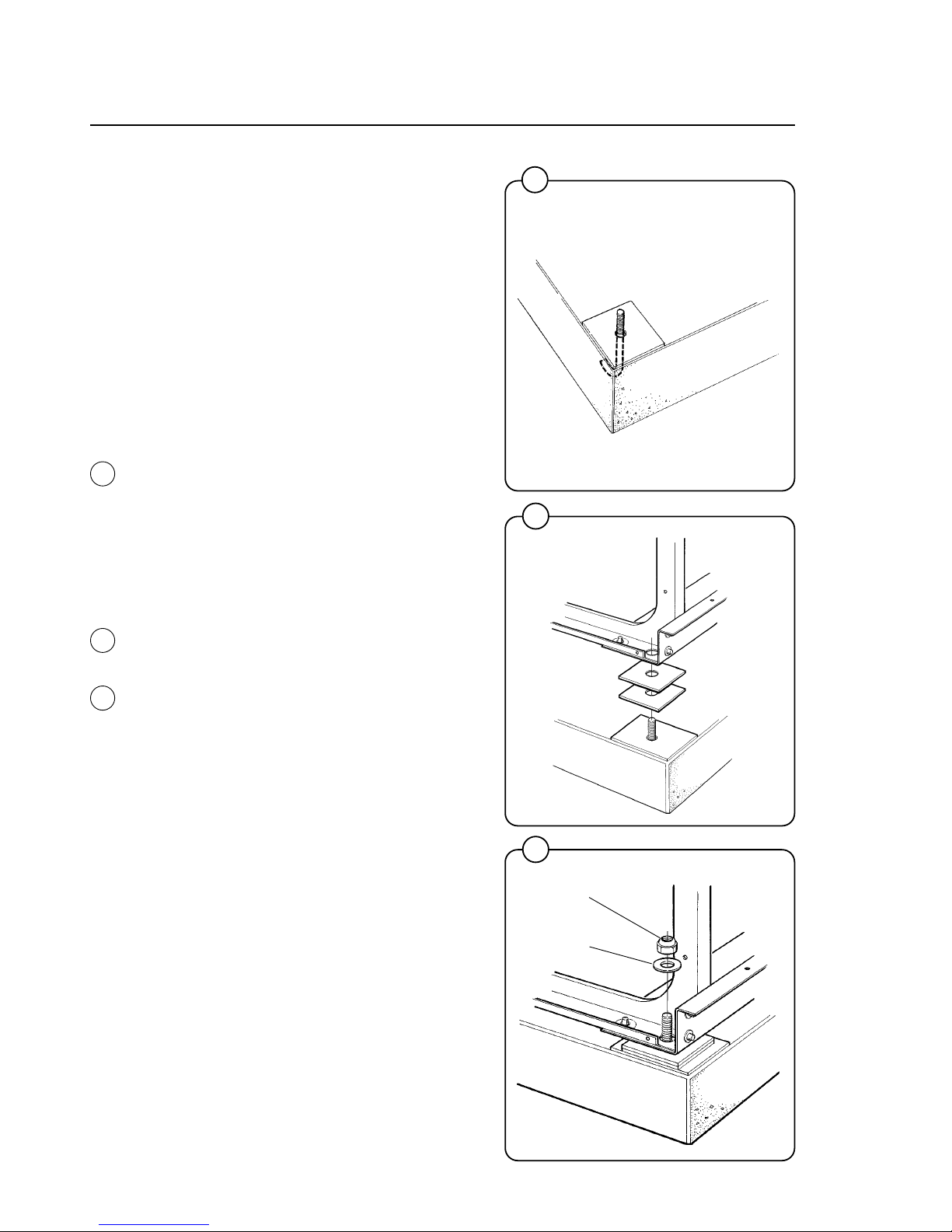
Mechanical installation
• Place wide steel shims on the concrete foundation over the bolts.
• Lift the machine and lower it in position. Never
use the door or the door handle to lift or lower
the machine.
• Check that the machine is level front-to-rear
and side-to-side and standing firmly on the
four (W75, W105) or six (W125 W185) supporting points. Spacing washers must be
mounted if one or more of these points is not
resting against the concrete.
• Place flat washers over the foundation bolts
and secure the machine in position by tightening the self-locking nuts. See illustration
below.
• Check and tighten the nuts every week for the
first month.
selflocking
nut
flat washer
8
Fig.
5
Fig.
6
Fig.
7
Page 13

9
Installation
10
1830
1838
1839
11
1137
Electrical Connections:
Although the machines are fitted with a thermal
overload in the motor windings, a separate threephase common-trip circuit breaker must be
installed for all three-phase machines.
For proper circuit breaker protection, check the
data plate at the rear of the machine. Also
consult local electrical code for special
requirements.
Connect L1, L2, L3 and ground wires according
to the markings of the terminal block. The cable
is to hang in a loose loop, supported by the clip
of the terminal block.
After installation, do the following:
Check the incoming power for any high voltage
leg by measuring voltage from each leg to ground. If a high leg is present, connect that line to
L2 on the terminal block, which goes to the motor
circuit.
Start the machine and check that the drum
rotates in the proper direction during extraction,
i.e. counter-clockwise when seen from the front.
If the drum rotates in the wrong direction switch
lines L1 and L3.
Check that the transformer on the control unit is
correctly tapped for the incoming voltage. The
different voltage alternatives are printed on the
transformer circuit board.
8
9
Fig.
8
Fig.
9
Fig.
10
Fig.
11
Page 14
10
Installation
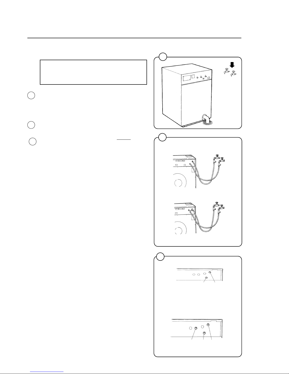
Water Connections:
NOTE
All plumbing must conform to national
and local plumbing codes.
Incoming water lines do not require non-return or
back flow prevention valves, as the machine is
already fitted with an approved siphon breaker.
However, all incoming lines must be fitted with
shut-off valves.
• Water inlets are labelled for hot and cold
water connection. The W185 has two hot
water and one cold water connections.
• Flush the water lines thoroughly
before
hooking hoses up to the washers, then check
that all water valves are attached tightly and
inlet screens not clogged. Use teflon pipe tape
if necessary to ensure watertightness.
• Use 1/2" or 3/4" diameter reinforced rubber
hosing not to exceed 6 feet in length. Let the
hoses hang in a loop. Do not use rigid piping.
Never force a hose onto the threads or you
may cause cross-threading and leaks. If this
occurs, place the threaded portion of the hose
over the valve threads and push forward
firmly, to catch the next thread. Then tighten.
Depending how large your laundry is, your
main incoming water line will generally be
between 1-1/2" to 3" diameter to assure
adequate water supply.
Fig.
12
Fig.
13
Fig.
14
12
13
1832
W 75, W105, W125
W 185
1870
14
hot water cold water
1846
W 75, W105, W125
W 185
hot water cold water cold water
(to detergent supply box)
1844
Page 15

11
Installation
How to size water supply piping for Wascomat coin laundries
1. Calculate the total number of gallons of water that would be needed if all present (and
future) washers were to fill at the same time. Assume the W75 (18-lb.) uses 7 gallons
per fill; W105 (25-lb.) uses 10 gallons per fill; W125 (35-lb.) uses 14 gallons per fill‚
W185 (80-lb.) uses 20 gallons per fill; and W244 (75-lb.) uses 30 gallons per fill. If
water pipe runs of 70 feet or longer are required, multiply by 1.25 to compensate for
pipe friction which reduces flow rates.
2. Using the Flow Chart below and knowing the water pressure in the water main at your
store, select a pipe diameter that has a gallons per minute (gpm) flow rate the same or
higher than the total calculated above. The hot water line and the cold water line
supplying the washers must
each be this size diameter, since many fills are all hot or
all cold. This will assure fill times of approximately 1 minute and normal cycle times.
Wascomat washers are designed to operate at 25–85 PSI Call your local water utility
company if you do not know the water pressure in your water main.
GALLONS PER MINUTE FLOW CHART
Pipe internal Water pressure from the water main
Diameter, Inches 25 psi 40 psi 60 psi 80 psi
1/2 21 gpm 27 gpm 33 gpm 37 gpm
3/4 36 46 56 64
1 63 85 104 120
1-1/4 112 148 181 208
1-1/2 160 210 257 297
1-3/4 209 273 334 385
2 257 335 410 473
2-1/2 419 548 670 772
3 580 760 930 1070
3-1/2 650 840 1025 1185
4 720 920 1120 1300
5 1500 1960 2400 2770
6 1930 2530 3100 3580
3. The water line from the laundry to the water main in the street must carry
double the
total gallons capacity calculated in paragraph 1. Select the correct diameter from the
Flow Chart. (You will note from the chart that two 2'' pipes do
not equal the flow rate of
a 4 inch pipe; two 1'' pipes do
not equal the flow rate of a 2 inch pipe, etc... Use the
correct gpm flow rates!)
Page 16
12
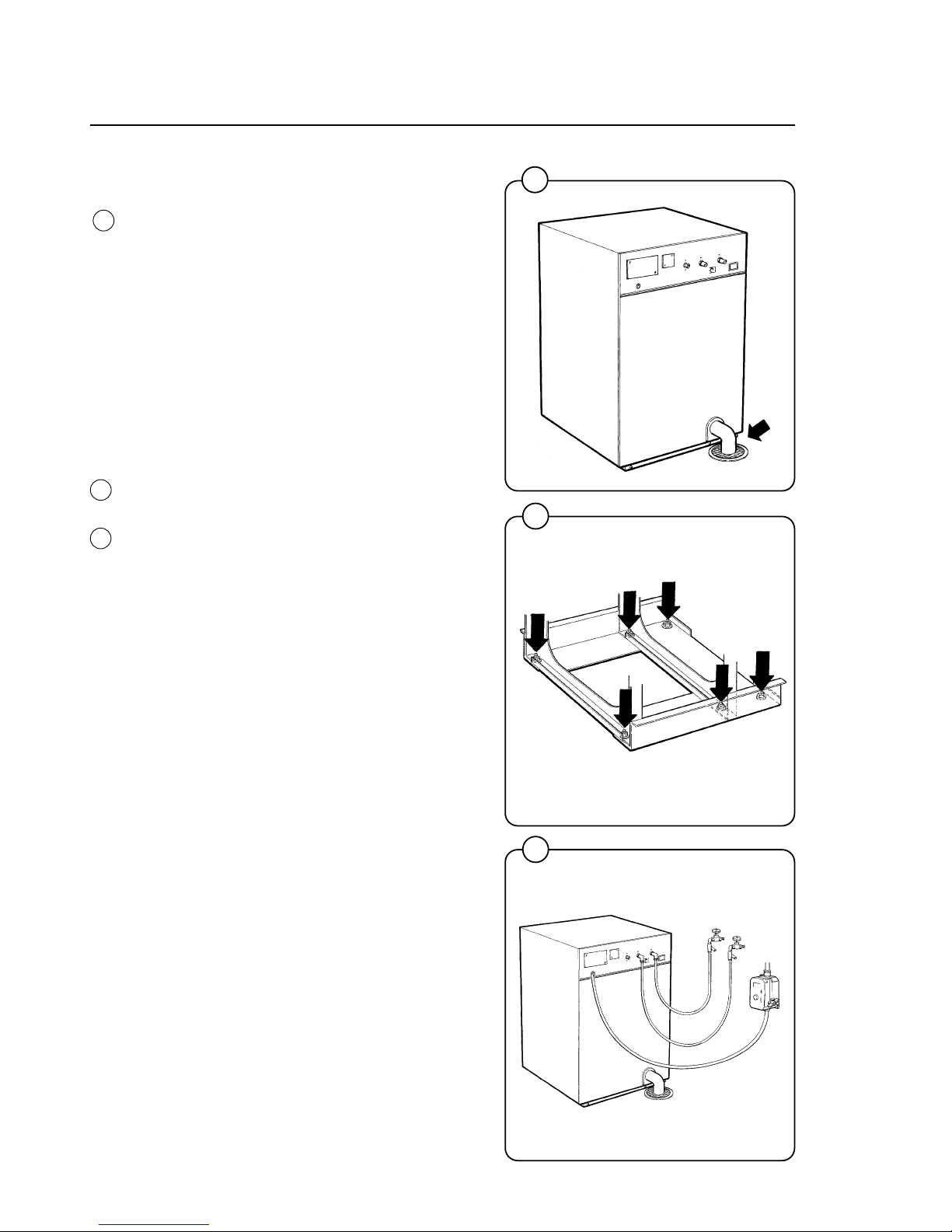
Drain Connections:
Connect a 3" (75 mm) flexible hose to the drain
outlet of the machine and clamp it securely.
The drain hose may be connected to a 2" to 3"
T- connection coming out of your main drain line,
which is typically four inches diameter, or the
washer may dump into a trough which slopes to
a drain, or directly into a floor drain as shown in
the illustration. Check local codes for required
installation procedure.
Start-up and safety checklist
Before initial start-up of a Wascomat washer the
following safety checks must be performed:
• Make sure the machine is properly bolted to
the floor and level.
• Make sure that all electrical and plumbing
connections have been made in accordance
with applicable local codes.
• Use only flexible water fill and drain hoses of
the proper length to avoid sags and kinks.
• Make sure the machine is properly grounded
electrically.
Installation
15
1833
16
1140
17
1834
Fig.
17
Fig.
16
Fig.
15
Page 17
13
Installation
18
19
1853
1854
Fig.
18
Fig.
19
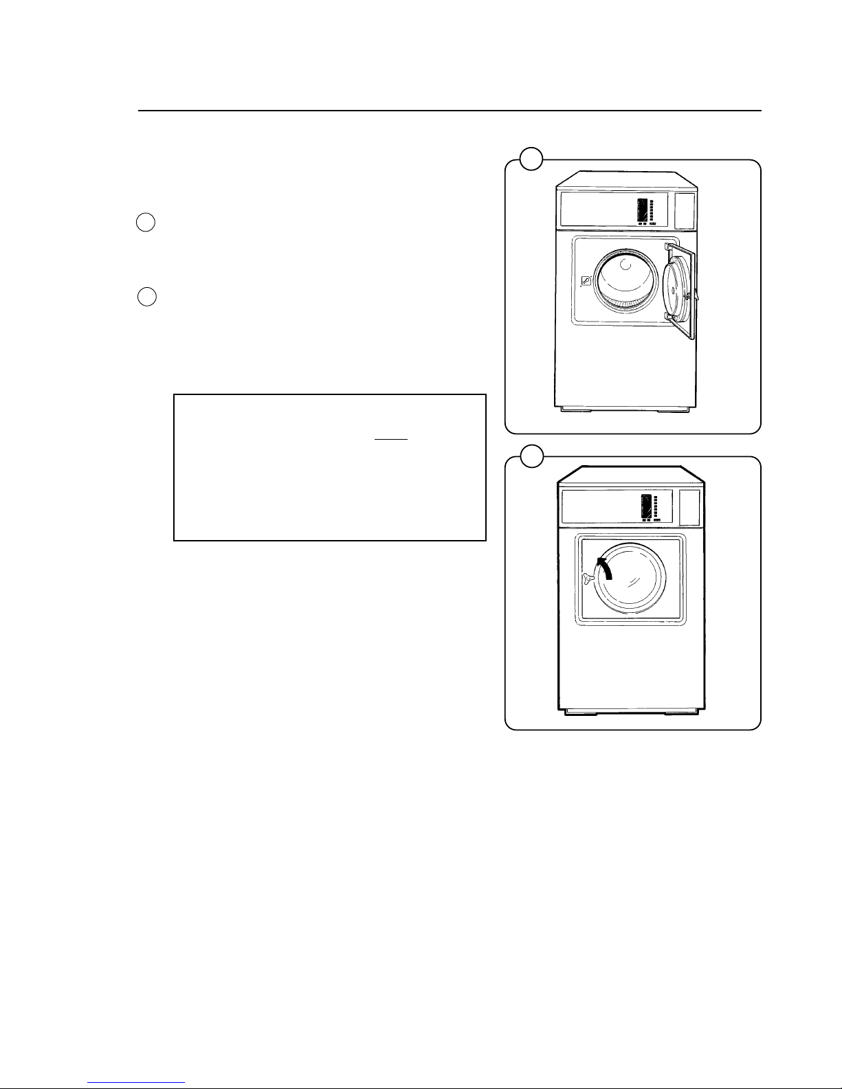
Before the machine is operated, the door lock
must be checked for proper operation as follows:
• When washer door is open, the machine must
not start. Verify this by attempting to start
washer with door open.
• When washer is in operation, the door is
locked and cannot be opened. Verify this by
attempting to open the door when the
machine is operating. If necessary, consult
this manual for proper operation of the door
lock or call a qualified serviceman.
IMPORTANT:
Door lock must be checked daily in
accordance with above procedure.
WARNING:
Before servicing Wascomat equipment,
disconnect electrical power.
If the side panels of the washer move during
extraction, remove the shipping security which
connects the top rear of the cylinder to the upper
section of the back panel. It is used to prevent
shipping damage but has no function when the
washer is installed in a laundry. In some rare
installations this bracket may transmit vibrations
to the side panels. If it does, remove the shipping
security; otherwise, leave it in place.
Page 18

14
Installation
22
1295
1835
1836
23
0958
20
21
Fig.
20
Fig.
21
Fig.
22
Fig.
23
Function control check-out list
In the cylinder you will find the warranty registration card, a copy of the warranty policy, the bolthole template, wiring diagram, and other pertinent material. The warranty card must be completed and sent to Wascomat immediately or
your warranty coverage will start from the day we
shipped the washer from our warehouse. All
other items should be placed in a safe place for
future reference.
The machine should be cleaned when the installation is completed, and checked out as detailed
below without loading the machine with clothes:
1. Check the incoming power for proper voltage,
phase and cycles.
2. Open water taps to the machine.
3. Turn on electric power.
4. Check the door lock as detailed in this
manual.
5. Select the Warm cycle and then press the
START button.
6. Run through a complete Warm cycle, checking for proper water temperature, drain operation and extract direction. To rapid advance
the timer, press and hold down the START
button until the indicator arrows reach the
desired part of the cycle.
7. Now select and run the Cold cycle. There is
no hot water in the Cold cycle so if hot water
enters the hoses are improperly connected.
Reverse the hot and cold water hoses.
8. The drum must extract in a counter-clockwise
direction as seen from the front! If it does not,
reverse incoming electric lines L1 and L3.
NOTE:
All machines are factory tested prior to
shipment. Occasionally, some residual
water may be found when the machine is
installed.
Page 19

15
2172
The keypad consists of seven wash program buttons, two option buttons
and a start button. An Information Display with illuminated symbols shows
the selected wash cycle, cycle options, steps in the wash cycle which have
been completed (indicated by squares around arrows), steps which remain
(indicated by arrows), remaining wash time, and the number of quarters
required to start the washer.
If a fault occurs then error numbers on the Information Display will refer you
to the fault code list under Fault Finding in this manual.
START
Extra
extract
Gentle
action
Hot
Warm
Cold
Delicate
Permanent Press
Quick - Wash
Heavy Soil
Heavy Soil
Prewash
Wash
Rinses
Final Extract
Extra Extract
Open door after
becomes
Add bleach
if desired
Rinse
Rinse
Add
softener
Fig.
24
24
Operating instructions
INFORMATION
DISPLAY
Page 20
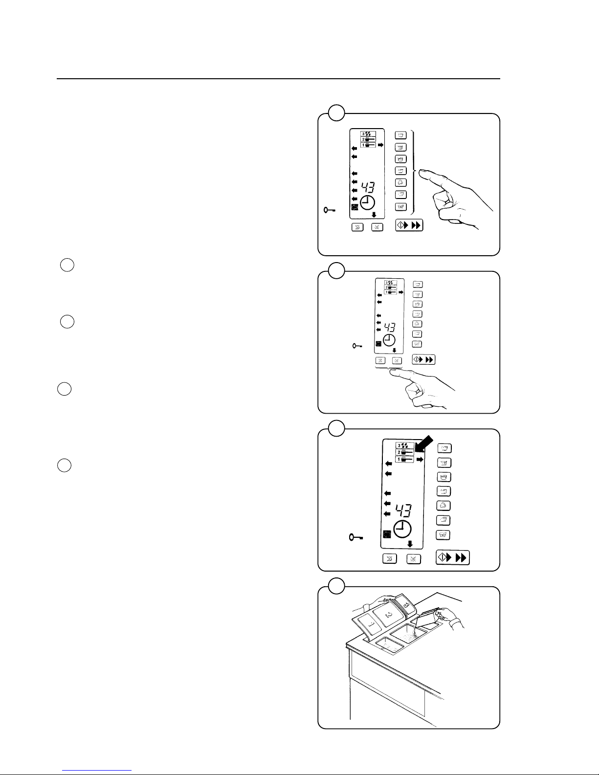
16
Operating Instructions
Preparations
Sort the wash according to the choices shown on
the control panel. Check washing tips on garment labels.
Make sure all pockets are empty and zips closed.
Load the washer and lock the door.
Washing
• Push one wash cycle button.
An arrow to the right of the control panel will
light up to show selection. Left arrows will light
to show the steps in the program.
• Select Extra Extract and/or Gentle Wash if
desired. Arrows will point to them.
• Three symbols in the Information Display
show in which compartments to put detergent
and softener.
- Prewash detergent in compartment 1.
- Mainwash detergent (and later bleach) in
compartment 2.
- Final rinse softener in compartment 3.
• You do not need more than 1/4 cup detergent
in a W75ES or W105ES, 1/3 cup in a
W125ES, or 1/2 cup in a W185ES.
0256
1302
1301
1300
Operating Instructions
Fig.
28
Fig.
27
Fig.
25
Fig.
26
25
26
27
28
Page 21
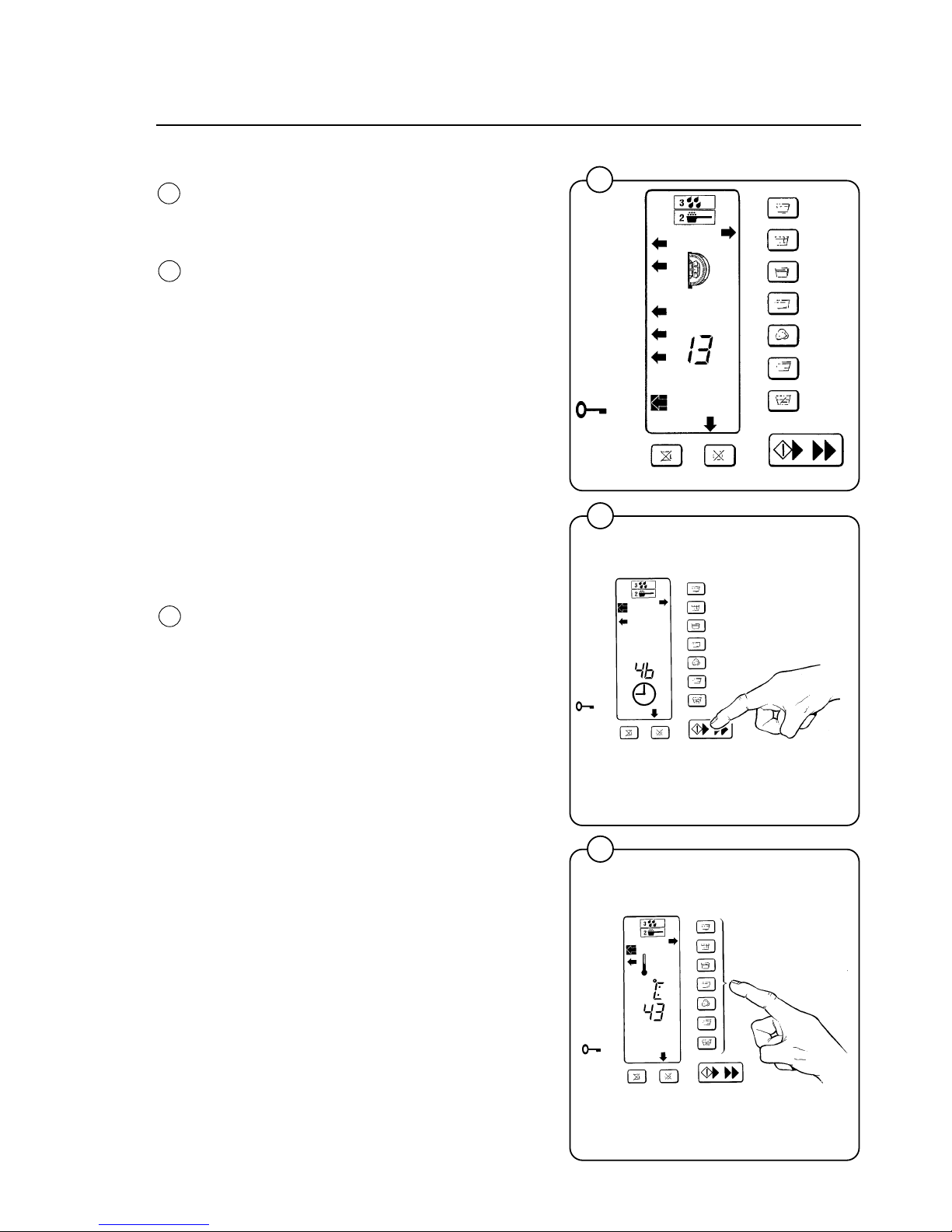
17
1303
1022
1020
Operating Instructions
Insert required number of quarters as shown
on the display, which counts down quarters as
they are inserted. Press START button when
the display shows 00.
A clock symbol will now appear and remaining
wash time in minutes counts down. (The time for
each cycle will not be displayed until the cycle
has been run once completely from beginning to
end, so the microprocessor knows how long it
should take). The microprocessor retains in
memory how long it took to run each cycle the
last five times and displays the average time.
Since water pressure may fluctuate affecting fill
times, the displayed average cycle time is not
always exact and may vary from machine to
machine. If you find cycle times taking longer and
longer, use that information as a warning that
your water inlet screens may be clogged,
extending fill times, or some other problem may
exist.
Figure 31 illustrates a temperature display
function only available on washers with built-in
heating, which are not used in North America.
Fig.
29
Fig.
30
Fig.
31
31
30
29
Page 22
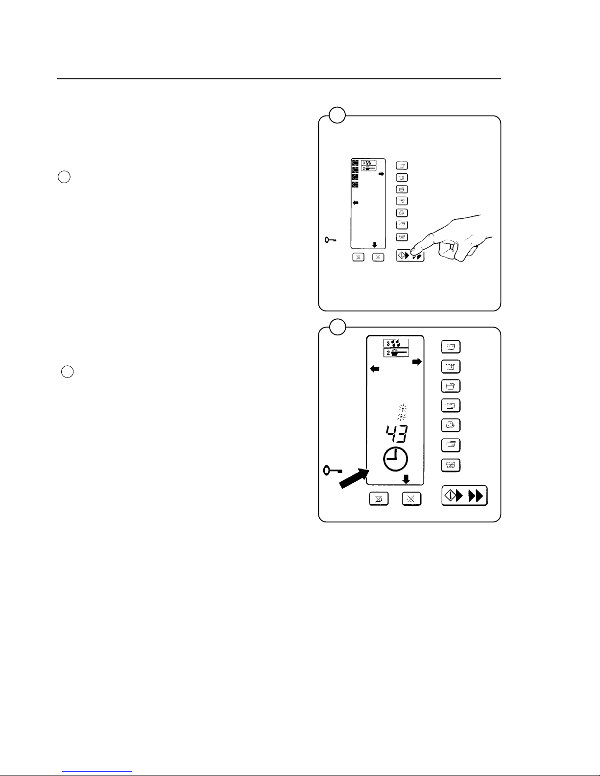
18
1304
1024
Operating Instructions
Fig.
33
Rapid Advance
Within 5 minutes after starting (only while the
colon : is flashing), steps of the wash cycle can
be skipped by using Rapid Advance.
• Press and hold down the START button until
the arrows rapid advance. Stop pressing
where you want the cycle to continue.
• If during the first five minutes of a cycle a
customer realizes they put a wrong item of
clothing in the washer (for example a brightly
colored shirt mixed up with white sheets), you
can rapid advance through the entire cycle,
open the door and remove the item, then lock
the door and press START again to continue
the cycle from where you began rapid
advance. No money is lost and no extra time
is gained. The remaining time will not be
displayed.
Changing Wash Programs While Washing
If within 5 minutes after starting a cycle (only
while the colon : is flashing) a customer realizes
the wrong cycle has been selected, they can
push the START button once briefly to put the
washer on pause. They may then press a
different wash cycle button and press START
again to continue from the same step in the new
cycle.
If the customer selects a different cycle or Extra
Extract option that costs more money, the
washer will not start again unless additional coins
are inserted as shown on the Information
Display. There is no way for a customer to pay
for a less expensive program and switch to a
more expensive program without paying for it, or
to gain additional free wash time.
Note: Rapid Advance is only possible during the
first five minutes of a cycle, while the colon : is
flashing. However, if the START button is
pressed after five minutes has elapsed it will put
the wash cycle on pause, which means washing
stops, the clock stops counting down remaining
wash time, and an arrow flashes on the
Information Display at which ever step the wash
cycle was in when pause began. Press START
again to resume washing. Be alert to any
accidental pauses, which are unlikely but
possible.
Fig.
32
33
32
Page 23
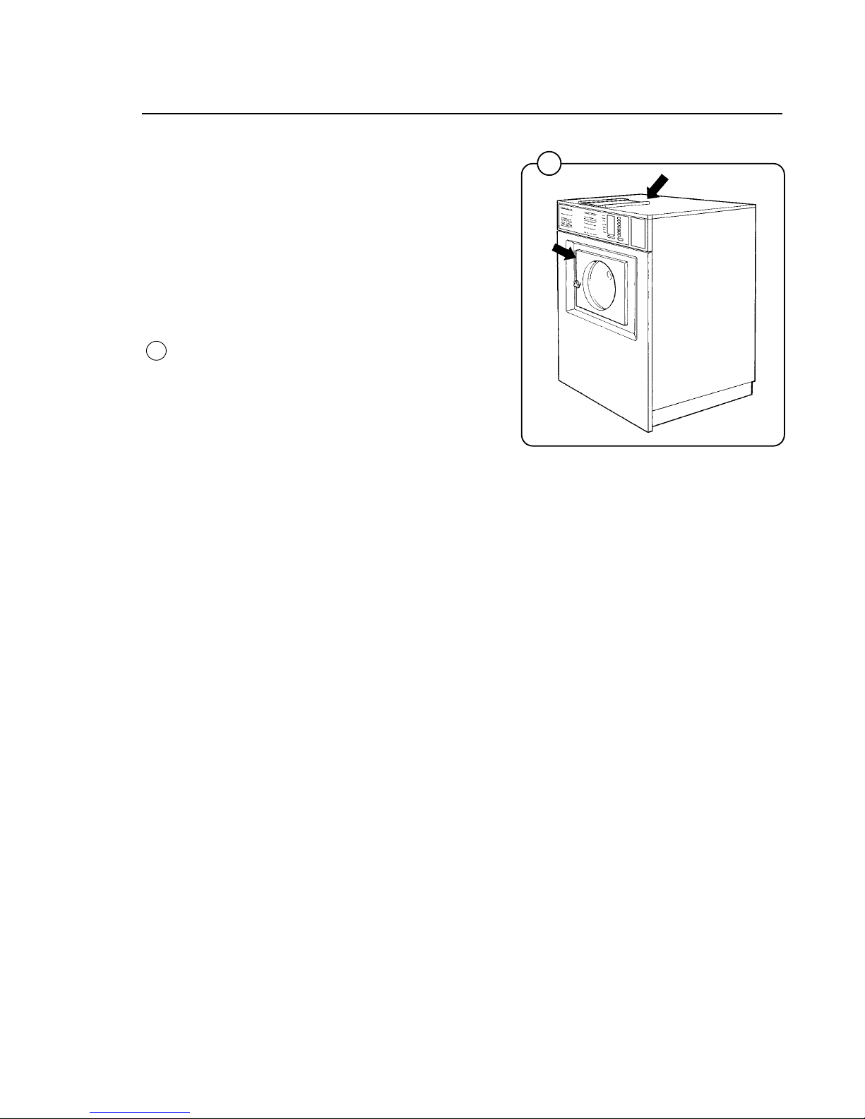
19
Fig.
34
Maintenance
This machine has been carefully designed to
minimize preventative maintenance. However,
the following routine service operations should
be performed at regular intervals (depending on
how much the machine is used).
Daily
• Clean detergent residue from the door seal
and check that the door does not leak.
• Clean the detergent compartments and wipe
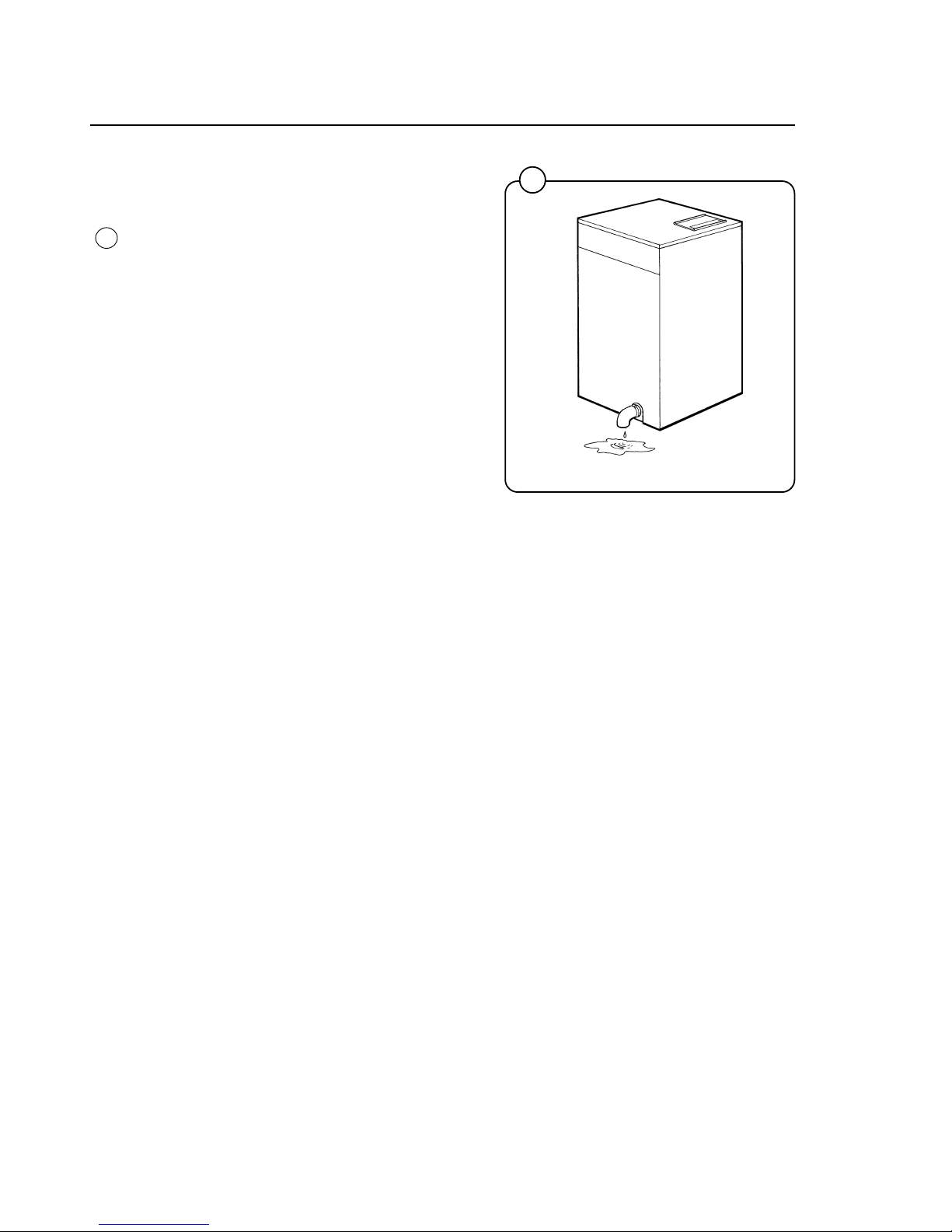
down the machine with a damp cloth.
• Check that the drain valve does not leak.
• Start the machine and check that the door is
locked while the machine is operating.
Operating Instructions
1584
34
Page 24
20
Fig.
35
Every three months
• Check for leaks in valves, hoses and connections.
• Remove any lint from the machine’s drainage
system.
Troubleshooting
If the machine won’t start, check that:
• the circuit breaker is on.
• the manual shut-off valves for water are open.
• a program has been selected.
• the door is properly locked.
0382
Maintenance
35
Page 25
21
Fig.
36
Fault-finding Program
If there is a power failure the washer will
remember the selected cycle for about 8 -10
minutes. The cycle will restart automatically when
power is restored.
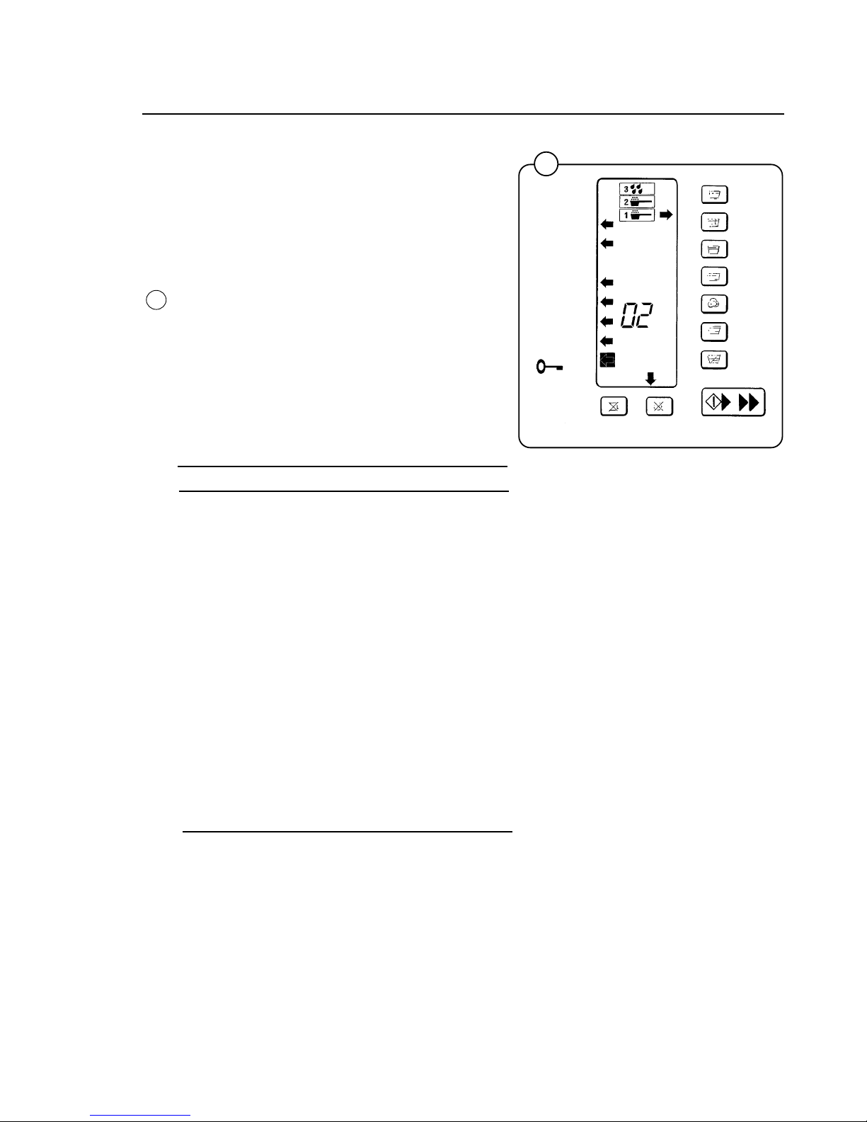
Certain faults are automatically detected and
indicated by a number code shown in the
Information Display .
For fault codes 01 and 02 restart may be
attempted after the fault has been corrected. For
all other faults power to the washer must be
turned off and on again before the washer can be
restarted.
If fault codes 03-09 appear, contact authorized
service personnel.
Fault Code Cause of fault
01 Water level too low. Open water
taps. Check level control.
Check drain valve for leak.
02 Door lock fault. Open and lock
door again. Replace if necessary.
03 Break in or to temperature sensor.
04 Short-circuit in or to temperature
sensor.
05 Water in drum at start of cycle.
Clogged drain valve or drain line.
06 Software error. Try again or call
Wascomat.
07 Not used.
08 Too much water in drum at start of
an extraction. Clogged drain valve
or drain line.
09 Not used.
1026
Fault-Finding Program
36
Page 26
22
Built-in service program
1476
1037
38
37
ON/OFF
Fig.
37
Fig.
38
Built-in service program
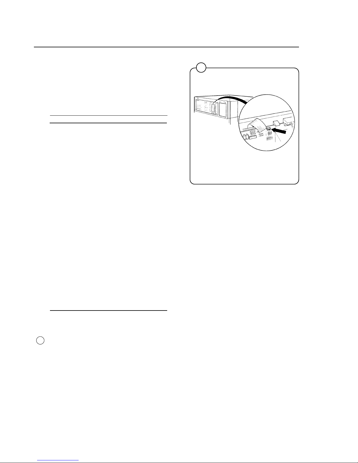
A service program has been built into the
washer. This program should only be used by
qualified service personnel.
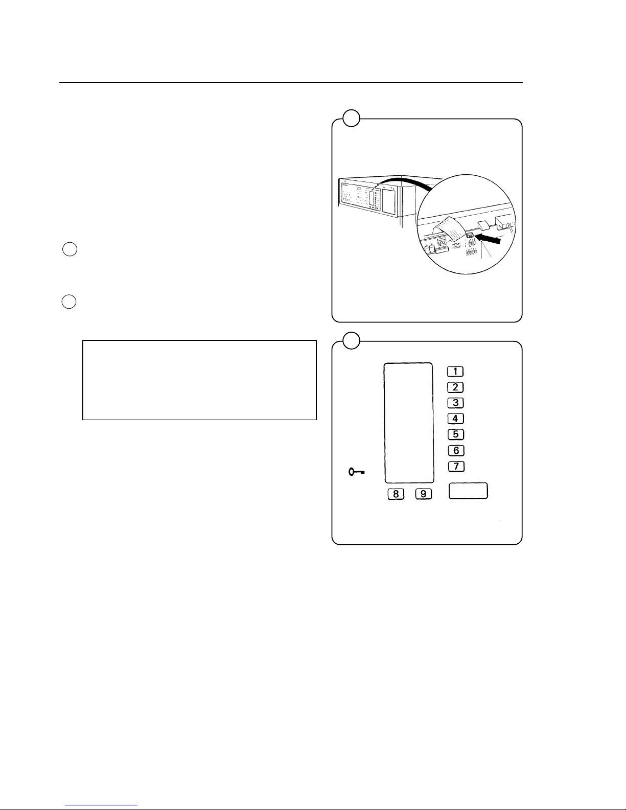
Setting service switch
• Remove the washer top cover.
• Move the service switch to the service
program position. (The switch is located on
top of the circuit board next to the ribbon
connector).
This transforms the buttons into a numerical
keypad. Numbers 1-7 are on the wash cycle
buttons, the Extra Extract button is 8 and the
Gentle Wash button is 9. The START button
serves as an ON/OFF switch.
NOTE:
When in service program the number 0
does not exist. Numbers used are 11-19,
21-28 etc.
Page 27
23
Built-in service program
1038
39
Fig.
39
Function checks
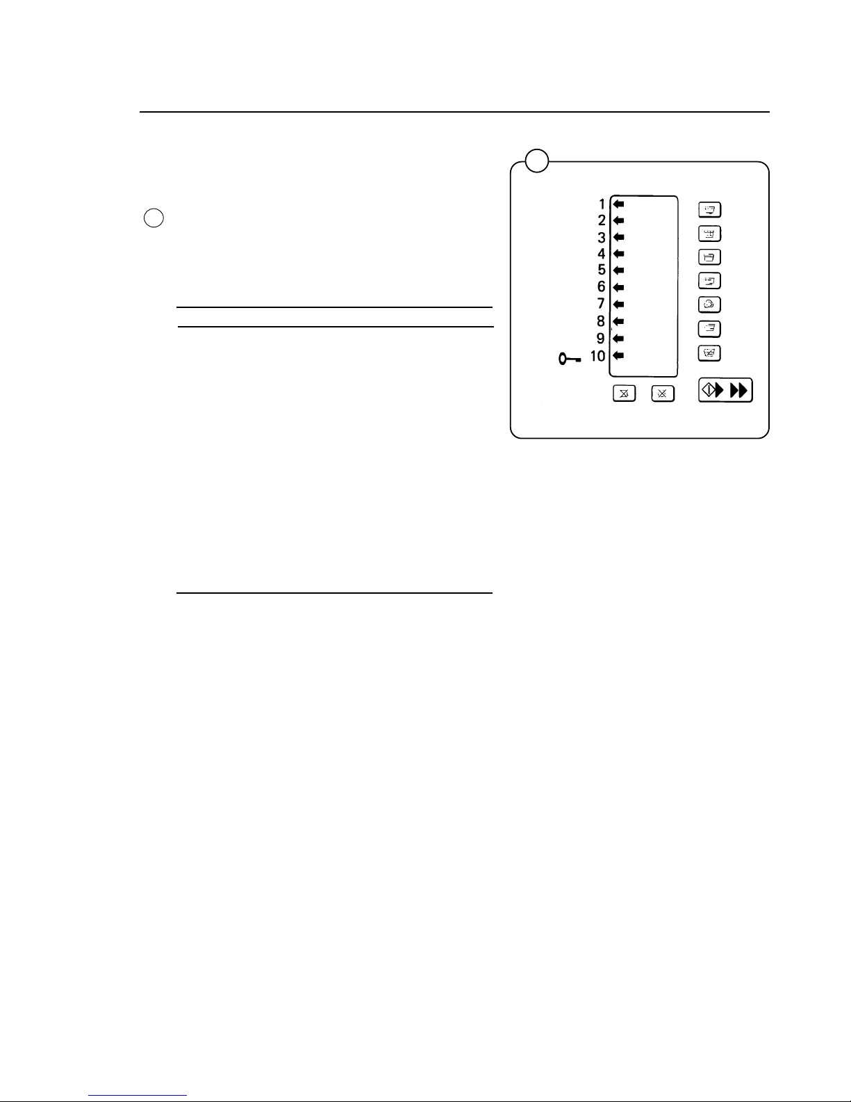
Arrows indicate certain inputs by lighting. For
example, arrow number 5 is lit when the door
closes. This shows that the door lock microswitch
is operating correctly.
The table below shows the inputs displayed by
the arrows.
Arrow Function
1 Price programming switch
2 Coin meter input
3 Not used
4 Not used
5 Door lock switch
6 Price reduction
7 Not used
8 Free wash
9 Not used
10 ON/OFF (Use START button).
(Arrows not presently used are being reserved
for future software enhancements).
Page 28
24
Built-in service program
1476
40
It is also possible to directly activate certain
functions by using the buttons on the keypad.
The chosen function can then be turned on and
off using the START button. Arrow 10 (see Fig.
39) simply shows if the function is on or off.
This table shows which functions can be
activated, along with the number code for each.
Code Function
11 Flush compartment 1 (only W185ES)
12 Flush compartment 2
13 Flush compartment 3
14 Not used
15 Not used
16 Hot water valve
17 Cold water valve (only W185ES)
Flush compartment 1
(only W75ES, W105ES, W125ES)
18 Not used
19 Not used
21 Motor (clockwise)
22 Motor (counter-clockwise)
23 Not used
24 Extraction (counter-clockwise)
25 Not used
26 Drain valve
27 Door lock
28 Not used
Leaving service program
• Return the service switch to its original
position.
• Refit the machine’s top cover.
Fig.
40
Page 29
25
Programming
1473
1030
42
41
Coin-operated machines
The prices of the various wash cycles must be
programmed into the microprocessor. On
EMERALD SERIES washers you can program
different prices for the seven cycles!
You can also program the prices to drop by any
percentage between any hours of any days,
automatically!
Price programming
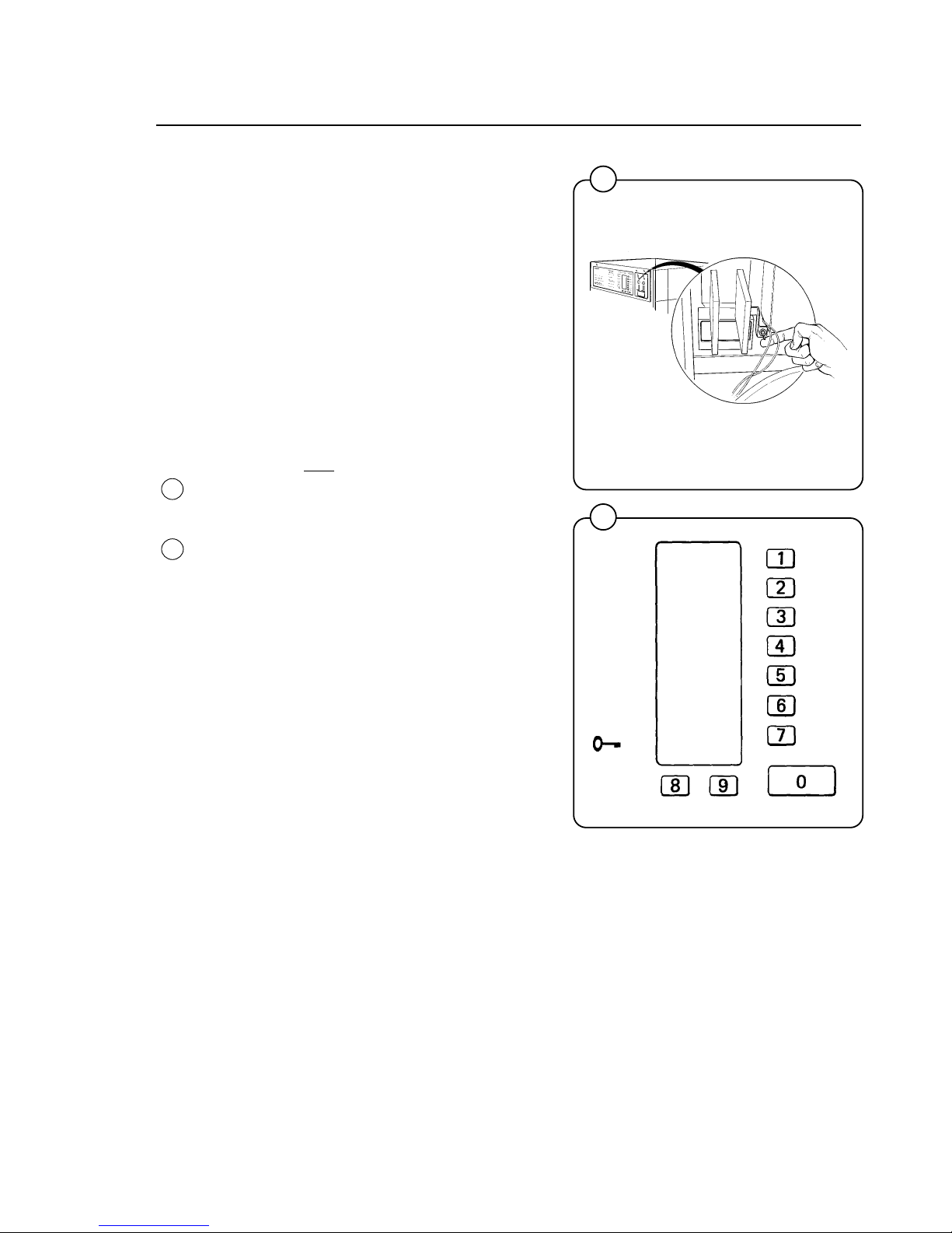
• Remove the coin box.
• Press one wash cycle button so an arrow
points to it.
• Toggle and
hold the price programming switch
located at the back of the coin box in the PP
(price programming) position.
This transforms the various buttons into a
numerical keypad. Numbers 1 - 7 are on the
wash cycle buttons, the Extra Extract button is
8, and the Gentle Wash button is 9. The
START button is 0.
Fig.
41
Fig.
42
Page 30
26
Programming
1031
Fig.
43
43
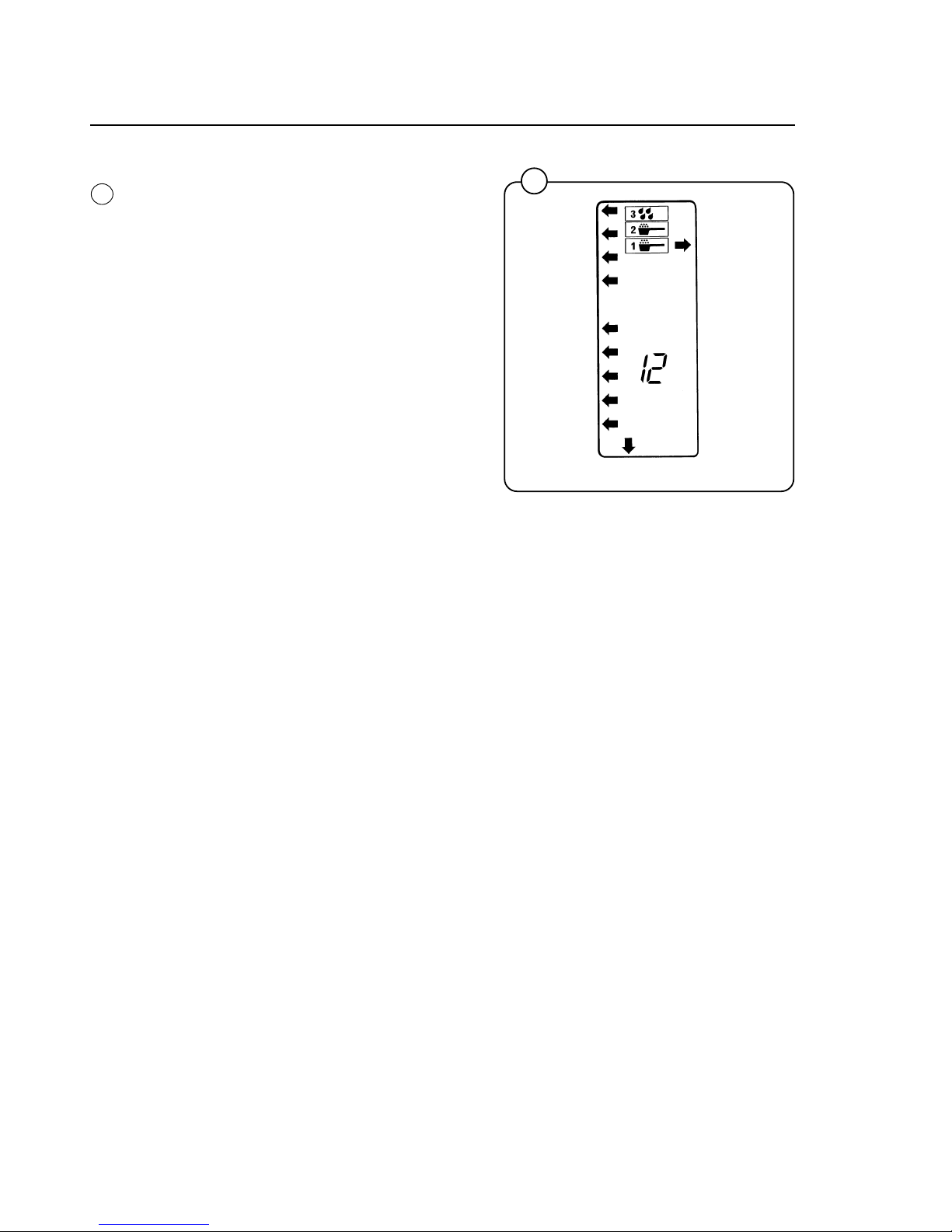
• Program the price by using the keypad to
enter the number of quarters needed to start
the selected wash cycle. For example, press
"1" and "2" to enter 12 quarters for a $3.00
vend price.
• Release the price programming switch. Price
programming of one wash cycle is now
complete. Repeat for the other six cycles,
using any prices in quarters you want.
If you want to raise prices if Extra Extract is also
selected, first program prices for each of the
seven wash cycles. Then program a different
price for each wash cycle plus Extra Extract. For
example, program a price for the Hot cycle. Then
press the Hot button
and
the Extra Extract button
so arrows point to both. Now program a new
price for the combination of Hot plus Extra
Extract. Typically you would program a price for
the combination that is one quarter higher, but
that's totally up to you. If you later change pricing
of a cycle don't forget to change pricing of the
combination with Extra Extract.
Use of the Gentle Wash button cannot affect
pricing.
Programming Tip:
Too many different prices may confuse
customers. We suggest using three or four
different prices for the seven wash cycles.
Typically Heavy Soil will be the most expensive,
Hot and Warm the second most expensive,
Quick-Wash, Delicate, and Permanent Press the
third most expensive, and Cold least of all. But as
always, pricing is totally up to
you
. Wascomat
EMERALD SERIES washers give you complete
price flexibility so you can maximize revenue and
beat the competition.
Page 31
27
Programming
1838
1033
1473
1030
47
46
45
44
Fig.
44
Wiring for automatic price reduction
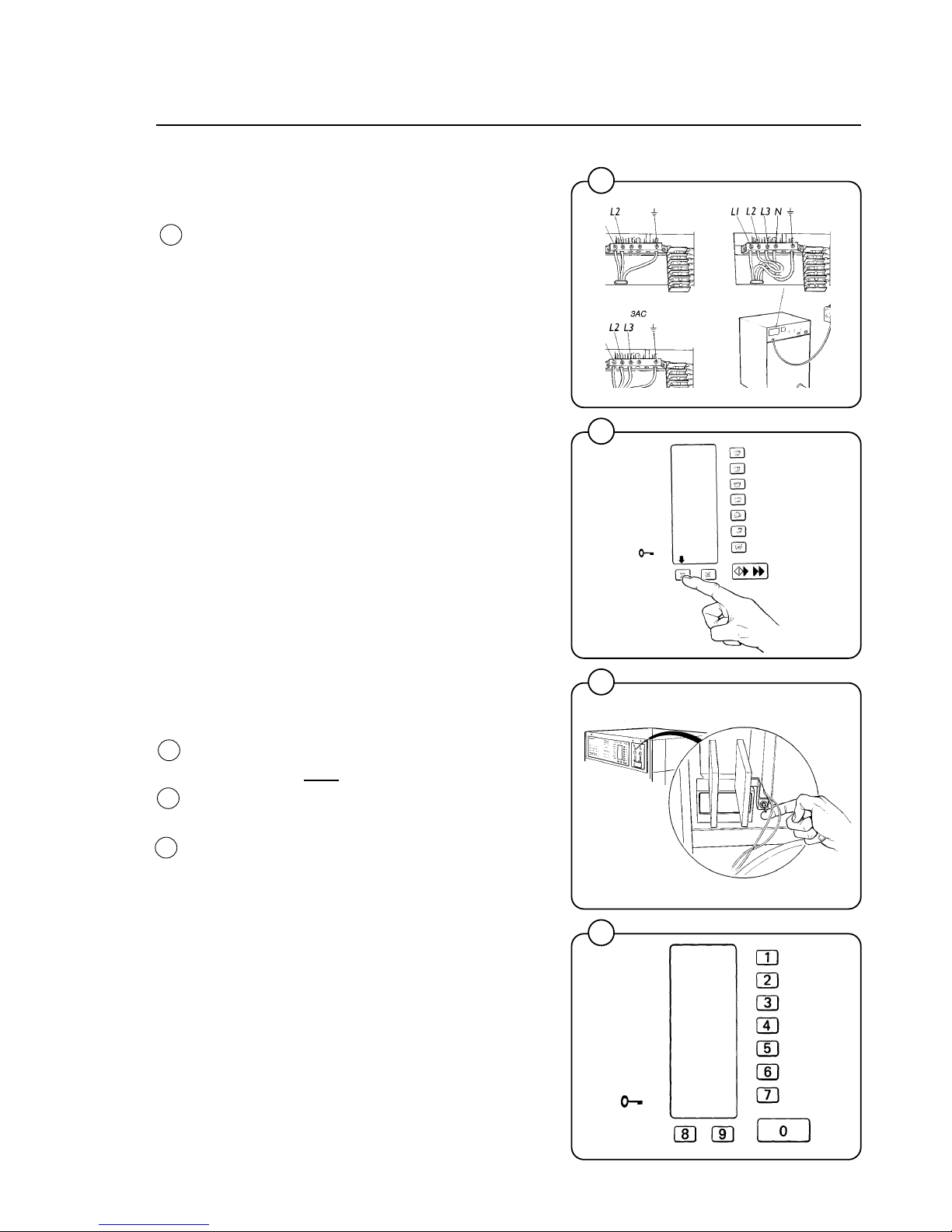
Emerald washers have a price reduction terminal
block located next to the main power terminal
block. Your installer must run a pair of wires from
each washer terminal block to Wascomat's
automatic price reduction relay box (Part No.
098887), which can control 16 washers. Each
relay box can be expanded to handle up to 32
washers by adding snap-in contacts (Part No.
510192). The relay box is plugged into a
programmable appliance timer clock (such as
Radio Shack model 63-892) which you program
with the days and hours you want automatic price
reduction to be on or off. Refer to technical
instruction No. 1040 for detailed installation
instructions.
Programming automatic price reduction
Price reduction is programmed into each
individual
washer as a percentage reduction of
the normal prices. For example, if a cycle is
normally eight quarters and you program a 25%
price reduction, the reduced price will be 6
quarters. An external clock is programmed with
the days and hours you want the price reduction
to activate and deactivate. (This clock has
nothing to do with the clock symbol on the
Information Display, which counts down
remaining wash time).
• Press the Extra Extract button until
only
the
arrow that points to it is lit.
• Toggle and
hold the price programming switch
at the back of the money box compartment.
This transforms the buttons into a numerical
keypad. Numbers 1-7 are on the wash cycle
buttons, the Extra Extract button is 8 and the
Gentle Wash button is 9. The START button
is 0.
Fig.
47
Fig.
46
Fig.
45
L1
L1
Page 32
28
Programming
1046
1474
1475
50
49
48
• Enter the desired percentage reduction using
two numbers (for example, enter 2 and 5 for
25% reduction). If you make a mistake just
press the START button (0) to clear the data.
Prices will round up to the nearest quarter
when price reduction is active.
• Release the price programming switch. Programming is now complete. Check to see that
your regular prices appear on the display
after
you select a cycle. If not, just toggle the
programming switch once to reset the system.
Since price reductions are programmed into each
individual washer you can program different
percentage price reductions for different size
washers, or you could connect your various size
washers to separate clocks and program the
clocks to reduce prices on different days or at
different times. With Wascomat Emerald Series
washers there is virtually no limit on your ability to
create innovative price promotions to build your
business, maximize profits, and eliminate any
correlation between water consumption and
revenue!
Coin counter
The microprocessor features a built-in coin
counter which uses a four-digit number (0000 -
9999) to indicate how many coins have been fed
into the meter. The coin counter can only be reset
to zero with a special microchip from Wascomat,
so if someone else does your connections, you
can check the reciepts.
A coin count reading is made as follows:
• Press one of the cycle selection buttons
repeatedly until the
only
arrow lit is the bottom
left arrow (open door arrow).
• Toggle and
hold the price programming
switch.
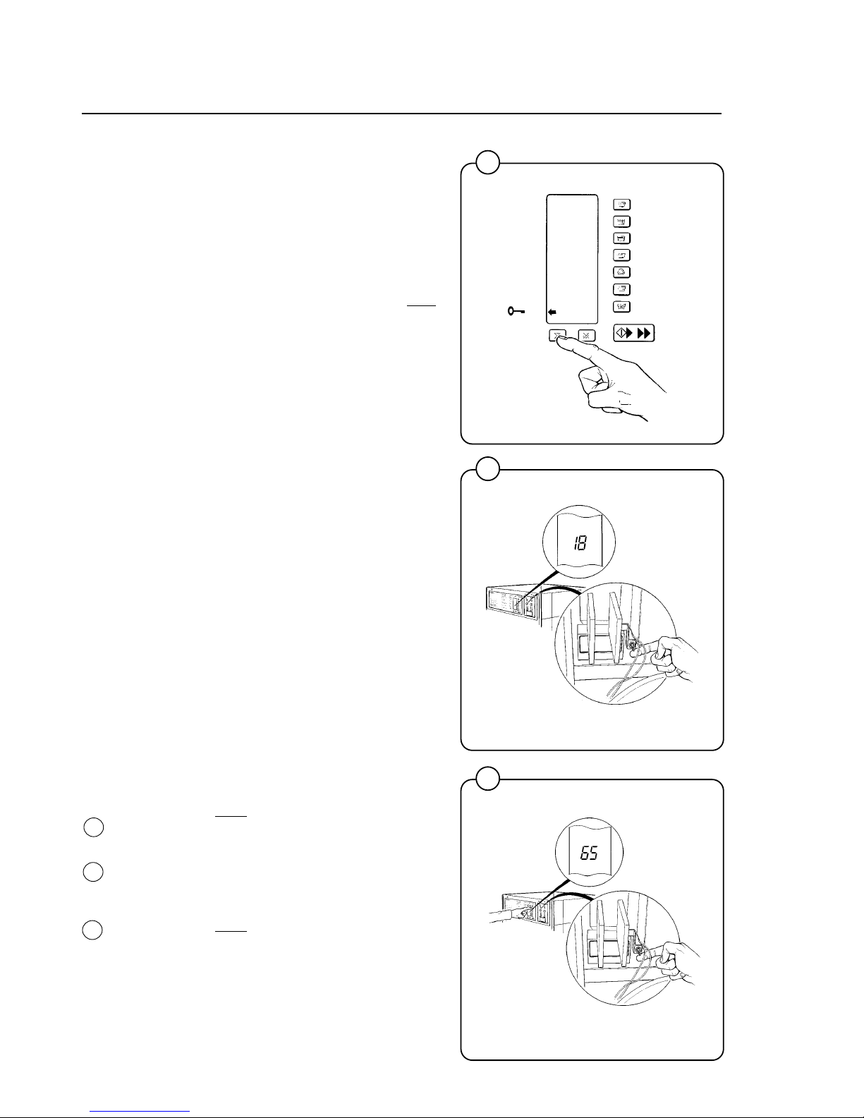
• The two lower digits (for example "18") of the
four-digit coin count number (for example
6,518) will now appear in the Information
Display. Release the programming switch.
• Toggle and
hold the price programming switch
while
also
pressing any one of the wash cycle
buttons. The two higher digits (for example,
"65") of the coin count number will now appear.
A total of 6,518 quarters have been inserted
into this washer. If your log book shows the
count was 6,200 last time you collected, then
6,518 minus 6,200 equals 318 quarters, which
should be in the money box!
Fig.
48
Fig.
50
Fig.
49
Page 33
29
Wash Cycles
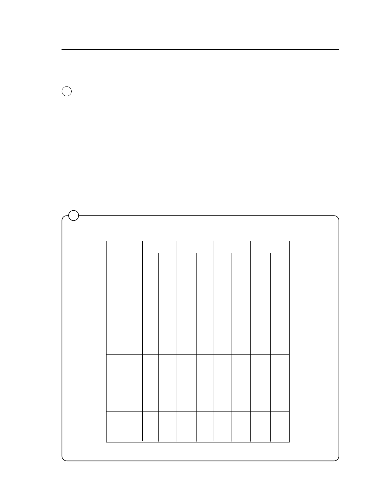
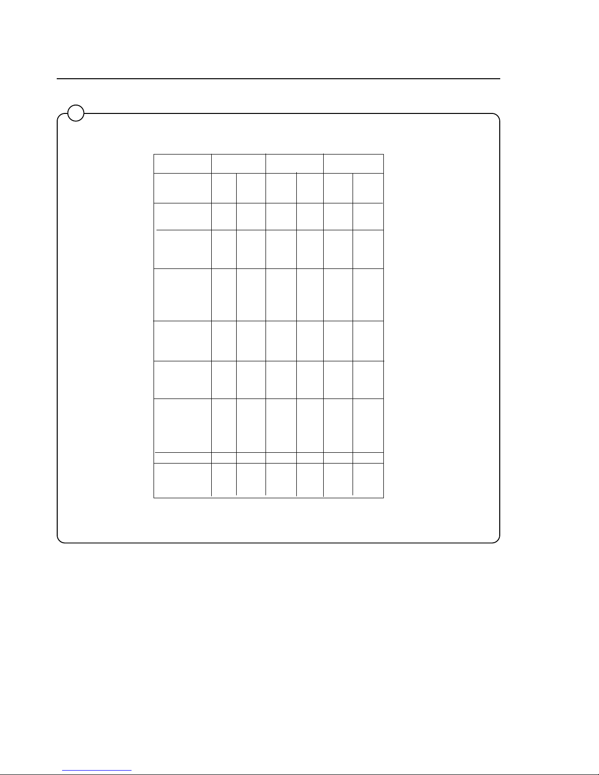
In the figure below is an overview of the seven wash cycles.
On the following pages you will find a more detailed description of the
cycles.
Wash Cycles
51
1202
Fig.
51
HOT WARM COLD PERM PRESS
Time Temp. Time Temp. Time Temp. Time Temp.
(Min.) (Min.) (Min.) (Min.)
Prewash 3 Warm 3 Warm 3 Cold 3 Warm
Detergent 1
Drain 0.8 0.8 0.8 0.8
Mainwash 6 Hot 6 Warm 6 Cold 6 Warm
Detergent 2
Drain 0.8 0.8 0.8 0.8
Extraction 0.5 0.5 0.5 0.5
Rinse 1 1 Warm 1 Cold 1 Cold 1 Cold
Drain 0.8 0.8 0.8 0.8
Extraction 0.5 0.5 0.5 0.5
Rinse 2 1 Cold 1 Cold 1 Cold 1 Cold
Drain 0.8 0.8 0.8 0.8
Extraction 0.5 0.5 0.5 0.5
Rinse 3 2 Cold 2 Cold 2 Cold 2 Cold
Detergent 3
Drain 1 1 1 1
Extraction 4 4 4 1
Shake-out 0.5 0.5 0.5 0.5
Total time 23 23 23 20
(water fill time
not included)
Page 34
30
51
Wash Cycles
1202
DELICATE QUICK-WASH HEAVY SOIL
Time Temp. Time Temp. Time Temp.
(Min.) (Min.) (Min.)
Prewash 2 Cold
Drain 0.8
Prewash 3 Warm
Detergent 1
Drain 0.8
Mainwash 4 Warm 5 Warm 8 Hot
Detergent 2
Drain 0.8 0.8 0.8
Extraction 0.5 0.5 0.5
Rinse 1 1 Cold 1 Cold 1 Warm
Drain 0.8 0.8 0.8
Extraction 0.5
Rinse 2 1 Cold 1 Cold 1 Cold
Drain 0.8 0.8 0.8
Extraction 0.5
Rinse 3 2 Cold 2 Cold 2 Cold
Detergent 3
Drain 1 1 1
Extraction 1 3 4
Shake-out 0.5 0.5 0.5
Total time 13.3 16.3 27.6
(water fill time
not included)
Page 35
31
Wash Cycles
52
1203
Hot
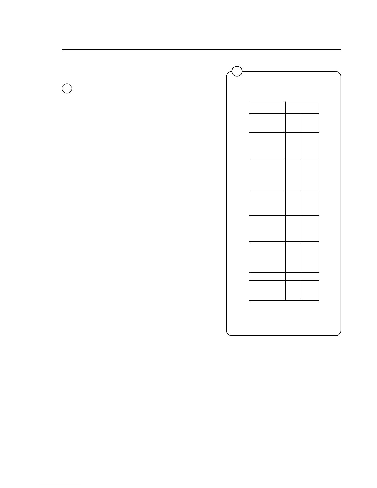
After the machine has started and the door
automatically locked, the drain valve will close
and the hot and cold water valves will open to fill
the machine with mixed hot and cold water to the
level determined by the level control. At the same
time detergent from compartment 1 is mixed with
the incoming water.
When this level is reached, both water valves will
close. During filling and then through the wash
program the drum has a reversing rotation.
At the end of the prewash, the drain valve will
open, whereafter hot water will fill to the level
determined by the level control. At the same time
detergent from compartment 2 is mixed with the
incoming hot water.
The water level controlled machine will now wash
the fabrics for 6 minutes. The machine is then
emptied.
Hot and cold water are filled to the medium level
for the first rinse which lasts one minute, followed
by spin extraction for 30 seconds. After the
extraction comes the second rinse in cold water,
ending with extraction, whereafter the third rinse
is started. Fabric softener is automatically
admitted during the third rinse. The fabrics are
rinsed in cold water for two minutes followed by a
extraction of four minutes duration. Finally there
is a shake out for half a minute.
Fig.
52
HOT
Time Temp.
(Min.)
Prewash 3 Warm
Detergent 1
Drain 0.8
Mainwash 6 Hot
Detergent 2
Drain 0.8
Extraction 0.5
Rinse 1 1 Warm
Drain 0.8
Extraction 0.5
Rinse 2 1 Cold
Drain 0.8
Extraction 0.5
Rinse 3 2 Cold
Detergent 3
Drain 1
Extraction 4
Shake-out 0.5
Total time 23
(water fill time
not included)
Page 36
32
Warm
On starting the machine, the door will automatically be locked, and the pre-wash carried out as
previously described, whereafter the main wash
is started.
As the main wash is started, the drain valve
closes, detergent is admitted and mixed hot and
cold water is filled to the level determined by the
level control.
On reaching this level, the water valves are
closed.
The water level controlled machine will now wash
the fabrics for six minutes. The machine is then
emptied.
Cold water is filled for the first rinse which lasts
one minute, followed by extraction for 30
seconds.
After this extraction comes the second rinse in
cold water ending with extraction, whereafter the
third rinse is started. Fabric softener is
automatically admitted during the third rinse. The
fabrics are rinsed with cold water for two minutes
followed by a extraction of four minutes duration.
Finally there is a shake out for half a minute.
Wash Cycles
53
1204
Fig.
53
WARM
Time Temp.
(Min.)
Prewash 3 Warm
Detergent 1
Drain 0.8
Mainwash 6 Warm
Detergent 2
Drain 0.8
Extraction 0.5
Rinse 1 1 Cold
Drain 0.8
Extraction 0.5
Rinse 2 1 Cold
Drain 0.8
Extraction 0.5
Rinse 3 2 Cold
Detergent 3
Drain 1
Extraction 4
Shake-out 0.5
Total time 23
(water fill time
not included)
Page 37
33
Wash Cycles
54
1205
Cold
On starting the machine, the door will automatically be locked, the drain valve closed, the cold
water valve opened and the pre-wash carried out
as previously described, whereafter the main
wash is started.
As the main wash is started, the drain valve
closes, detergent is admitted and cold water is
filled to the level determined by the level control.
On reaching this level, cold water is closed.
The water level controlled machine will now wash
the fabrics for six minutes. The machine is then
emptied.
Cold water is filled for the first rinse which lasts
one minute, followed by extraction for 30
seconds.
After this extraction comes the second rinse in
cold water concluded with extraction, whereafter
the third rinse is started.
Fabric softener is automatically admitted during
the third rinse. The fabrics are rinsed with cold
water for two minutes followed by a extraction of
four minutes duration. Finally there is a shake out
for half a minute.
Fig.
54
COLD
Time Temp.
(Min.)
Prewash 3 Cold
Detergent 1
Drain 0.8
Mainwash 6 Cold
Detergent 2
Drain 0.8
Extraction 0.5
Rinse 1 1 Cold
Drain 0.8
Extraction 0.5
Rinse 2 1 Cold
Drain 0.8
Extraction 0.5
Rinse 3 2 Cold
Detergent 3
Drain 1
Extraction 4
Shake-out 0.5
Total time 23
(water fill time
not included)
Page 38
34
Permanent Press
On starting the machine, the door will automatically be locked, the drain valve closed, the hot and
cold water valves opened and the pre-wash will
be carried out as previously described, whereafter the main wash is started.
As the main wash is started, the drain valve
closes, detergent is admitted and mixed hot and
cold water is filled to the level determined by the
level control.
On reaching this level, the water valves are
closed and the wash motor starts its reversing
rotation.
The water level controlled machine will now wash
the fabrics for six minutes. The machine is then
emptied.
Cold water is filled for the first rinse which lasts
one minute, followed by extraction for 30
seconds.
Fabric softener is automatically admitted during
the third rinse. The fabrics are rinsed with cold
water for two minutes followed by a extraction of
one minute duration. Finally there is a shake out
for half a minute.
Wash Cycles
55
1206
Fig.
55
PERM PRESS
Time Temp.
(Min.)
Prewash 3 Warm
Detergent 1
Drain 0.8
Mainwash 6 Warm
Detergent 2
Drain 0.8
Extraction 0.5
Rinse 1 1 Cold
Drain 0.8
Extraction 0.5
Rinse 2 1 Cold
Drain 0.8
Extraction 0.5
Rinse 3 2 Cold
Detergent 3
Drain 1
Extraction 1
Shake-out 0.5
Total time 20
(water fill time
not included)
Page 39
35
Delicate
On starting the machine, the door will automatically be locked.
As the main wash is started, the drain valve
closes, detergent is admitted and mixed hot and
cold water is filled to the level determined by the
level control.
On reaching this level, the water valves are
closed.
The water level controlled machine will now wash
the fabrics for four minutes. The machine is then
emptied.
Cold water is filled for the first rinse which lasts
one minute.
Than comes the second rinse in cold water
whereafter the third rinse is started. Fabric softener is automatically admitted during the third
rinse. The fabrics are rinsed with cold water for
two minutes followed by a extraction of one
minute duration. Finally there is a shake out for
half a minute.
During washing and rinsing gentle action is used,
which is 3 seconds drum rotation and 12 seconds
pause, then reverse direction and repeat. The
GENTLE WASH option button does not affect the
Delicate cycle.
Wash Cycles
56
Fig.
56
DELICATE
Time Temp.
(Min.)
Prewash
Drain
Prewash
Detergent 1
Drain
Mainwash 4 Warm
Detergent 2
Drain 0.8
Extraction 0.5
Rinse 1 1 Cold
Drain 0.8
Extraction
Rinse 2 1 Cold
Drain 0.8
Extraction
Rinse 3 2 Cold
Detergent 3
Drain 1
Extraction 1
Shake-out 0.5
Total time 13.3
(water fill time
not included)
Page 40
36
Wash Cycles
57
Quick-Wash
On starting the machine, the door will automatically be locked, the drain valve closed.
As the main wash is started, the drain valve
closes, detergent is admitted and warm water is
filled to the level determined by the level control.
On reaching this level, hot water is closed.
The water level controlled machine will now wash
the fabrics for five minutes. The machine is then
emptied.
Cold water is filled for the first rinse which lasts
one minute.
Then comes the second rinse in cold water,
whereafter the third rinse is started.
Fabric softener is automatically admitted during
the third rinse. The fabrics are rinsed with cold
water for two minutes followed by a extraction of
three minutes duration. Finally there is a shake
out for half a minute.
Fig.
57
QUICK-WASH
Time Temp.
(Min.)
Prewash
Drain
Prewash
Detergent 1
Drain
Mainwash 5 Warm
Detergent 2
Drain 0.8
Extraction 0.5
Rinse 1 1 Cold
Drain 0.8
Extraction
Rinse 2 1 Cold
Drain 0.8
Extraction
Rinse 3 2 Cold
Detergent 3
Drain 1
Extraction 3
Shake-out 0.5
Total time 16.3
(water fill time
not included)
Page 41
37
Heavy Soil
On starting the machine, the door will automatically be locked, the drain valve closed, the hot and
cold water valves opened and the two pre-washes will be carried out as previously described,
whereafter the main wash is started.
As the main wash is started, the drain valve
closes, detergent is admitted and hot is filled to
the level determined by the level control.
On reaching this level, the water valve is closed
and the wash motor starts its reversing rotation.
The water level controlled machine will now wash
the fabrics for eight minutes. The machine is then
emptied.
Hot and cold water are filled for the first rinse
which lasts one minute, followed by extraction for
30 seconds.
Fabric softener is automatically admitted during
the third rinse. The fabrics are rinsed with cold
water for two minutes followed by a extraction of
four minutes duration. Finally there is a shake out
for half a minute.
OPTION BUTTONS:
EXTRA EXTRACT -- Selecting this option adds 4
minutes to the final extraction of any cycle. For
example, the HOT cycle plus EXTRA EXTRACT
gives the customer a total of 8 minutes
extraction. You can easily program the washer to
charge more money (usually one more quarter) if
this option is selected! The effect of extra
extraction depends on the type of laundry washed, load size, etc.
GENTLE WASH -- The normal wash action of a
Wascomat washer is 12 seconds rotation, 3
seconds pause, reverse direction and repeat.
Selecting the GENTLE WASH option converts
the selected wash cycle to gentle action, which is
3 seconds drum rotation and 12 seconds pause,
reverse direction and repeat. The DELICATE
cycle always uses gentle action so it is not
affected by this option. There is no extra charge
to the customer for this option, so it is simply up
to them to choose their preference. You may
want to advertise and promote this option since
market research indicates there are people who
believe certain clothing items are too delicate to
wash in a commercial washer. Now you have the
answer!
Wash Cycles
58
Fig.
58
HEAVY SOIL
Time Temp.
(Min.)
Prewash 2 Cold
Drain 0.8
Prewash 3 Warm
Detergent 1
Drain 0.8
Mainwash 8 Hot
Detergent 2
Drain 0.8
Extraction 0.5
Rinse 1 1 Warm
Drain 0.8
Extraction 0.5
Rinse 2 1 Cold
Drain 0.8
Extraction 0.5
Rinse 3 2 Cold
Detergent 3
Drain 1
Extraction 4
Shake-out 0.5
Total time 27.6
(water fill time
not included)
Page 42
38
Mechanical and electrical design
Machine construction
Outer shell
The outer shell is made of heavy gauge surgical steel and is
attached to a heavy duty, rigid head casting (back gable).
The whole assembly is mounted on a heavy gauge fabricated
steel base, galvanized for long life and corrosion resistance.
Inner cylinder
The inner cylinder is made of perforated surgical stainless steel. It
is equipped with three lifting ribs and has highly-polished side
sheets and back with maximum embossed perforated area to
assure high flow of water and supplies through fabrics.
Scientifically correct ratio of cylinder diameter and depth assures
maximum washing action.
The shaft is electrically welded to the reinforced back of the cylinder. A specially designed chrome-plated sleeve bushing protects
the seals from wear.
1864
59
Fig.
59
Page 43

39
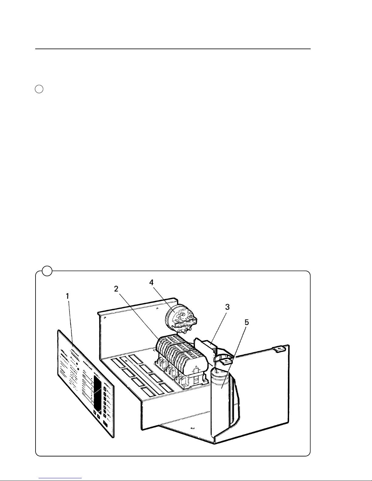
General
The door and the electronic timer with display and program-selection
buttons are fitted at the front of the machine.
All control and indicating components, i.e. relays, level control, etc are
assembled under the top cover, easily accessible from the top of the machine for simplified servicing.
Main units
1 Keypad.
2 Wash cycle buttons.
3 Electronic microprocessor with display .
4 Door - with automatic locking device which remains locked throughout
the different wash processes.
5 Inner cylinder - of stainless steel supported at the rear by two ballraces.
6 Outer drum - of stainless steel (18/8) securely attached to the frame.
7 Wash and extraction motor - for reversing wash action and high speed
spin action.
8 Hot and cold water valves - program and level controlled solenoid valves
for filling with water, and for flushdown of automatic detergent dispenser.
9 Drain valve - the timer controlled valve for draining the machine of water.
10 Siphon breaker - to prevent water in the machine from re-entering the
water supply system.
11 Relays - for wash and extraction.
Fig.
59
Mechanical and electrical design
Page 44
40
Mechanical and electrical design
Control unit
The keypad and microprocessor include all components necessary for
operating the machine such as an Information Display and wash cycle
selection buttons.
The microprocessor (1) is mounted just behind the keypad.
Relays (2), transformer (3) supplying power to the microprocessor, and
level control (4) are located at the top of the machine easily accessible for
service, as are the motor capacitors (5) on 1-phase models.
Electrical connections are made by quick-disconnect plugs.
1865
60
Fig
60
Page 45
41
Mechanical and electrical design
Relays
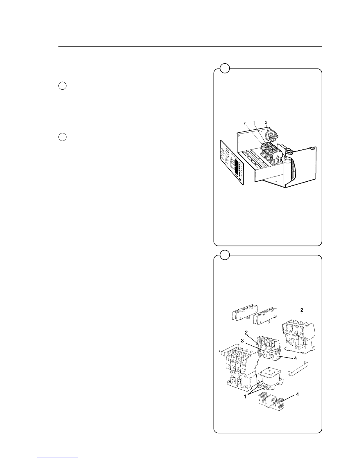
The Wascomat Emerald series models employ
three relays. The relays control:
• the reversing wash of the wash motor (1,2)
• the extraction motor (3)
Construction
The body of the relay holding the stationary
contacts is made of current-resistant plastic. A
solenoid and a contact bank hold the moving
contacts. The contacts are spring-loaded to
assure the correct contact pressure.
The relay is constructed for continous operation,
whether mounted horizontally or vertically.
Screw-type terminals provide perfect connections
even when one or two wires have different diameters.
Operation
When the solenoid is energized, the two halves
of the magnet core are drawn together, pulling
down the moving contacts, thus making or breaking the circuit. When the current cuts out,
springs force the contact bank into its original
position, thus closing or opening the circuits.
Trouble shooting
If the relay fails to operate despite power to the
coil, turn off the power and check the solenoid by
measuring the resistance across the terminals
(1).
If the relay hums when power is applied, this
indicates either a break in the insulator holding
the moving contacts at the axle where it holds the
top half of core (3) or a rusty core (4), which can
be cleaned.
Make sure that the moving contact assembly
moves freely. Always replace burnt or pitted
contacts (2) ... do not reuse contacts.
61
1866
62
0301
Fig.
61
Fig.
62
Page 46
42
63
0473
Mechanical and electrical design
Fig.
63
Panels
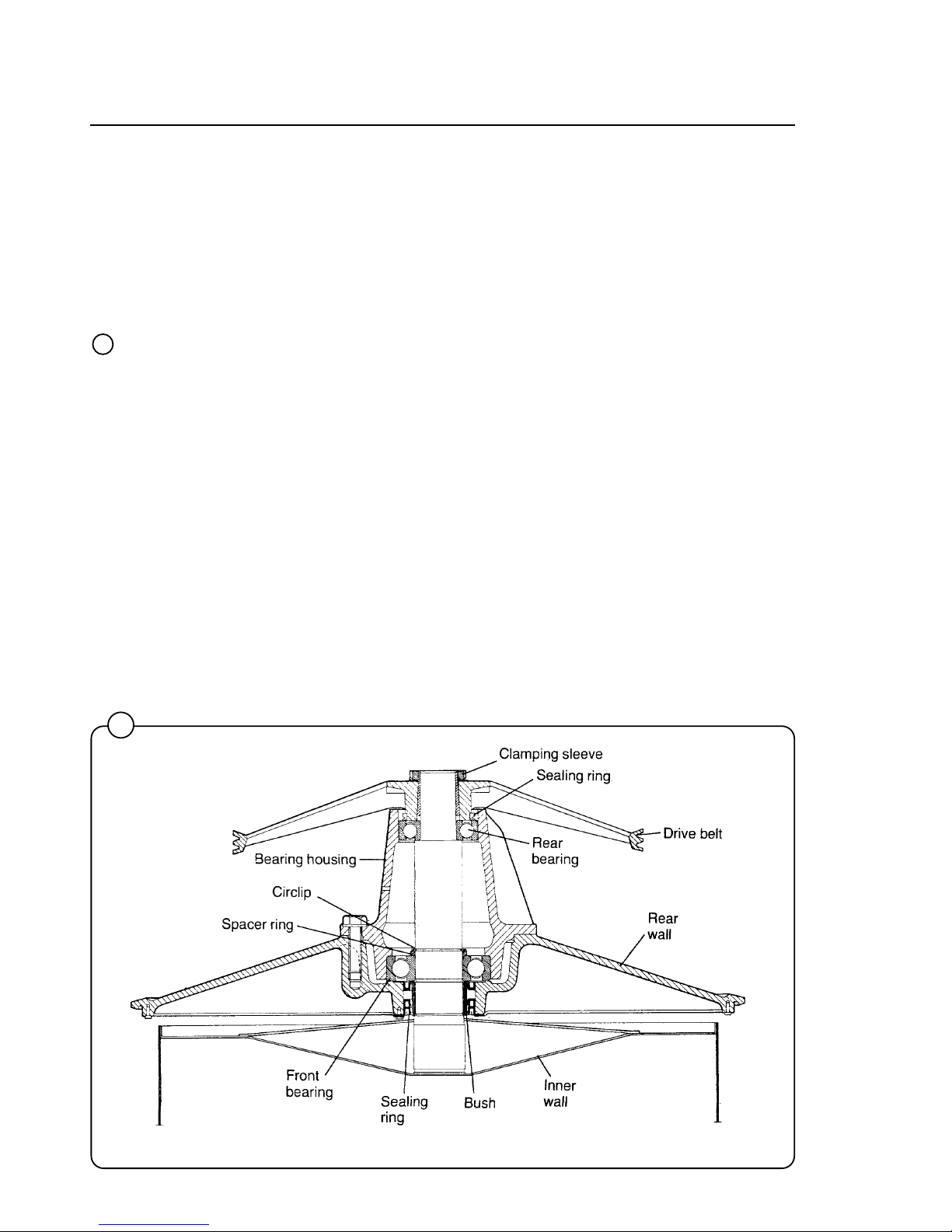
The machines are equipped with a top panel made of stainless steel. The
front panel is available in different colours or in stainless steel. The coloured panels are made of phosphatized steel plate with electrostatically
applied baked enamel paint finish for rust and chip resistance. For servicing
purposes, the panels can easily be removed.
Back gable and bearing
The back gable and the bearing trunnion housing are constructed of a
webbed heavy casting for extra rigidity. The bearings are protected against
imfiltration of water by three neoprene seals. An intermediate safety outlet
provides an escape for any possible condensation.
The seals are mounted on a chrome-plated, noncorrosive, specially hardened sleeve bushing that is mounted on the drive shaft to prevent wear of
the seals and shaft. The main bearing is fitted machinetight into the bearing
trunnion housing. A nut is tightened on the shaft to prevent the cylinder
from moving in and out.
The extension of the bearing trunnion housing supports the rear bearing
holding the shaft. A grease seal is mounted to prevent escape of grease.
The bearings are permanently lubricated and need no maintenance.
Wascomat's design transfers the weight of the loaded wash cylinder to the
largest possible surface area away from the bearings, for longest machine
life.
Page 47
43
Mechanical and electrical design
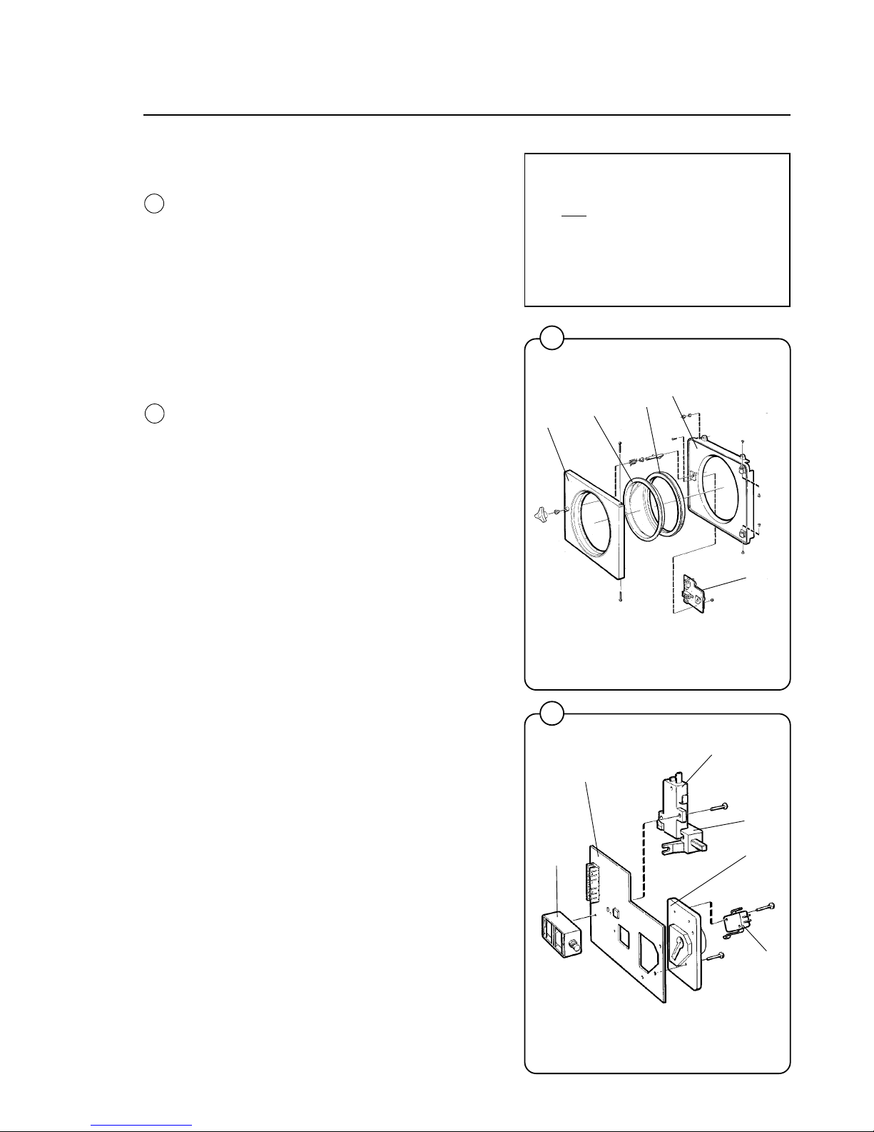
Door, description
The door consists of: backing board (1), door
(2), glass (3) and door gasket (4). The backing
board and door are both made of enameled
aluminium. The backing board is bolted directly
to the outer shell of the washing machine.The
door hinges are fastened on the outside of the
backing board and the door lock (5) on the inside. The heat-hardened glass is mounted in the
door using a special rubber seal which also acts
as a gasket between the door and the washing
machine’s outer shell when the door is closed.
Door lock, description
The door lock consists of a circuit board (1) with
a connector. The following parts are mounted on
the board: the lock plate (2) against which the
locking bolt turns to lock the door and a microswitch (3) which closes when the locking bolt has
locked the door.
There is also a locking device on the circuit card
which acts to lock the locking bolt in place when
the machine starts up. The device consists of a
double-acting drag magnet (4), a delay unit (5)
and the locking device itself (6) which operates
sideways in blocking the locking bolt with a stud.
The locking device can be affected by both the
drag magnet and the delay unit.
The lock operates as follows:
• When the door is shut and the locking bolt
moved to the lock position, the micro switch
will indicate that the door is closed.
• When the machine is started, the drag magnet
actuates the locking device, blocking the door
lock. The locking device signals the delay
unit, closing a switch in the unit. The washing
machine motor will start and water enter the
machine only after the delay unit receives the
information that the door is locked. The bimetallic spring in the delay unit is warmed up
at the beginning of the program.
• Once the washing machine stops at the end of
a cycle, the drag magnet pulls back the
locking stud and allows the door to open. The
delay unit is spring-mounted in the locking
device and is also pulled back by the drag
magnet. The drag magnet operates for about
two minutes to allow the bi-metallic spring to
cool enough not to lock the door again.
• If current should disappear during a cycle, the
delay unit will keep the door locked for about
two minutes, ensuring that the wash water can
drain out (The drain valve opens automatically
when current is lost).
64
65
NOTE
Do not repair a faulty door lock.
Allways replace the old unit
with a new one, to assure proper operation of the door safety
interlock.
1148
1149
5
4
1
2
3
1
5
6
2
3
4
Fig.
64
Fig.
65
Page 48
44
Mechanical and electrical design
66
67
1153
1154
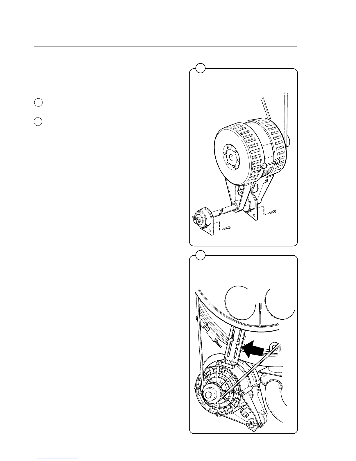
Drive motor
Description in general
The motor is mounted on an axle with rubber
dampeners.
The V-belt is tightened by turning the motor on
the axle and locking it in place using the tightener
on the rear side of the motor. The motor and
tightener unit have vibration and noise
dampening rubber suspensions.
Construction in general
The motor consists of stator, rotor and endshields with ball-bearings. The stator and the
rotor consists of plates, insulated from each other
and welded together. The stator is provided with
slots in which the 2-pole and 18-pole windings
are wound. The windings are impregnated with a
temperature-resistant sound-insulating resin
varnish according to class B. The end-shields are
die-cast. The ball bearings are permanently
lubricated.
Construction of single-phase motor
Single-phase motors have an 18-pole winding
(wash-speed) the same as three-phase motors,
using a continous connected capacitor, while the
2-pole winding (extract-speed) is a specially
designed winding with both continous connected
capacitor and starting capacitor.
Function of 3-phase motor
When the stator winding is charged, a magnetic
field will occur, which in turn will rotate the rotor
at a fixed RPM depending upon the number of
poles in the winding. The 18-pole winding gives
the wash speed and the 2-pole winding the
extract-speed. When operating with load, the
speed deviates slightly from the synchronous
(no-load) speed. This difference is called the slip
and is usually expressed as a percentage of the
syncronous speed. The motors will work satisfactorily at nominal voltage +10%-15%.
Function of single-phase motor
When the stator winding is charged without a
capacitor, two counteracting magnetic fields are
created. When a capacitor is connected, it will
displace one of the two magnetic fields adding it
to the other, creating a torque turning the rotor in
a specific direction. The RPM is the same as for
the 3-phase motor.
Fig.
66
Fig.
67
Not W185
Page 49
45
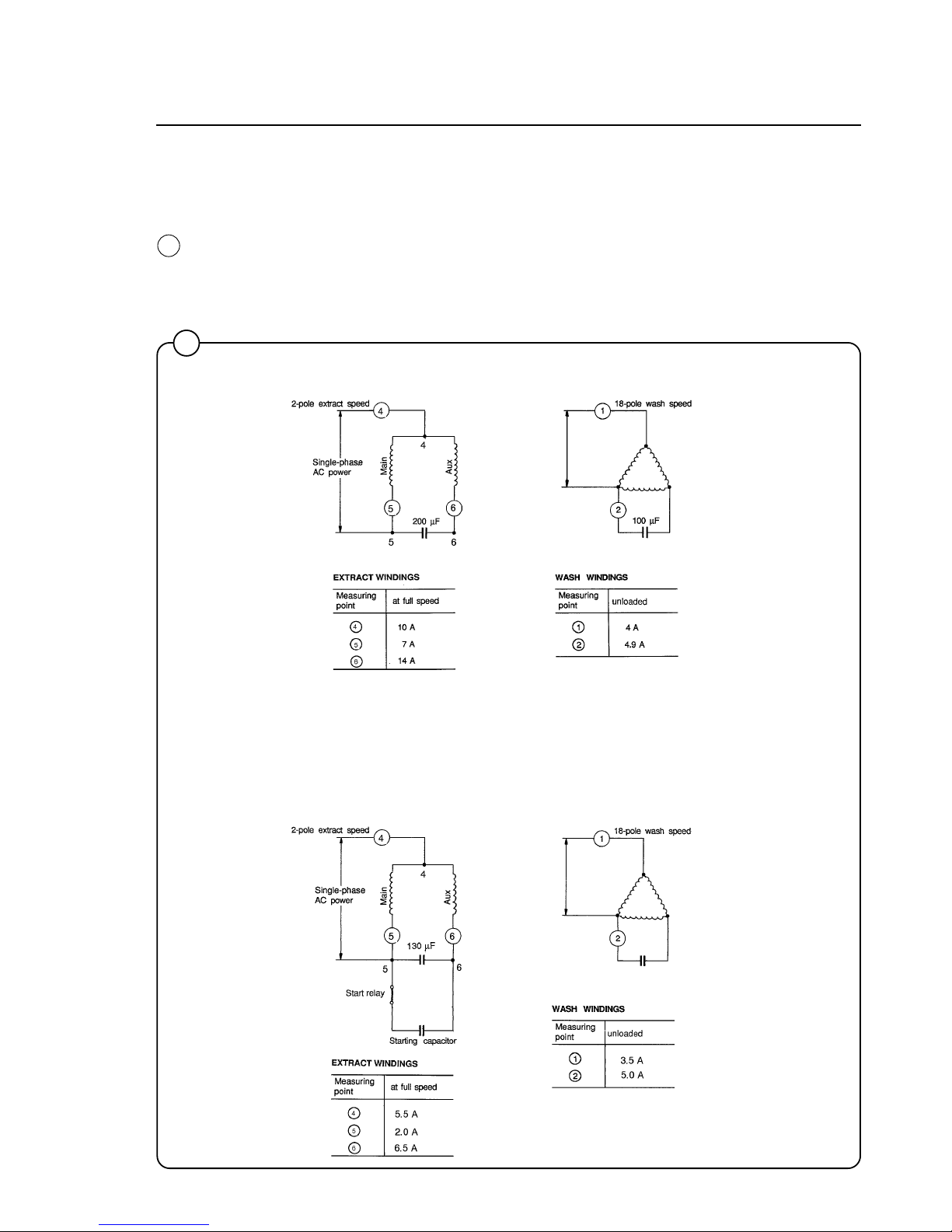
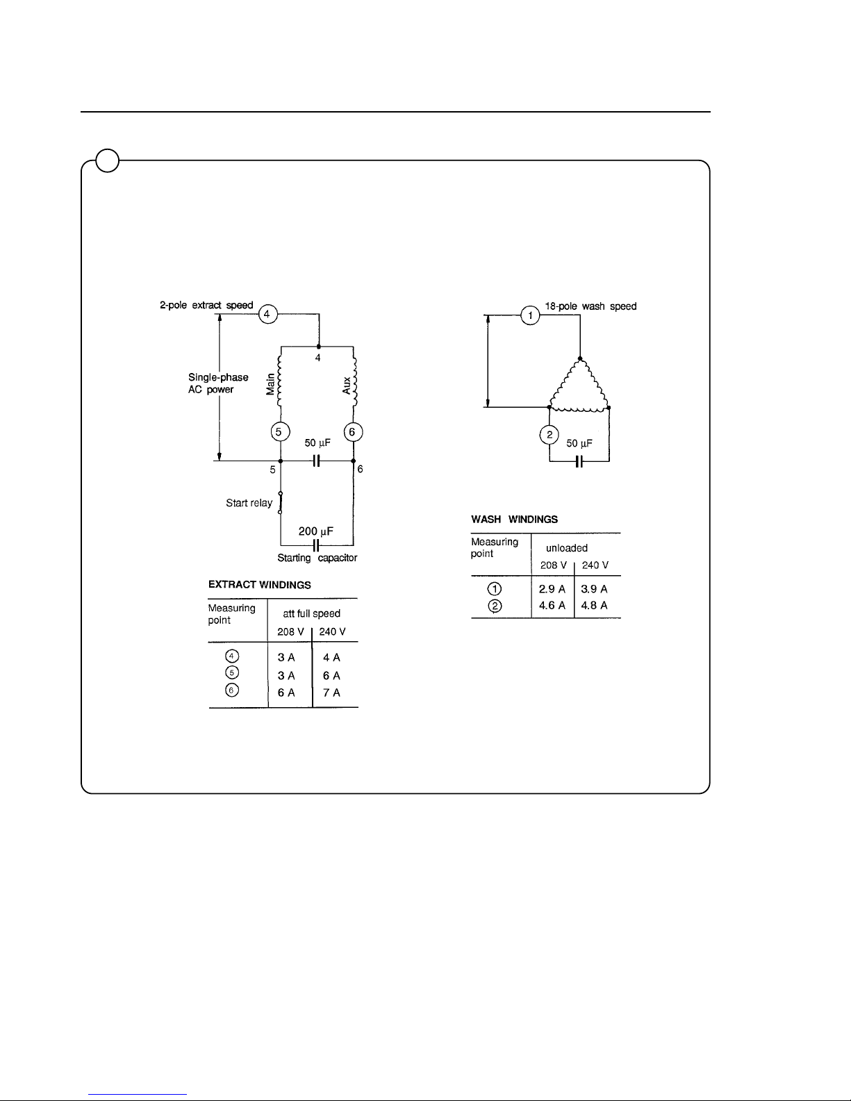
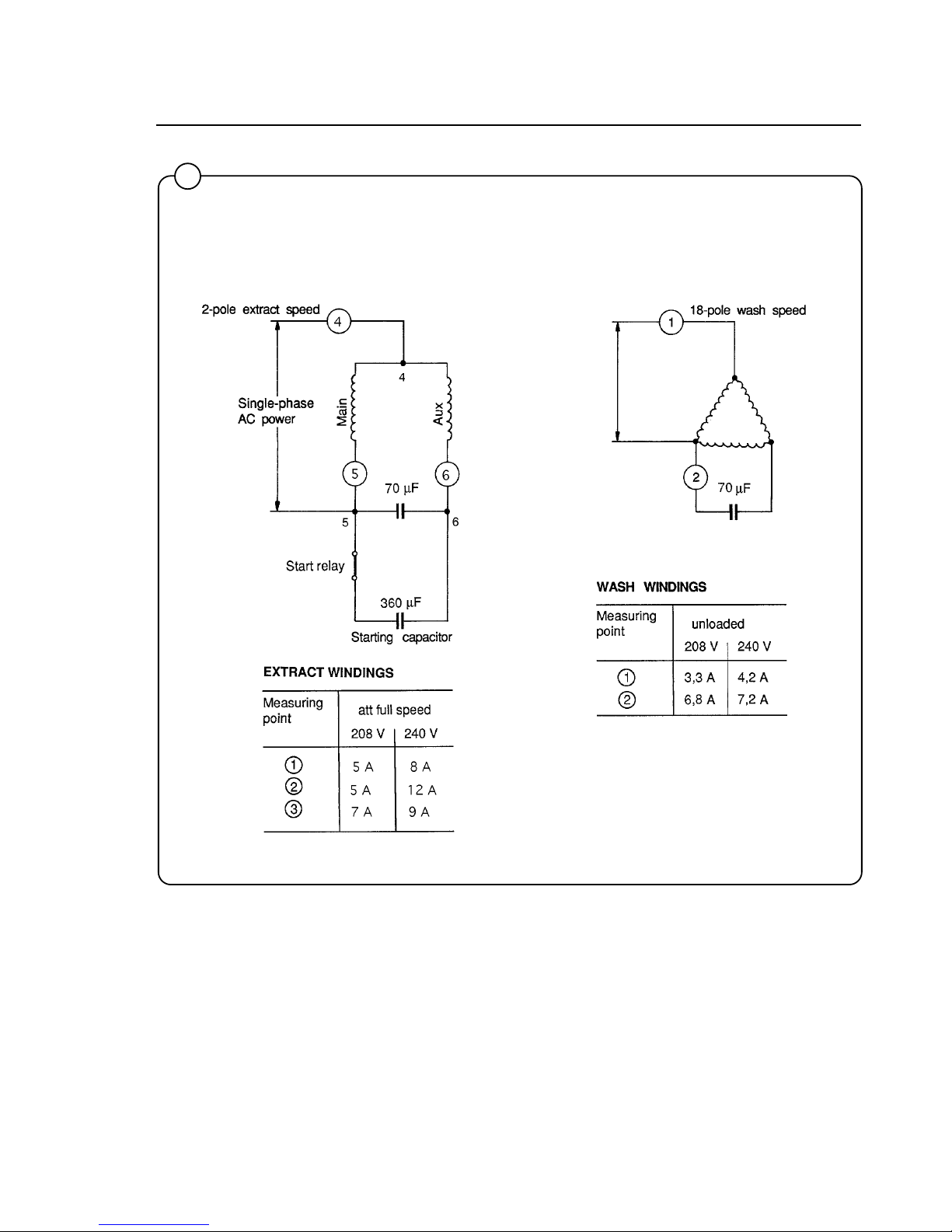
Principal wiring and points of measuring on single-phase
motors.
The numbers at the connection points refer to the terminal numbers at the motor connector plug.
The numbers in circles indicate points of ampere measurements.
Mechanical and electrical design
1216
68
W75 120 V 60 Hz single-phase
W105 120 V 60 Hz single-phase
Fig.
68
130 µF
200 µF
Page 50
46
68
Mechanical and electrical design
1700
W125 208-240 V 60 Hz single-phase
Page 51
47
68
Mechanical and electrical design
1791
W185 208-240 V 60 Hz single-phase
Page 52
48
Mechanical and electrical design
Motor connections
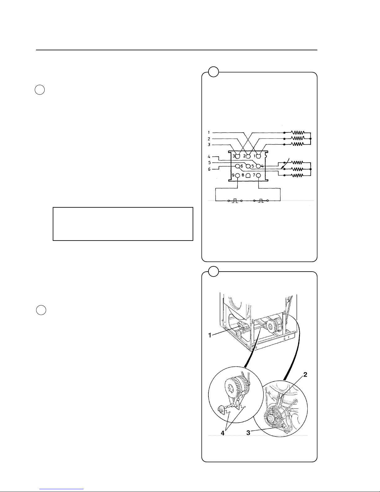
1, 2 and 3: wash speed (18-pole winding).
4, 5 and 6: extract speed (2-pole winding)
7 and 9: motor overload protector.
Motor overload protector
The motor is equipped with two self-resetting,
thermal overload protectors, situated one in each
of the windings of the stator. The protectors are
connected in series and will trip at a temperature
of 120°C (248°F) (3-phase) or 130°C (266°F)
(single phase). In the event the protectors fail
but the motor remains otherwise undamaged, an
overload protector may be mounted in the control
unit of the machine. Before making such installation check to ascertain that the windings are not
damaged. A burned out motor can be re-wound.
NOTE
Before connecting a separate overload
protector consult the local code.
Single-phase W125 and W185 machines are
also equipped with a manually set overload
protector mounted on the extract relay in the
control unit. This overload protector protects the
motor during the start-up of the extraction.
Removing the motor
• Remove the drain valve (1) from the long shaft
by pulling it straight up.
• Remove the tensioning unit (2) on the rear of
the motor.
• Disconnect the connector (3) placed
diagonally under the rear edge of the motor.
• Remove the two screws (4). Pull the shaft
forward slightly until the guide pins pull out of
the shaft brackets. Remove the motor unit.
70
69
0304
1157
Blue
White
Black
Black
White
LOW SPEED
HIGH SPEED
Overload protector
Blue
Fig.
69
Fig.
70
Page 53
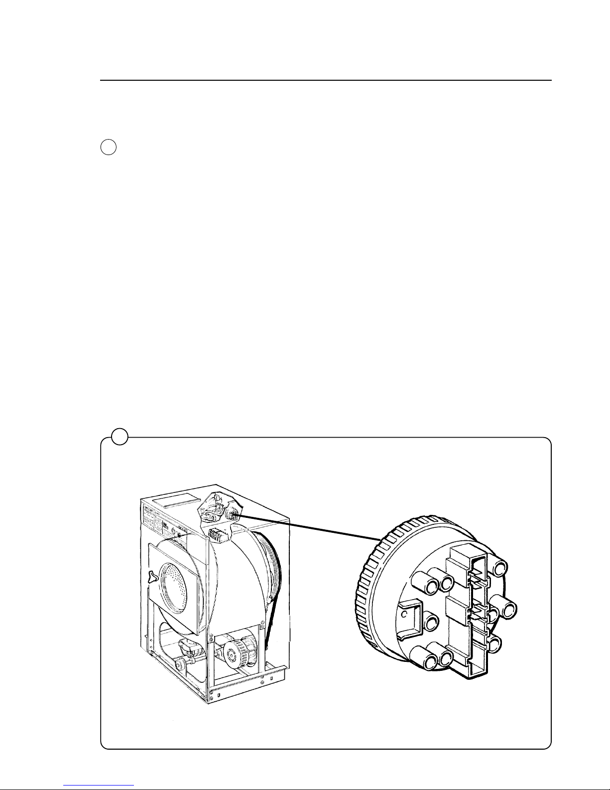
49
Mechanical and electrical design
71
1158
Water level controls
One pressure switch is used to control the correct water levels
during various cycles of the washing program.
Adjustment
All pressure switches are factory-calibrated to meet specific
requirements. The trip level for any one pressure switch can be
changed only within narrow limits because each trip range requires a different set of springs. Call Wascomat's Service Department at 516-371-0700 before attempting to adjust the level
control!
Water level
As a guide for checking the level control for proper functioning, the
normal level should be approximately at the bottom of the door
glass. It is primarily the reverse-wash mechanical action of the
washer which gets clothes clean, not the level of water or amount
of detergent. The water levels are set at the factory to get a full
load clean without wasting a drop of water, to save you money
and protect the environment.
Fig.
71
Page 54
50
Inlet valves
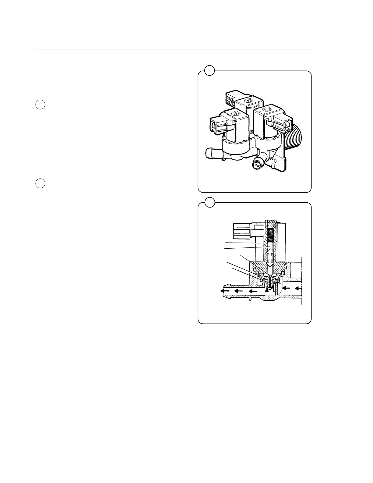
Construction
The valve has a single-inlet with either one, two
or three outlets, each with its own solenoid coil.
The body is made of heat-resistant polyamid
plastic and the solenoids encased in water-tight
plastic.
A filter screen on the inlet side prevents dirt from
entering the valve. Flow restrictors can be placed
at either the inlet or any of the outlets.
Operation
When the solenoid is energized, the springloaded plunger is drawn up and the pilot valve in
the center of the diaphragm open. Because of
the difference in diameter between the pilot valve
opening and the ventilating hole in the diaphragm, the pressure above the diaphragm drops
to a point where the admission pressure below
the diaphragm can lift the diaphragm, thus opening the valve.
When the current to the solenoid is cut off, the
plunger spring will press the plunger against the
pilot opening of the diaphragm. The pressure
above the diaphragm then rises to correspond to
the water inlet pressure and the pressure of the
spring will close the valve.
Mechanical and electrical design
72
1161
73
1185
solenoid
plunger
ventilating hole
diaphragm
pilot valve
Fig.
72
Fig.
73
Page 55
51
Mechanical and electrical design
76
1181
74
1186
75
1187
Maintenance instructions
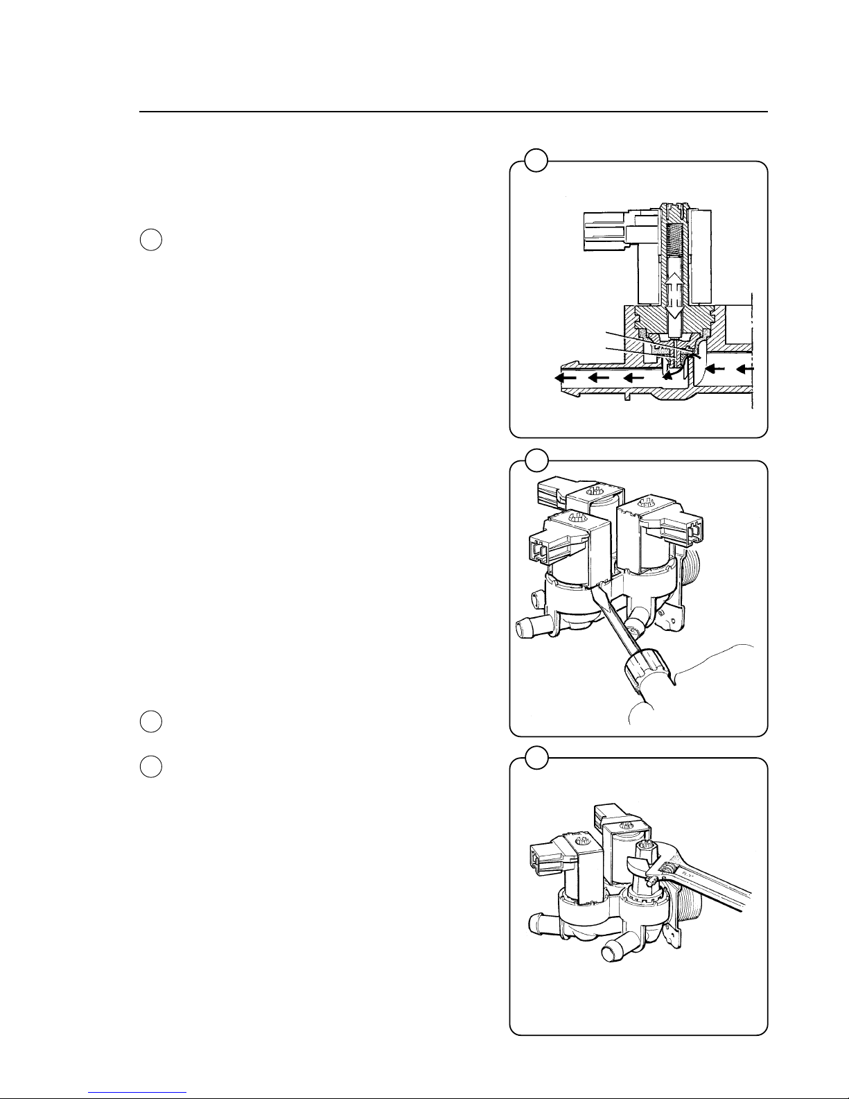
Lime scale can block the hole in the valve diaphragm and interfere with the function of the valve.
It is therefore advisable to disassemble and clean
the valve at certain regular intervals. The frequency depends on operating conditions and the
level of contamination in the water.
Trouble shooting
If the valve does not open
• Check that power is supplied to the coil.
• Check the coil with an instrument to determine
whether there is a break or a short circuit.
• Disassemble the valve (see below) and check
the openings in the valve diaphragm.
• Check the inlet strainer and clean as required.
• Undo the coil and clean the surfaces of the
magnetic core.
If the valve does not close
• Check that the coil is not live. The valve is
normally closed when the magnet is not
energised.
• Check the return spring.
• Check the diaphragm (pilot pressure opening).
Disassembling the valve
• Pull the coil straight upwards. Use a screwdriver if necessary to carefully undo the coil.
• Use the tool supplied with the machine
(attached to one of the hoses when the
machine is delivered) to open the valve
housing. Slide the tool over the protruding
plastic sleeve to that the pegs on the tool
engage the corresponding sockets in the
valve housing.
• Use a wrench or a pair of pliers and unscrew
the upper part of the valve housing.
Fig.
74
Fig.
75
Fig.
76
ventilating hole
pilot valve
Page 56
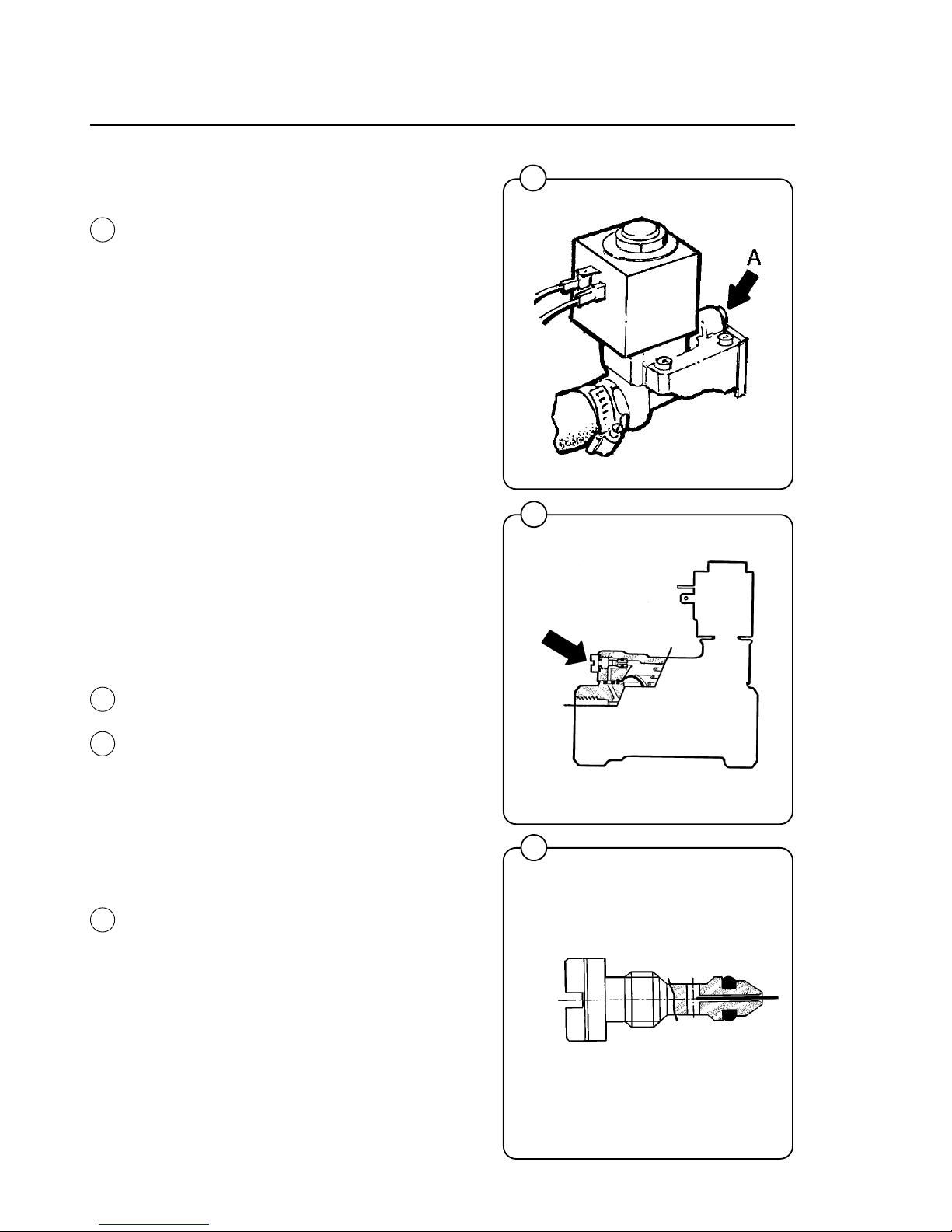
52
Mechanical and electrical design
79
0369
77
0311
78
0368
Inlet valve for W185
The water inlets have brass bodies with larger
cross section of the outlet in order to achieve a
shorter filling time for the machine.
Construction
The valve housing is made of pressed brass. The
spring-loaded plunger is made of stainless steel
and located at its lower end is a rubber gasket for
the pilot valve.
Operation
The valve is automatically operated by means of
a rubber diaphragm and a pilot valve in exactly
the same way as the supply injector valve.
NOTE: To strip, clean, re-assemble and
troubleshoot the inlet valve, follow the
instructions outlined for the supply injector
valve.
Clean out
At water temperatures of more than 60°C/140°F,
the lime deposits are heavily increased. This can
cause function problems due to blocking up the
equalizing orifice of the valve.
The fault can be eliminated by cleaning the
equalizing orifice (marked A).
If there are much deposits the orifice can be
changed from 0.5 mm to 0.8 mm. The screwhead
of the orifice is marked with 1 ring for the size of
0.5 mm and 2 rings for the size of 0.8 mm.
Clean the orifice as follows:
1. Shut off the main supply.
2. Unscrew the orifice.
3. Clean the hole in the orifice carefully with a
pin or similar not thicker than 0.5 resp. 0.8
mm.
4. Mount the orifice, be careful with sealing and
tighten.
5. Open the main supply.
Fig.
77
Fig.
77
Fig.
79
Fig.
78
Page 57
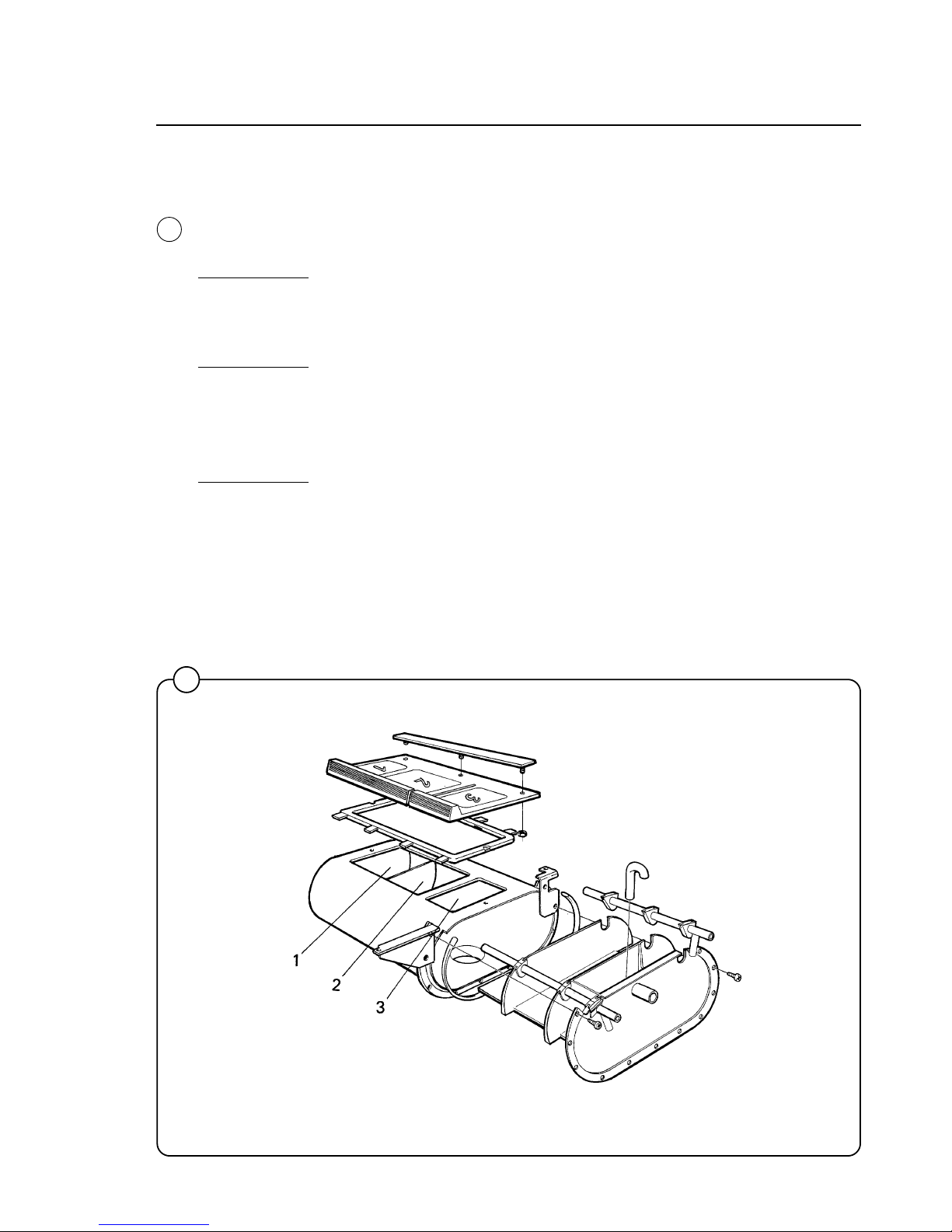
53
Mechanical and electrical design
80
1182
Soap supply box
The three-compartment soap supply box is located at the top of the machine.
Viewed from the front, the compartments marked with figures 1, 2 and 3 are
used as follows:
Compartment 1
This compartment is used for adding detergent at the beginning of the
Prewash cycle. Powders may be loaded immediately; for liquids, wait until
the display shows an arrow and the compartment flushes with water.
Compartment 2
This compartment is used for adding detergent at the beginning of the Wash
cycle. If bleach is used, it is added to this compartment when the display
arrow appears.
The insert is used to help prevent oversudsing.
Compartment 3
This compartment is used for liquid fabric softener, which is siphoned into
the drum at the start of the third rinse. Liquid softener may be added at the
beginning of the cycle or during the final rinse when the arrow appears.
Fig.
80
Page 58
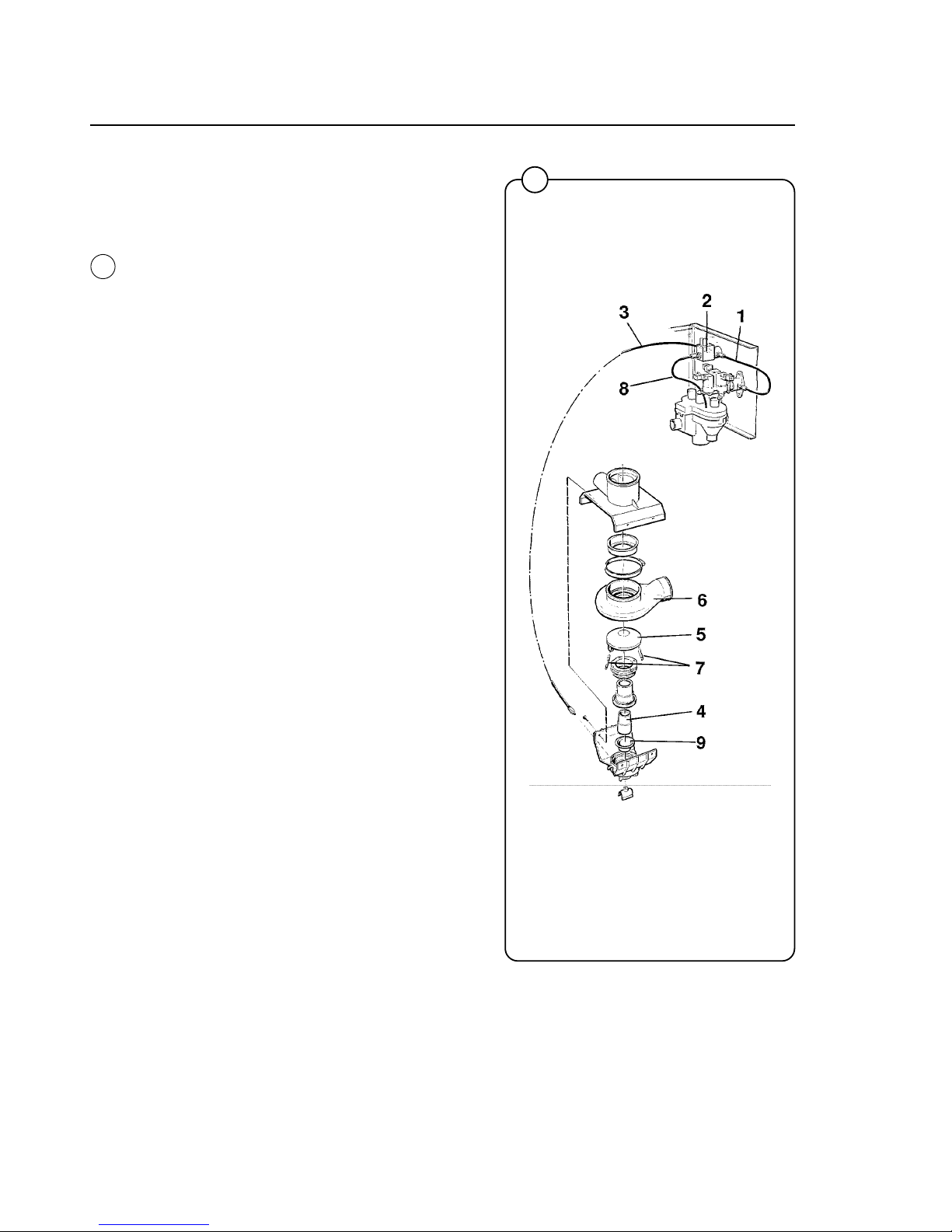
54
Mechanical and electrical design
81
1159
Drain valve
Description
The drain valve is operated by using the pressure
in the cold water intake. A tube (1) is connected
between the cold water intake and a solenoid
valve (2). When the solenoid valve is activated, it
opens and allows water to flow into the feeder
tube (3). The water presses up a piston (4),
which uses the pressure lid (5) to close the drain
valve rubber membrane. When the solenoid
valve cuts out, the water presure and the springs
(7) on the lid push the piston back, allowing the
water to pass the solenoid valve and drain out via
the return tube (8).
Trouble shooting
If the drain valve doesn’t close:
• Check that the solenoid valve (2) receives
electricity.
• Check that the solenoid valve and the tubes
are clear by:
- removing the drain hose (3).
- Check that water exits the hose when the
valve is activated.
• Check that the diaphragm (9) is undamaged.
If the drain valve doesn’t open:
• Check that the return tube (8) is open.
• Check that the piston (4) doesn’t seize.
Fig.
81
Page 59
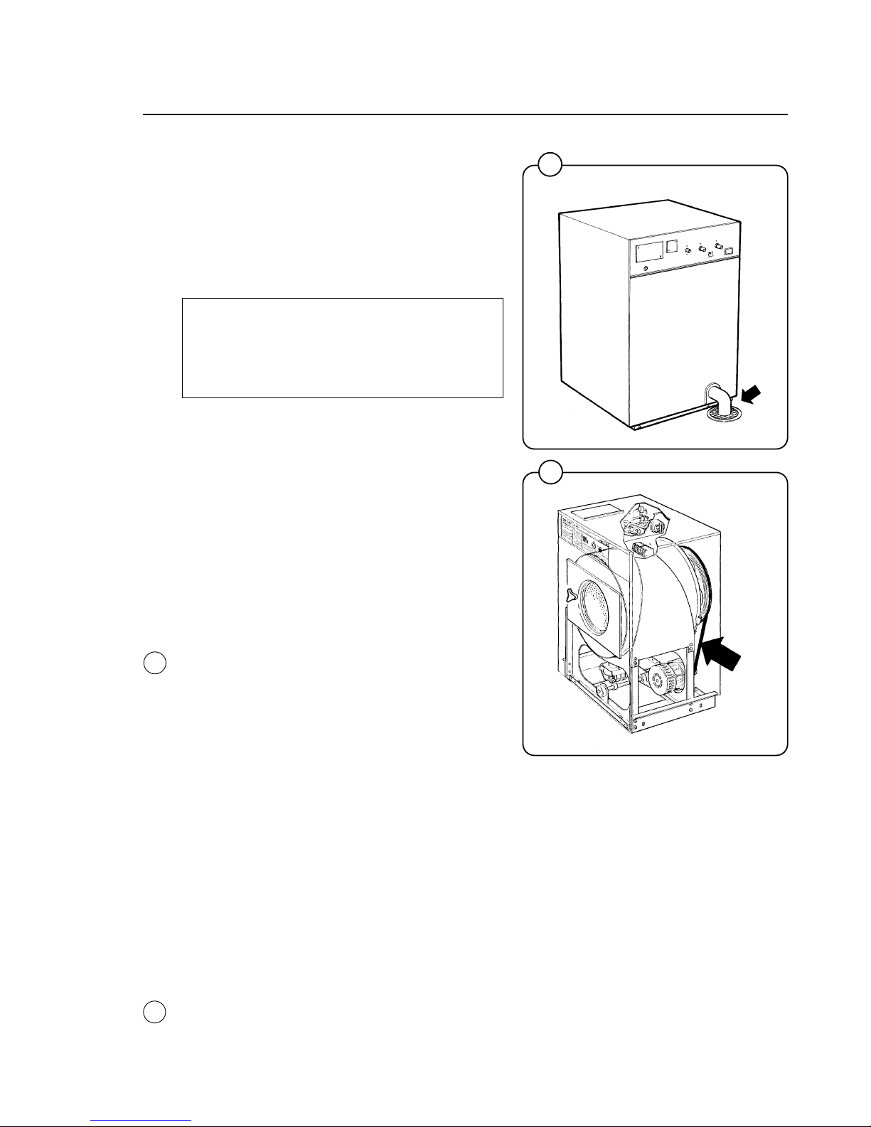
55
Maintenance
Preventive maintenance has been reduced to a
minimum by the careful design of reliable components and material.
However, the following measures should be
taken at regular intervals and in proportion to the
hours of service.
IMPORTANT!
Make certain that all electrical power to
the machine is shut off before removing
top or rear panels.
Daily
• Check the door lock and interlock before
starting operations.
• The soap supply box should be cleaned at the
end of each working day as follows:
- Use a spatula to scrape loose any deter-
gent which may have stuck on the inside of
the dispenser.
- Flush the loosened detergent with warm
water.
- Wipe dry and leave lid open.
• Check that the drain valve does not leak and
that it opens properly.
• Check that the door does not leak. Clean
residual detergent and foreign matter from the
door gasket.
• Wipe the outside of the machine.
• When the machine is not in use, leave door
slightly open to allow moisture to evaporate.
Weekly
• Remove the top panel and carefully clean
the rubber gasket on top of the soap box so it
tightly seals to the top panel. If you do not
maintain a tight seal you risk suds overflow onto
the door lock.
Every three months
• Remove the hose from the drain connection
and clean the inside of the drain valve.
• Remove the rear panel of the machine and
check that the V-belt of the wash motor is
undamaged and correctly tensioned.
Maintenance
82
1833
83
1207
Fig.
82
Fig.
83
Page 60
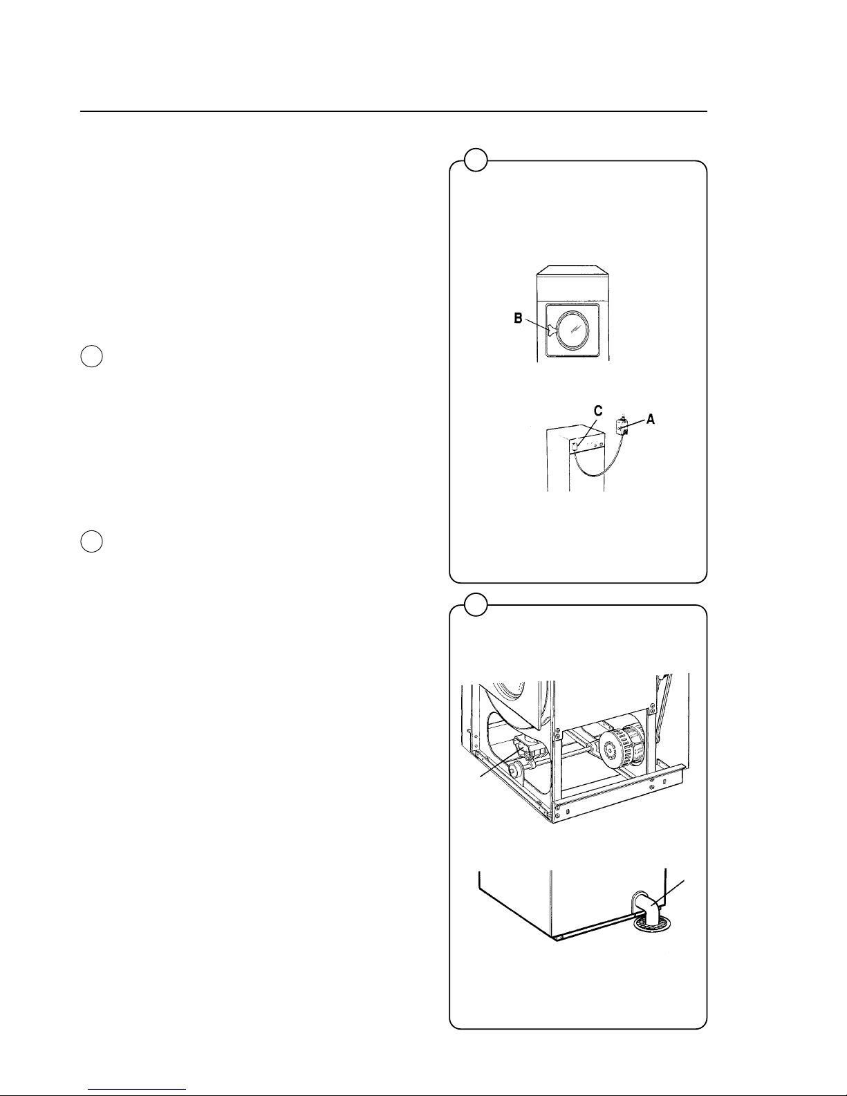
56
• Check that all tubing, piping and connections
are free from leaks.
• Wipe and clean the inside of the machine,
making sure that the control components are
protected from moisture and dirt during the
cleaning operation.
Trouble shooting
If the machine does not start
A Check the circuit breaker in the power line to
the machine.
B Check the door lock, including cable.
C Check the glass cartridge fuses.
D Check for loose wires at main power terminal
block.
If water does not drain
A Check the drain valve for clog. Check the
drain solenoid (located next to the water
valves) for proper operation.
B Disconnect the drain hose connected to the
main drain line. If a full flow of water comes
out, the problem is in the main drain line. If
water flow is slow, the problem is a clog
between the drain valve and the drum. Clean
out the drain valve completely, including the
rubber boot at the top of the drain valve.
If fuses continually blow
A Check the door lock, including cable
B Check for short circuit.
If timer rapid advances or stops during cycle
A Check the door lock, including cable.
Trouble shooting
1208
85
1209
A
B
B
C
A
84
Fig.
84
Fig.
85
Page 61
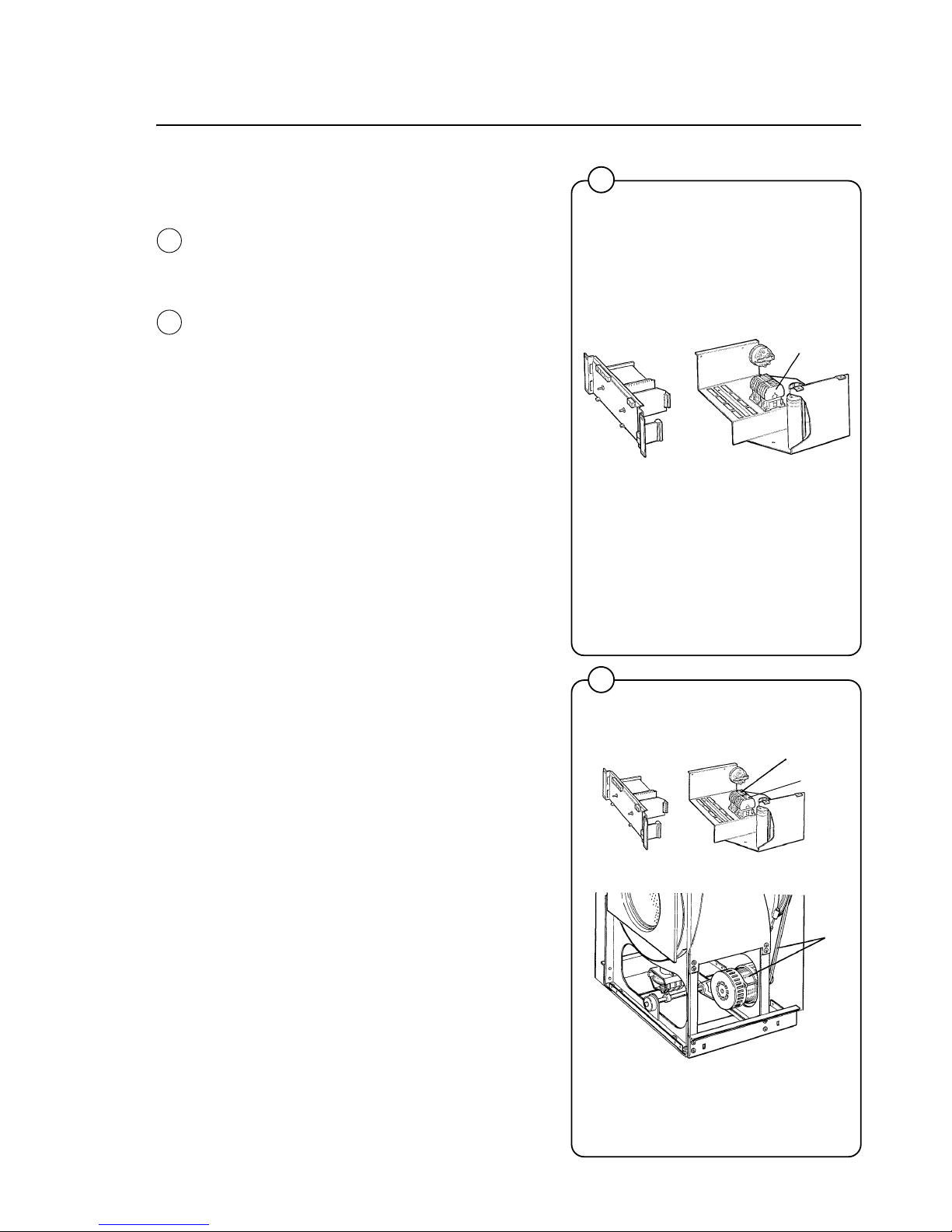
57
Trouble shooting
86
1210
87
1211
A
A
B
C
If machine does not extract
A Check the extract relay and relay coil for
proper operation.
B Check the door lock, including cable.
If motor does not operate at wash speed
A Check the wash relay.
B Check the normally-closed contact of extract
relay.
C Check the motor and V-belt.
D Review procedures outlined under section "If
machine does not start" above.
Fig.
86
Fig.
87
Page 62
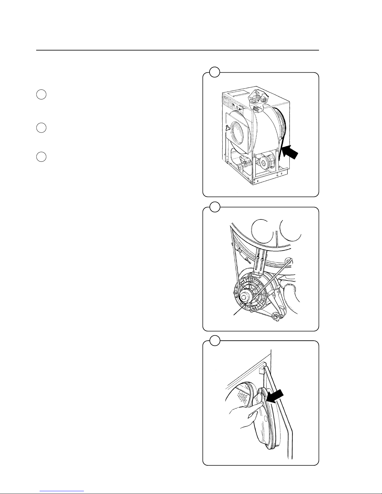
58
If the machine runs slowly on wash speed or
there is a slapping or thumping noise.
A Replace V-belts
If a metallic noise can be heard at the rear of
machine
A Tighten pulley on motor shaft
If the door is leaking
A Check the door gasket. If the gasket is in good
condition, rotate the gasket 180 degrees by
hand to even out the compression pattern, or
wrap a nylon cord around the entire gasket,
using the slit provided, so the gasket applies
pressure to the outer cylinder.
Trouble shooting
88
1207
1175
1176
89
90
A
Fig.
88
Fig.
89
Fig.
90
Page 63
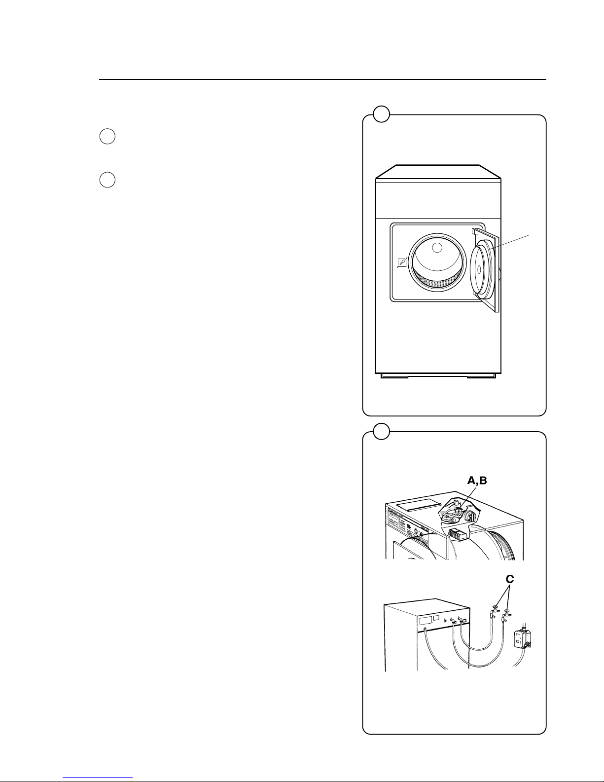
59
If there is a leaking around the glass
A Replace door gasket if worn.
If water does not enter the machine.
A Check the valve coils on inlet valves.
B Check wires leading to valve coils.
C Be sure water shut-off valves are in open
position!
Trouble shooting
91
1212
92
Fig.
92
1837
Fig.
91
A
Page 64
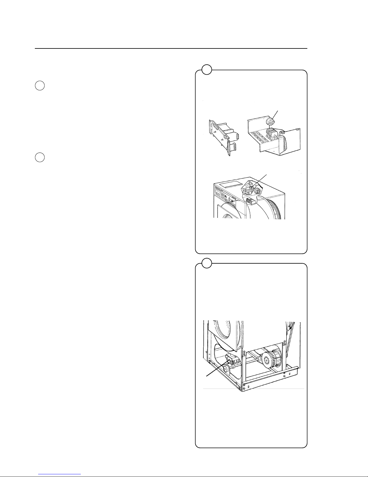
60
If water continues to fill without stopping.
A Check the hose attached to level control unit.
B Check the inlet valves for dirt underneath the
valve diaphragm. To localize, shut off power.
If water continues to flow, inlet valves have
foreign material in them and should be thoroughly cleaned.
If water continues to flow without filling the
machine.
A Check seating of the drain valve.
Trouble shooting
93
1214
94
1215
A
B
A
Fig.
93
Fig.
94
Page 65
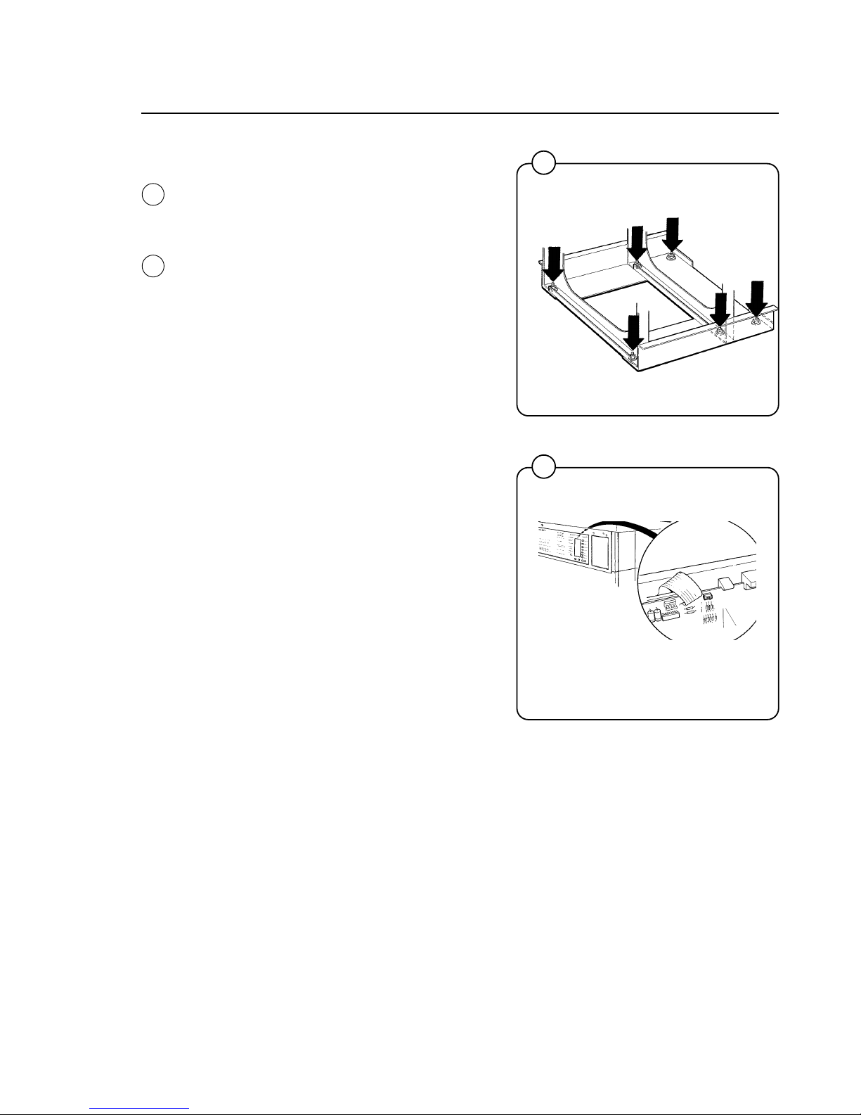
61
If the machine or panels vibrate
Tighten the bolts and level the washer.
If keypad buttons do not work
A Check the ribbon connector for proper contact
on the microprocessor board.
B Replace the keypad.
Trouble shooting
95
1140
96
1476
Fig.
95
Fig.
96
 Loading...