

Wascom EMERALD W75ES, EMERALD W185ES, EMERALD W105ES, EMERALD W125ES Operating & Maintenance Manual
WARNING: ALL OPERATING AND MAINTENANCE PROCEDURES SHOWN ON THE NEXT
PAGE OF THIS MANUAL MUST BE FOLLOWED DAILY FOR PROPER OPERATION OF
YOUR WASCOMAT MACHINE.
PLEASE ENTER THE FOLLOWING INFORMATION AS IT APPEARS ON THE WASHER
DATA PLATE LOCATED AT TOP LEFT OF THE REAR PANEL. SERIAL NUMBER IS ALSO
LOCATED ON A STICKER ON THE INSIDE OF THE DOOR.
MAKE CERTAIN TO KEEP THIS MANUAL IN A SECURE PLACE FOR FUTURE
REFERENCE.
MACHINE TYPE OR MODEL
MACHINE SERIAL NUMBER(S)
ELECTRICAL CHARACTERISTICS:________ VOLTS, _______ PHASE, ______ HZ.
OPERATING & MAINTENANCE MANUAL
WASCOMAT
W75ES – W105ES – W125ES – W185ES
EMERALD SERIES
471 1562-66/01
95.32

NOTICE TO: OWNERS, OPERATORS AND DEALERS OF WASCOMAT MACHINES
IMPROPER INSTALLATION AND INADEQUATE MAINTENANCE, POOR HOUSEKEEPING AND WILLFUL
NEGLECT OR BYPASSING OF SAFETY DEVICES MAY RESULT IN SERIOUS ACCIDENTS OR INJURY.
TO ASSURE THE SAFETY OF CUSTOMERS AND/OR OPERATORS OF YOUR MACHINE, THE FOLLOWING MAINTENANCE CHECKS MUST BE PERFORMED ON A DAILY BASIS.
1. Prior to operation of the machine, check to make certain that all operating instructions and
warning signs are affixed to the machine and legible. (See the following page of this manual
for description and location of the signs.) Missing or illegible ones must be replaced immediately. Be sure you have spare signs and labels available at all times. These can be
obtained from your dealer or Wascomat.
2. Check the door safety interlock, as follows:
(a) OPEN THE DOOR of the machine and attempt to start in the normal manner:
For coin-operated models, select a program, insert the proper coins and press the
START button.
For manually operated models, select a cycle and press the START button.
THE MACHINE(S) SHOULD NOT START !
(b) CLOSE THE DOOR and press the START button. Now attempt to
open the door by turning the door handle. The door should remain locked!
If the machine can start with the door open, or can continue to operate with the
door unlocked, the door lock is no longer operating properly. The machine
must be placed out of order and the lock immediately replaced.
(See the door lock section of the manual.)
3. DO NOT UNDER ANY CIRCUMSTANCES ATTEMPT TO BYPASS OR REWIRE ANY OF
THE MACHINE SAFETY DEVICES AS THIS CAN RESULT IN SERIOUS ACCIDENTS.
4. Be sure to keep the machine(s) in proper working order: Follow all maintenance and
safety procedures. Further information regarding machine safety, service and parts can be
obtained from your dealer or from Wascomat through its Teletech Service Hotline - (516)
371-0700.
All requests for assistance must include the model, serial number and electrical characteristics as
they appear on the machine identification plate at the top rear of the washer. Insert this information
in the space provided on the previous page of this manual. You can also find the serial number on
a sticker on the inside of the door.
5. WARNING: DO NOT OPERATE MACHINE(S) WITH SAFETY DEVICES BYPASSED, REWIRED OR
INOPERATIVE! DO NOT OPEN MACHINE DOOR UNTIL DRUM HAS STOPPED ROTATING!

DO NOT ATTEMPT TO OPEN DOOR
UNTIL PROGRAM HAS FINISHED AND
DRUM HAS STOPPED ROTATING.
WARNING !
If you need to order more safety or warning
signs, call Wascomat's parts department at
516-371-2000, or call your local dealer.
471 7651-17
471 76 62 02
SAFETY AND WARNINGS SIGNS
Replace If Missing Or Illegible
One or more of these signs must be affixed on each machine as indicated, when not included as part of the front instruction panel.
LOCATED ON THE OPERATING INSTRUCTION SIGN OF THE MACHINE:
LOCATED AT THE REAR OF THE MACHINE:
INSTALLATION AND MAINTENANCE WARNINGS
1. This machine MUST be securely bolted to an uncovered concrete floor, according to
the installation instructions, to reduce the risk of fire and to prevent serious injury, or
damage to the machine.
2. If installed on a floor of combustible material, the floor area below this machine must
be covered by a metal sheet extending to the outer edges of the machine.
3. This machine MUST be connected to a dedicated electrical circuit to which no other
lighting unit or general purpose receptacle is connected. Use copper conductor only.
4. This machine MUST be serviced and operated in compliance with manufacturer's
instructions. CHECK DOOR LOCKS EVERY DAY FOR PROPER OPERATION TO PRE
VENT INJURY OR DAMAGE. IF THE DOOR LOCK FAILS TO OPERATE PROPERLY,
PLACE THE MACHINE OUT OF ORDER UNTIL THE PROBLEM IS CORRECTED.
5. Disconnect power prior to servicing of machine.
6. To remove the top panel for service on those models on which it is secured by screws
at the rear, first remove the screws. Be certain to reinstall them when remounting the
top panel. To remove the top panel for service on those models on which it is secured
by one or two keylocks, use the keys originally shipped in the drum package. Be
certain to relock after remounting the top panel.
MANUFACTURED BY WASCATOR
DISTRIBUTED BY WASCOMAT INWOOD, NEW YORK, USA
LOCATED ON THE DOOR:

Contents
Wascomat W75ES • W105ES • W125ES • W185ES
EMERALD SERIES
Introduction ......................................................................1
Technical data.................................................................. 2
Installation ........................................................................7
Operating Instructions.................................................... 15
Fault-finding & Servicing Programs ............................... 21
Programming..................................................................25
Wash Cyclels .................................................................29
Mechanical and Electrical Design .................................. 38
Maintenance...................................................................55
Troubleshooting .............................................................56
The manufacturer reservs the right to make changes to design and
material specifications.
Safety instructions
• The machine is designed for water washing only.
• The machine must not be used by children.
• All installation operations are to be carried out by qualified
personnel. Licensed personnel are necessary for all electric
power wiring.
• The interlock of the door must be checked daily for proper
operation and must not be bypased.
• Any water leaks must be repaired immediately.
• All service personnel must be fully familiar with the operating
manual before attempting any repair or maintenance of the
machine.
• The machine must not be sprayed with water, otherwise short
circuiting may occur.
• Volatile or flammable liquids are not to be used.
1
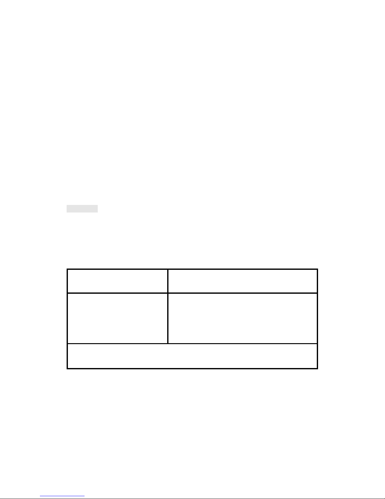
Introduction
General
Wascomat EMERALD SERIES washer/extractors have been developed to
meet the needs of state-of-the-art professional laundromats. EMERALD
models are unique because you can program different prices for the seven
wash cycles, giving the customer a real choice and allowing you to maximize revenue by charging what each cycle is worth. In addition, you can
charge a higher price if the customer selects the Extra Extract option. Using
an external clock and wiring harness, these models may be programmed to
lower prices by any percentage between any hours of any days, for the
ultimate in pricing flexibility!
The seven cycles offer different water temperatures, wash times, extraction
times, and normal or gentle drum rotation. EMERALD SERIES washers
achieve maximum environmental efficiency because only the minimum
amount of water is used for each cycle, which vary in duration.
When ordering spare parts or contacting Wascomat or your dealer for
service, always give the machine serial number, model, voltage and other
electrical characteristics appearing on the data plate at the top left of the
rear panel of the machine. The serial number is also printed on a sticker
inside the door.
KEEP THIS MANUAL IN A SAFE PLACE FOR FUTURE REFERENCE!
G135
1
Fig.
1

Technical data
2
Technical data Wascomat W75ES EMERALD SERIES
Dry load capacity up to 18 lbs
Overall dimensions Width 660 mm 26 in
Depth 678 mm 26 11/16 in
Height 1050 mm 41 11/32 in
Net weight 107 kg 235 lbs
Dyn force 1.2±2.6 kN 290±620 lbs. force
Crated dimensions Volume 0.62 m
3
21.9 cu.ft
Weight 117 kg 257 lbs
Inner drum Diameter 520 mm 20 1/2 in
Depth 356 mm 14 in
Volume 75 litre 2.7 cu.ft
Speed of rotation Wash 54 r.p.m.
Extraction 543 r.p.m.
G-factor During wash 0.8
During extraction 90
Motor speed During wash 344 r.p.m.
During extraction 3514 r.p.m.
Voltage requirements Choice:
120 V 1-phase 60 Hz
or
208-240 V 3-Phase 60 Hz
Rated output power Motor, wash, 3-phase 110 W
0.15 HP
Motor, extract., 3-phase 550 W
0.75 HP
Motor, wash, 1-phase 110 W
0.15 HP
Motor, extract., 1-phase 370 W
0.5 HP
Overcurrent protection Three-phase 15 A
Single-phase 20 A
Water connections
Recommended water pressure 2-6 kp/cm
2
25-85 psi
Hose connection, water 20 DN 3/4 in
Hose connection, drain 74 mm 3 in

Technical data
3
Technical data W105ES EMERALD SERIES
Dry load capacity up to 25 lbs
Overall dimensions Width 660 mm 26 in
Depth 795 mm 31 5/16 in
Height 1050 mm 41 11/32 in
Net weight 147 kg 323 lbs
Dyn force 1.7 ±3.4 kN 408±816 lbs. force
Crated dimensions Volume 0.65 m
3
23.0 cu.ft.
Weight 158 kg 348 lbs
Inner drum Diameter 520 mm 20 1/2 in
Depth 473 mm 18 5/8 in
Volume 100 litre 3.6 cu.ft
Speed of rotation Wash 54 r.p.m.
Extraction 543 r.p.m.
G-factor During wash 0.8
During extraction 90
Motor speed During wash 344 r.p.m.
During extraction 3514 r.p.m.
Voltage requirements Choice:
120 V 1-phase 60 Hz
or
208-240 V 3-Phase 60 Hz
Rated output power Motor, wash 3-phase 150 W
0.2 HP
Motor, extract. 3-phase 900 W
1.2 HP
Motor, wash 1-phase 140 W
0.18 HP
Motor, extract. 1-phase 550 W
0.75 HP
Overcurrent protection Three-phase 15 A
Single-phase 20 A
Water connections
Recommended water pressure 2-6 kp/cm
2
25-85 psi
Hose connection, water 20 DN 3/4" in
Hose connection, drain 74 mm 3" in

4
Technical data
Technical data Wascomat W125 ES EMERALD SERIES
Dry load capacity up to 35 lbs
Overall dimensions Width
Depth 995 mm 39 3/16 in
Height 1196 mm 47 3/32 in
Net weight 210 kg 462 lbs
Dyn force 2.4±4.8 kN 576±1152 lbs. force
Crated dimensions Volume 1.06 m
3
39 cu.ft.
Weight 222 kg 489 lbs
Inner drum Diameter 620 mm 24 1/2 in
Depth 520 mm 20 1/2 in
Volume 157 litre 5.65 cu.ft
Speed of rotation Wash 52 r.p.m.
Extraction 500 r.p.m.
G-factor During wash 0.9
During extraction 87
Motor speed During wash 330 r.p.m
During extraction 3450 r.p.m
Voltage requirements Choice:
208-240 V 1-phase 60 Hz
or
208-240 V 3-Phase 60 Hz
Rated output power Motor, wash 3-phase 300 W
0.4 HP
Motor, extract. 3-phase 1300 W
1.8 HP
Motor, wash 1-phase 280 W
0.4 HP
Motor, extract. 1-phase 1300 W
1,8 HP
Overcurrent protection Three-phase 15 A
Single-phase 20 A
Water connections
Recommended water pressure 2-6 kp/cm
2
25-85 psi
Hose connection, water 20 DN 3/4" in
Hose connection, drain 74 mm 3" in

Technical data
Technical data Wascomat W185 ES EMERALD SERIES
Dry load capacity up to 50 lbs
Overall dimensions Width 860 mm 33 7/8 in
Depth 1085 mm 42 3/4 in
Height 1315 mm 51 3/4 in
Net weight 264 kg 582 lbs
Dyn force 3.1±5.2 kN 744±1248 lbs. force
Crated dimensions Volume 1.42 m
3
50.2 cu.ft.
Weight 275 kg 606 lbs
Inner drum Diameter 700 mm 27 9/16 in
Depth 600 mm 23 5/8 in
Volume 230 litre 8.1 cu.ft
Speed of rotation Wash 45 r.p.m.
Extraction 455 r.p.m.
G-factor During wash 0.8
During extraction 81
Motor speed During wash 360 r.p.m
During extraction 3480 r.p.m
Voltage requirements Choice:
208-240 V 1-phase 60 Hz
or
208-240 V 3-Phase 60 Hz
Rated output power Motor, wash 3-phase 400 W
0.55 HP
Motor, extract. 3-phase 2000 W
2.7 HP
Motor, wash 1-phase 400 W
0.55 HP
Motor, extract. 1-phase 1800 W
2.4 HP
Overcurrent protection Three-phase 15 A
Single-phase 20 A
Water connections
Recommended water pressure 2-6 kp/cm
2
25-85 psi
Hose connection, water 20 DN 3/4" in
Hose connection, drain 74 mm 3" in
5

Outline and dimensions
Technical data
6
1 Cold water
2 Hot water
3 Hot water (W185)
4 Drain outlet
5 Electrical + price reduction connections
6 Door
7 Slip-lock door handle
8 Emerald control panel
9 Coin-meter
10 Supplies compartments
W75 W105 W125 W185
mm inches mm inches mm inches mm inches
A 1050 41 5/16 1050 41 5/16 1196 47 1/16 1315 51 3/4
B 437 17 3/16 437 17 3/16 465 18 5/16 540 21 1/4
C 660 26 660 26 775 30 1/2 860 33 7/8
D 678 26 11/16 795 31 5/16 995 39 3/16 1085 42 11/16
E 895 35 1/4 895 35 1/4 1040 40 15/16 1160 45 11/16
F 100 3 15/16 100 3 15/16 100 3 15/16 100 3 15/16
G 125 4 15/16 125 4 15/16 270 10 5/8 260 10 1/4
H 980 38 9/16 980 38 9/16 1135 44 11/16 1255 49 7/16
J – – – – – – 1215 47 13/16
K 890 35 890 35 1035 40 3/4 1155 45 1/2
L – – – – – – 295 11 5/8
M 205 8 1/6 205 8 1/16 205 8 1/16 205 8 1/16
N 160 6 5/16 160 6 5/16 160 6 5/16 160 6 5/16
3210
D
C
10
8
7
6
9
B
A
E
4
G
F
KJH
5
2
3
1
M
N
L
W75 W105 W125 W185
mm inches mm inches mm inches mm inches
A 364 14 11/32 481 18 15/16 508 20 600 23 2/3
B 593 23 11/32 710 27 15/16 910 35 13/16 960 37 3/4
C 648 25 1/2 760 29 15/16 1031 40 9/16 1078 42 7/16
D 100 4 100 4 142 5 9/16 142 5 9/16
E 530 20 7/8 530 20 7/8 600 23 5/8 700 27 9/16
G 700 27 9/16 700 27 9/16 800 31 1/2 880 34 2/3
H 643 25 5/16 715,6 28 3/16 786 30 15/16 922 36 1/8
I - - - - 991 39 1090 42 7/8
K - - - - 281 11 236 9 7/16
Installation
2
3
4
0271
1677
1132
Installation
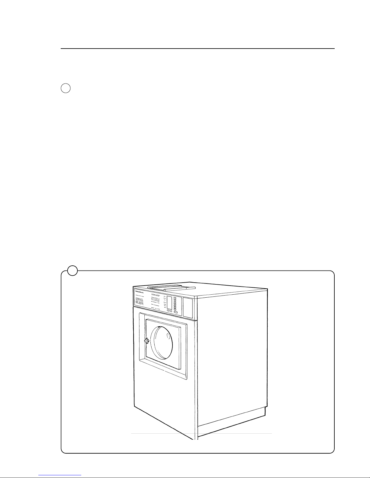
Machine foundation
The machines are designed to be securely bolted
to a concrete pad. A template showing the size of
the pad and positioning of the bolts is delivered
with each machine.
For installation on an existing concrete floor, the
floor must be at least 8" thick and of good quality.
If the floor does not meet these requirements,
then a 6-8" high concrete pad should be made. A
prefabricated steel base is available for mounting
machines without pouring a pad.
Follow the instructions below when making a
concrete foundation:
1. Decide where to place the machine and
consider maintenance requirements, i.e.
determine a suitable distance from the rear of
the pad to the wall, and the distance from the
pad to the nearest side wall. The distance
should be at least 16 and 12 inches,
respectively. Leave 3/4'' between washers.
2. Break up the floor to a minimum depth of 3
inches, making sure that the sides of the hole
slope away - the bottom of the hole should be
5 inches longer than the upper length.
3. Wet the hole well. Brush the bottom and sides
with cement grout.
4. Prepare a casing and fill with 3.000 PSI
concrete to form pad. Make sure the
foundation is level.
5.
Use the template to position the bolts
correctly. Bolts are to extend 1 1/2" above the
concrete.
NOTE: A prefabricated steel frame, designed
to be placed in the concrete instead of the
individual mounting bolts, is available.
7
Fig.
2
Fig.
3
Fig.
4
B = machine outline to edge of front panel
C, G = minimum foundation for one machine
Installation
5
6
7
0274
0950
1133
NOTE: Install the W105ES using the front and
rear pairs of bolt holes. The middle pair is
used when a W105ES is being installed in
replacement of a W73, W74 or W75 washer.
In that case the rear bolt holes are not
necessary but may also be used.
NOTE: If you form a lip on top of the concrete
pad in front of the washers, be sure you leave
enough room to remove the bolts which
secure the bottom of the front panel and
enough room to swing out and remove the
panel!
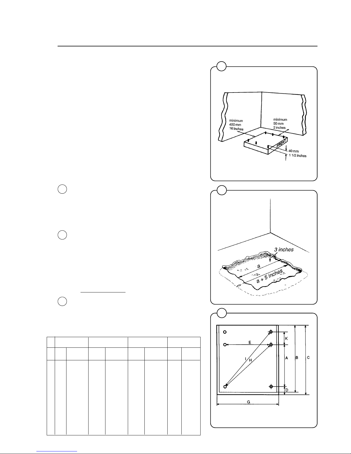
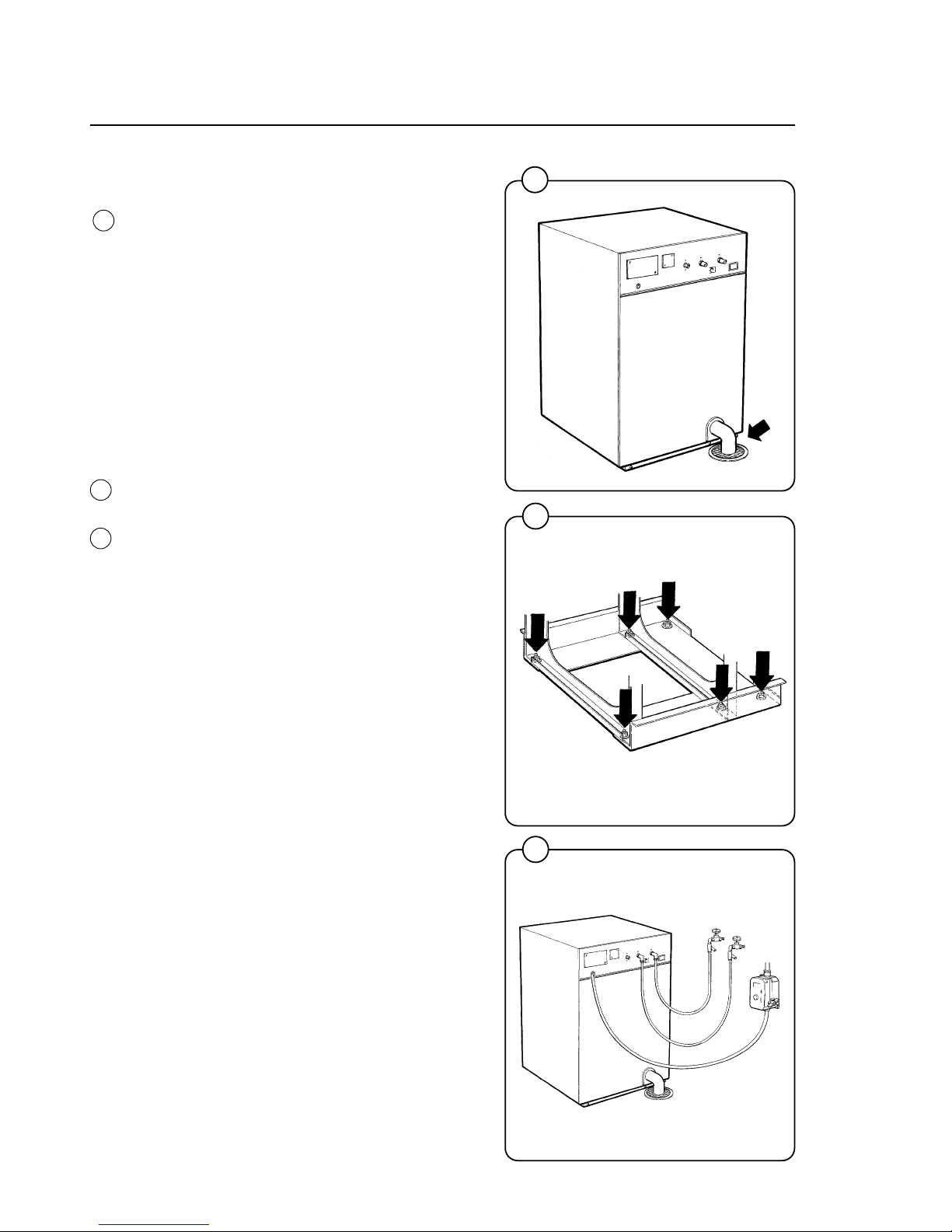
Mechanical installation
• Place wide steel shims on the concrete foundation over the bolts.
• Lift the machine and lower it in position. Never
use the door or the door handle to lift or lower
the machine.
• Check that the machine is level front-to-rear
and side-to-side and standing firmly on the
four (W75, W105) or six (W125 W185) supporting points. Spacing washers must be
mounted if one or more of these points is not
resting against the concrete.
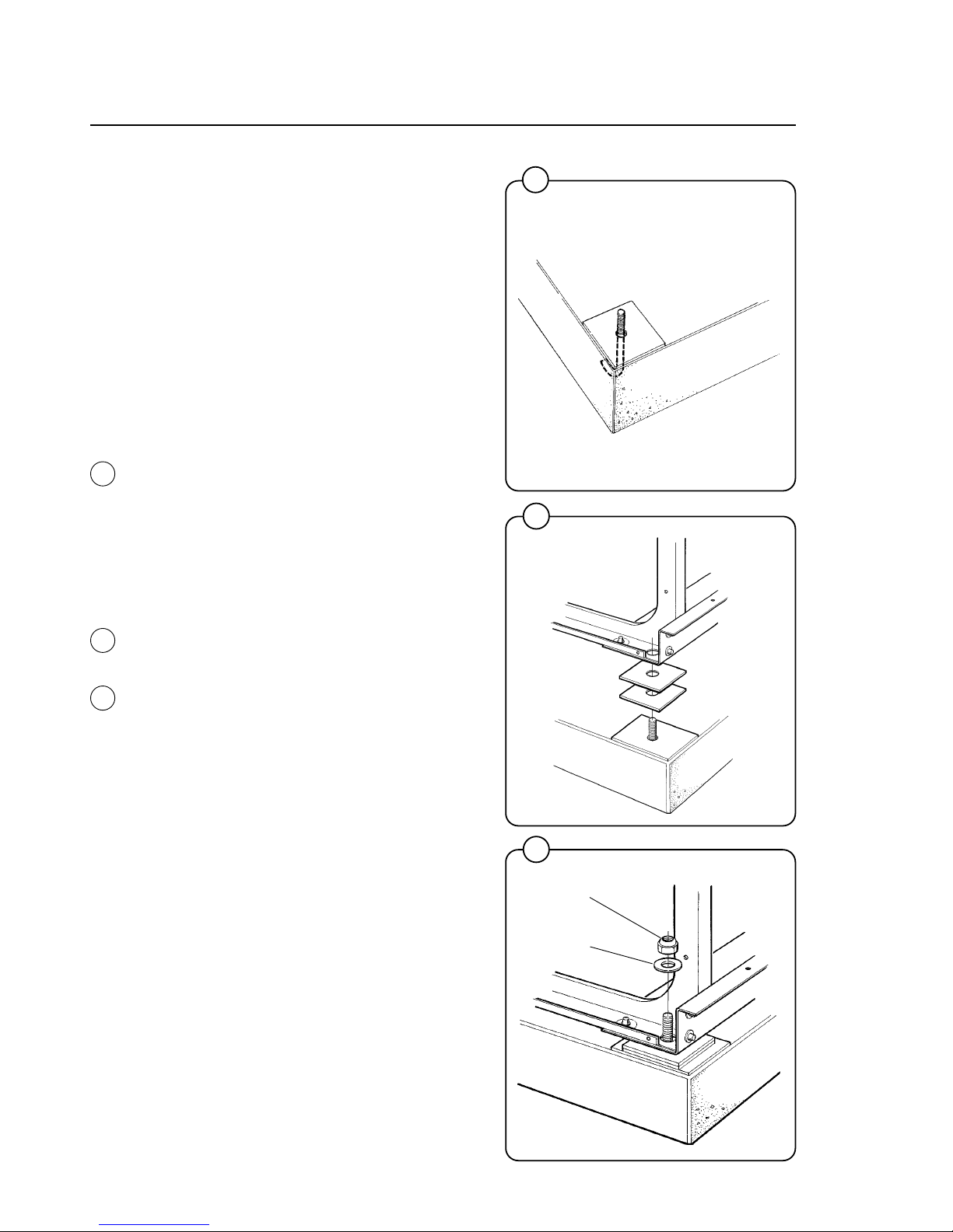
• Place flat washers over the foundation bolts
and secure the machine in position by tightening the self-locking nuts. See illustration
below.
• Check and tighten the nuts every week for the
first month.
selflocking
nut
flat washer
8
Fig.
5
Fig.
6
Fig.
7

9
Installation
10
1830
1838
1839
11
1137
Electrical Connections:
Although the machines are fitted with a thermal
overload in the motor windings, a separate threephase common-trip circuit breaker must be
installed for all three-phase machines.
For proper circuit breaker protection, check the
data plate at the rear of the machine. Also
consult local electrical code for special
requirements.
Connect L1, L2, L3 and ground wires according
to the markings of the terminal block. The cable
is to hang in a loose loop, supported by the clip
of the terminal block.
After installation, do the following:
Check the incoming power for any high voltage
leg by measuring voltage from each leg to ground. If a high leg is present, connect that line to
L2 on the terminal block, which goes to the motor
circuit.
Start the machine and check that the drum
rotates in the proper direction during extraction,
i.e. counter-clockwise when seen from the front.
If the drum rotates in the wrong direction switch
lines L1 and L3.
Check that the transformer on the control unit is
correctly tapped for the incoming voltage. The
different voltage alternatives are printed on the
transformer circuit board.
8
9
Fig.
8
Fig.
9
Fig.
10
Fig.
11
10
Installation
Water Connections:
NOTE
All plumbing must conform to national
and local plumbing codes.
Incoming water lines do not require non-return or
back flow prevention valves, as the machine is
already fitted with an approved siphon breaker.
However, all incoming lines must be fitted with
shut-off valves.
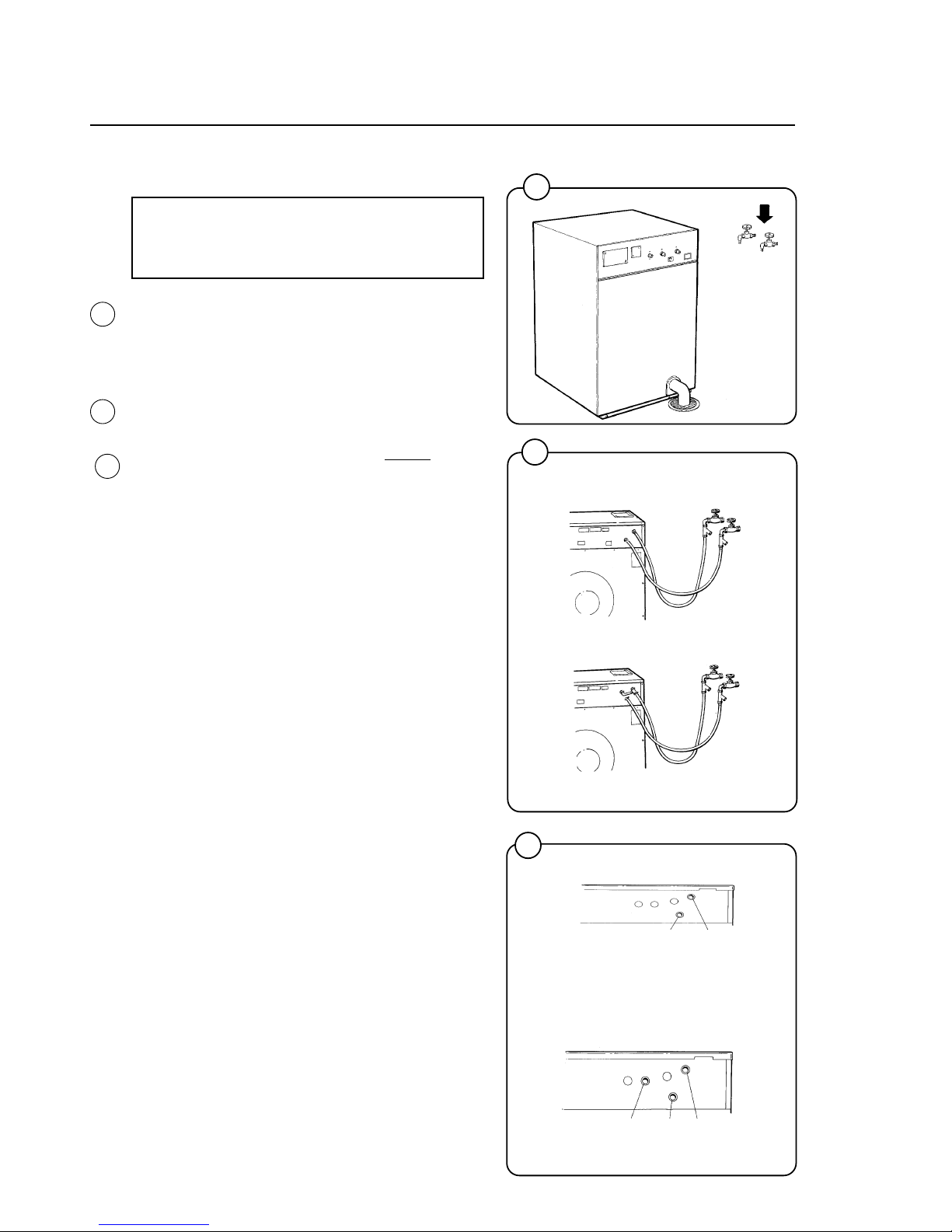
• Water inlets are labelled for hot and cold
water connection. The W185 has two hot
water and one cold water connections.
• Flush the water lines thoroughly
before
hooking hoses up to the washers, then check
that all water valves are attached tightly and
inlet screens not clogged. Use teflon pipe tape
if necessary to ensure watertightness.
• Use 1/2" or 3/4" diameter reinforced rubber
hosing not to exceed 6 feet in length. Let the
hoses hang in a loop. Do not use rigid piping.
Never force a hose onto the threads or you
may cause cross-threading and leaks. If this
occurs, place the threaded portion of the hose
over the valve threads and push forward
firmly, to catch the next thread. Then tighten.
Depending how large your laundry is, your
main incoming water line will generally be
between 1-1/2" to 3" diameter to assure
adequate water supply.
Fig.
12
Fig.
13
Fig.
14
12
13
1832
W 75, W105, W125
W 185
1870
14
hot water cold water
1846
W 75, W105, W125
W 185
hot water cold water cold water
(to detergent supply box)
1844

11
Installation
How to size water supply piping for Wascomat coin laundries
1. Calculate the total number of gallons of water that would be needed if all present (and
future) washers were to fill at the same time. Assume the W75 (18-lb.) uses 7 gallons
per fill; W105 (25-lb.) uses 10 gallons per fill; W125 (35-lb.) uses 14 gallons per fill‚
W185 (80-lb.) uses 20 gallons per fill; and W244 (75-lb.) uses 30 gallons per fill. If
water pipe runs of 70 feet or longer are required, multiply by 1.25 to compensate for
pipe friction which reduces flow rates.
2. Using the Flow Chart below and knowing the water pressure in the water main at your
store, select a pipe diameter that has a gallons per minute (gpm) flow rate the same or
higher than the total calculated above. The hot water line and the cold water line
supplying the washers must
each be this size diameter, since many fills are all hot or
all cold. This will assure fill times of approximately 1 minute and normal cycle times.
Wascomat washers are designed to operate at 25–85 PSI Call your local water utility
company if you do not know the water pressure in your water main.
GALLONS PER MINUTE FLOW CHART
Pipe internal Water pressure from the water main
Diameter, Inches 25 psi 40 psi 60 psi 80 psi
1/2 21 gpm 27 gpm 33 gpm 37 gpm
3/4 36 46 56 64
1 63 85 104 120
1-1/4 112 148 181 208
1-1/2 160 210 257 297
1-3/4 209 273 334 385
2 257 335 410 473
2-1/2 419 548 670 772
3 580 760 930 1070
3-1/2 650 840 1025 1185
4 720 920 1120 1300
5 1500 1960 2400 2770
6 1930 2530 3100 3580
3. The water line from the laundry to the water main in the street must carry
double the
total gallons capacity calculated in paragraph 1. Select the correct diameter from the
Flow Chart. (You will note from the chart that two 2'' pipes do
not equal the flow rate of
a 4 inch pipe; two 1'' pipes do
not equal the flow rate of a 2 inch pipe, etc... Use the
correct gpm flow rates!)
12
Drain Connections:
Connect a 3" (75 mm) flexible hose to the drain
outlet of the machine and clamp it securely.
The drain hose may be connected to a 2" to 3"
T- connection coming out of your main drain line,
which is typically four inches diameter, or the
washer may dump into a trough which slopes to
a drain, or directly into a floor drain as shown in
the illustration. Check local codes for required
installation procedure.
Start-up and safety checklist
Before initial start-up of a Wascomat washer the
following safety checks must be performed:
• Make sure the machine is properly bolted to
the floor and level.
• Make sure that all electrical and plumbing
connections have been made in accordance
with applicable local codes.
• Use only flexible water fill and drain hoses of
the proper length to avoid sags and kinks.
• Make sure the machine is properly grounded
electrically.
Installation
15
1833
16
1140
17
1834
Fig.
17
Fig.
16
Fig.
15
13
Installation
18
19
1853
1854
Fig.
18
Fig.
19
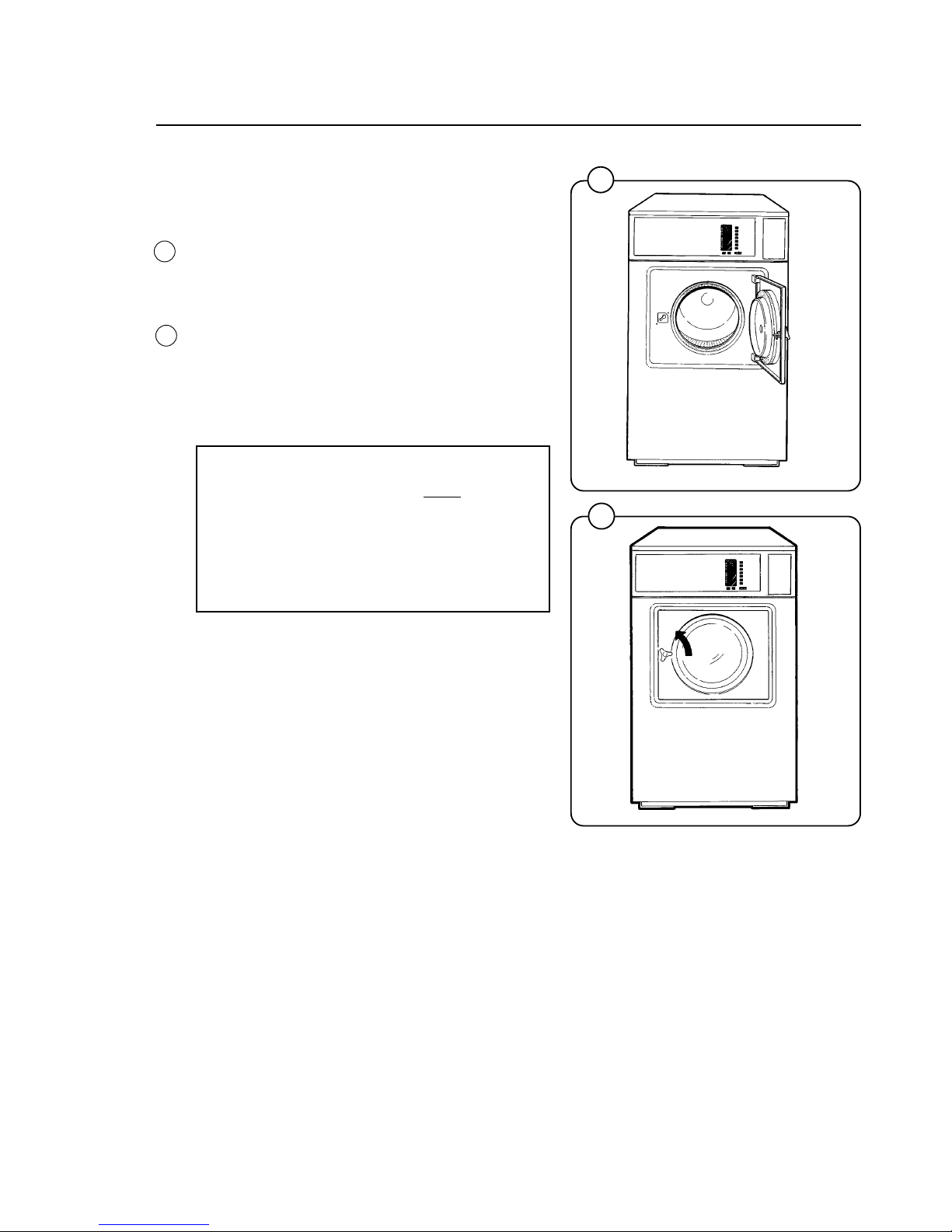
Before the machine is operated, the door lock
must be checked for proper operation as follows:
• When washer door is open, the machine must
not start. Verify this by attempting to start
washer with door open.
• When washer is in operation, the door is
locked and cannot be opened. Verify this by
attempting to open the door when the
machine is operating. If necessary, consult
this manual for proper operation of the door
lock or call a qualified serviceman.
IMPORTANT:
Door lock must be checked daily in
accordance with above procedure.
WARNING:
Before servicing Wascomat equipment,
disconnect electrical power.
If the side panels of the washer move during
extraction, remove the shipping security which
connects the top rear of the cylinder to the upper
section of the back panel. It is used to prevent
shipping damage but has no function when the
washer is installed in a laundry. In some rare
installations this bracket may transmit vibrations
to the side panels. If it does, remove the shipping
security; otherwise, leave it in place.

14
Installation
22
1295
1835
1836
23
0958
20
21
Fig.
20
Fig.
21
Fig.
22
Fig.
23
Function control check-out list
In the cylinder you will find the warranty registration card, a copy of the warranty policy, the bolthole template, wiring diagram, and other pertinent material. The warranty card must be completed and sent to Wascomat immediately or
your warranty coverage will start from the day we
shipped the washer from our warehouse. All
other items should be placed in a safe place for
future reference.
The machine should be cleaned when the installation is completed, and checked out as detailed
below without loading the machine with clothes:
1. Check the incoming power for proper voltage,
phase and cycles.
2. Open water taps to the machine.
3. Turn on electric power.
4. Check the door lock as detailed in this
manual.
5. Select the Warm cycle and then press the
START button.
6. Run through a complete Warm cycle, checking for proper water temperature, drain operation and extract direction. To rapid advance
the timer, press and hold down the START
button until the indicator arrows reach the
desired part of the cycle.
7. Now select and run the Cold cycle. There is
no hot water in the Cold cycle so if hot water
enters the hoses are improperly connected.
Reverse the hot and cold water hoses.
8. The drum must extract in a counter-clockwise
direction as seen from the front! If it does not,
reverse incoming electric lines L1 and L3.
NOTE:
All machines are factory tested prior to
shipment. Occasionally, some residual
water may be found when the machine is
installed.

15
2172
The keypad consists of seven wash program buttons, two option buttons
and a start button. An Information Display with illuminated symbols shows
the selected wash cycle, cycle options, steps in the wash cycle which have
been completed (indicated by squares around arrows), steps which remain
(indicated by arrows), remaining wash time, and the number of quarters
required to start the washer.
If a fault occurs then error numbers on the Information Display will refer you
to the fault code list under Fault Finding in this manual.
START
Extra
extract
Gentle
action
Hot
Warm
Cold
Delicate
Permanent Press
Quick - Wash
Heavy Soil
Heavy Soil
Prewash
Wash
Rinses
Final Extract
Extra Extract
Open door after
becomes
Add bleach
if desired
Rinse
Rinse
Add
softener
Fig.
24
24
Operating instructions
INFORMATION
DISPLAY
16
Operating Instructions
Preparations
Sort the wash according to the choices shown on
the control panel. Check washing tips on garment labels.
Make sure all pockets are empty and zips closed.
Load the washer and lock the door.
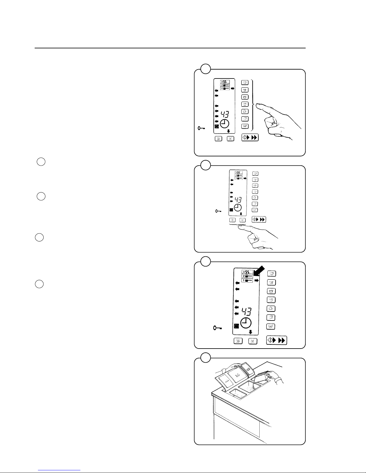
Washing
• Push one wash cycle button.
An arrow to the right of the control panel will
light up to show selection. Left arrows will light
to show the steps in the program.
• Select Extra Extract and/or Gentle Wash if
desired. Arrows will point to them.
• Three symbols in the Information Display
show in which compartments to put detergent
and softener.
- Prewash detergent in compartment 1.
- Mainwash detergent (and later bleach) in
compartment 2.
- Final rinse softener in compartment 3.
• You do not need more than 1/4 cup detergent
in a W75ES or W105ES, 1/3 cup in a
W125ES, or 1/2 cup in a W185ES.
0256
1302
1301
1300
Operating Instructions
Fig.
28
Fig.
27
Fig.
25
Fig.
26
25
26
27
28
 Loading...