

WARNING: ALL OPERATING AND MAINTENANCE PROCEDURES SHOWN ON THE NEXT
PAGE OF THIS MANUAL MUST BE FOLLOWED DAILY FOR PROPER OPERATION OF
YOUR WASCOMAT MACHINE.
PLEASE ENTER THE FOLLOWING INFORMATION AS IT APPEARS ON THE MACHINE(S)
DATA PLATE(S).
MAKE CERTAIN TO KEEP THIS MANUAL IN A SECURE PLACE FOR FUTURE
REFERENCE.
MACHINE TYPE OR MODEL
MACHINE SERIAL NUMBER(S)
ELECTRICAL CHARACTERISTICS:________ VOLTS, _______ PHASE, ______ HZ.
OPERATING & MAINTENANCE MANUAL
EX 7 ES – EX 10 ES
Emerald Series
471 1562-39/01
94.44

NOTICE TO: OWNERS, OPERATORS AND DEALERS OF WASCOMAT MACHINES
II
IMPROPER INSTALLATION AND INADEQUATE MAINTENANCE, POOR HOUSEKEEPING AND WILLFUL
NEGLECT OR BYPASSING OF SAFETY DEVICES MAY RESULT IN SERIOUS ACCIDENTS OR INJURY.
TO ASSURE THE SAFETY OF CUSTOMERS AND/OR OPERATORS OF YOUR MACHINE, THE FOLLOWING MAINTENANCE CHECKS MUST BE PERFORMED ON A DAILY BASIS.
1. Prior to operation of the machine, check to make certain that all operating instructions and
warning signs are affixed to the machine and legible. (See the following page of this manual
for description and location of the signs.) Missing or illegible ones must be replaced immediately. Be sure you have spare signs and labels available at all times. These can be obtained from your dealer or Wascomat.
2. Check the door safety interlock, as follows:
(a) OPEN THE DOOR of the machine and attempt to start in the normal manner:
For coin-operated models, insert the proper coins to start the machine.
For manually operated models, place the ON-OFF switch in the ON position and
press the Start switch.
For FL and EX models, insert a program card, turn the starter knob to the Start
position and place the ON-OFF switch in the ON position.
For HI-TEK microprocessor models, turn the key switch to the RUN position, choose
a program and press the START button.
For SELECTA 28 models, select a wash program and press the Start button.
THE MACHINE(S) SHOULD NOT START !
(b) CLOSE THE DOOR to start machine operation and, while it is operating, attempt to
open the door without exerting extreme force on the door handle. The door should
remain locked!
If the machine can start with the door open, or can continue to operate with the door
unlocked, the door interlock is no longer operating properly. The machine must be
placed out of order and the interlock immediately repaired or replaced.(See the door
interlock section of the manual.)
3. DO NOT UNDER ANY CIRCUMSTANCES ATTEMPT TO BYPASS OR REWIRE ANY OF
THE MACHINE SAFETY DEVICES AS THIS CAN RESULT IN SERIOUS ACCIDENTS.
4. Be sure to keep the machine(s) in proper working order: Follow all maintenance and
safety procedures. Further information regarding machine safety, service and parts can be
obtained from your dealer or from Wascomat through its Teletech Service Telephone - 516/
371-0700.
All requests for assistance must include the model, serial number and electrical characteristics as
they appear on the machine identification plate. Insert this information in the space provided on the
previous page of this manual.
5. WARNING: DO NOT OPERATE MACHINE(S) WITH SAFETY DEVICES BYPASSED, REWIRED OR
INOPERATIVE! DO NOT OPEN MACHINE DOOR UNTIL DRUM HAS STOPPED ROTATING!
CAUTION
1. Do not open washer door until cycle is completed, operating
light is off, and wash cylinder has stopped rotating.
2. Do not tamper with the door safety switch or door lock.
3. Do not attempt to open door or place hands into washer to
remove or add clothes during operation. This can cause
serious injury.
MACHINE SHOULD NOT BE USED BY CHILDREN
PRECAUCION
1. No abra la puerta de la máquina lavadora sino hasta que la
máquina haya terminado su ciclo, la luz operativa esté apaga
da y el cilindro de lavado haya completamento terminado de
girar.
2. No interferia o manipule el switch o la cerradura de la puerta.
3. No trate de abrir la puerta o meta las manos dentro de la
máquina para meter o sacar ropa mientras la máquina está
en operación, pues puede resultar seriamento herido.
LAS MÁQUINAS NO DEBEN SER USADAS POR NIÑOS
SAFETY AND WARNINGS SIGNS
Replace If Missing Or Illegible
One or more of these signs must be affixed on each machine as indicated, when not included as part of the front instruction panel.
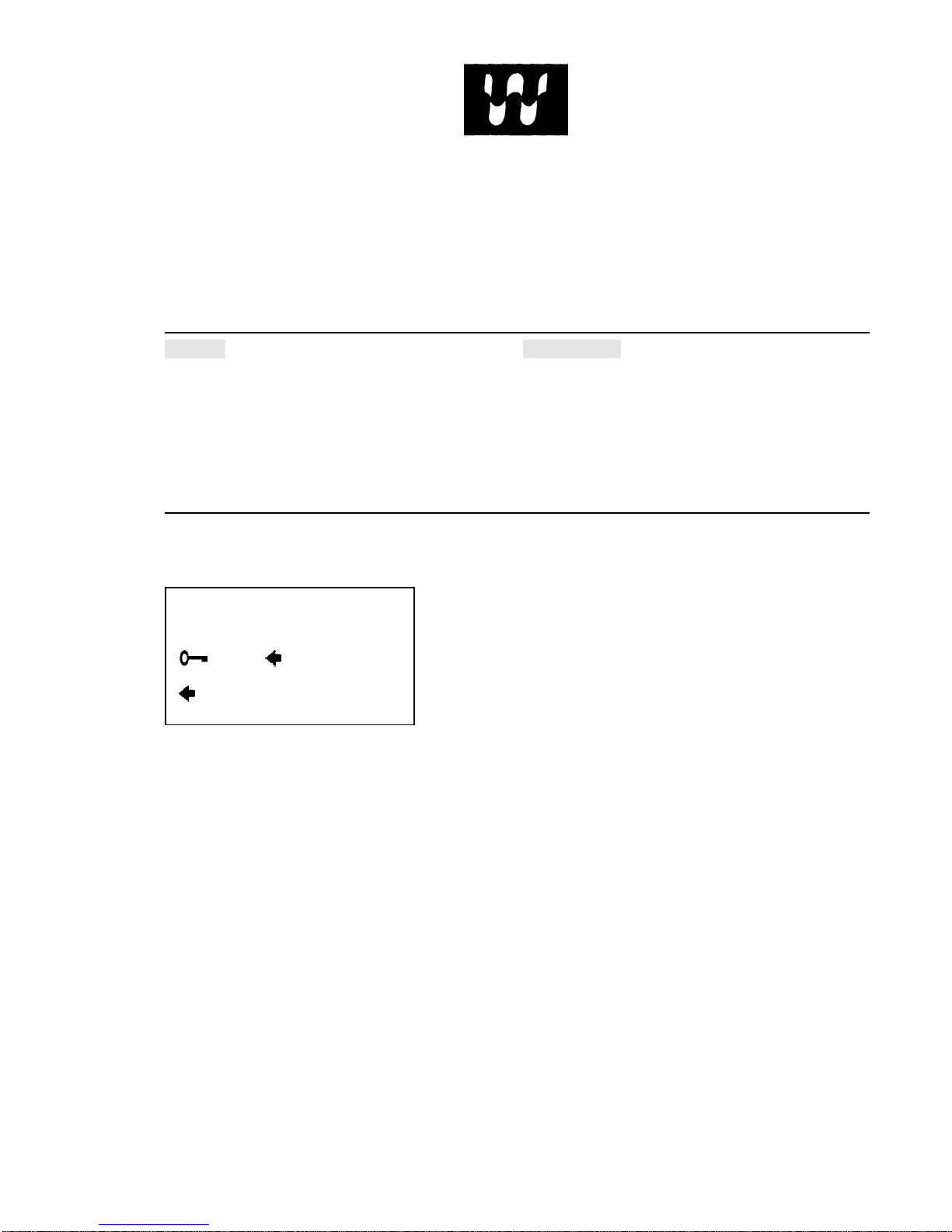
LOCATED ON THE OPERATING INSTRUCTION SIGN OF THE MACHINE:
LOCATED ON THE DOOR:
WARNING!
THE DOOR IS LOCKED A SHORT
WHILE AFTER THE SYMBOL AT
TURN TO
DOOR OPENING
– DRUM STAND STILL
–PRESS – PULL
471 7676-02
If you need to order more safety or warning
signs, call Wascomat's parts department at
516-371-2000, or call your local dealer.

Contents
Introduction ...................................................................... 1
Technical data.................................................................. 2
Installation........................................................................ 5
Safety rules ....................................................................11
Operating instructions .................................................... 12
Programming..................................................................17
Wash cycles................................................................... 21
Mechanical and electrical design ................................... 30
Maintenance...................................................................47
Trouble-shooting ............................................................48
Service information ........................................................ 53
Safety instructions
• This machine is designed for water washing only.
• This machine must not be used by children.
• All installation operations are to be carried out by qualified
personnel. Licensed personnel are necessary for all electric
power wiring.
• The interlock of the door must be checked daily for proper
operation and must not be bypased.
• All seepage in the system, due to faulty gaskets etc., must be
repaired immediately.
• All service personnel must be fully familiar with the operating
manual before attempting any repair or maintenance of the
machine.
• This machine must not be sprayed with water, otherwise short
circuiting may occur.
• Fabric softeners with volatile or inflammable fluids are not to
be used in the machine.
The manufacturer reservs the right to make changes to design and
material specifications.
EX7, EX 10
1
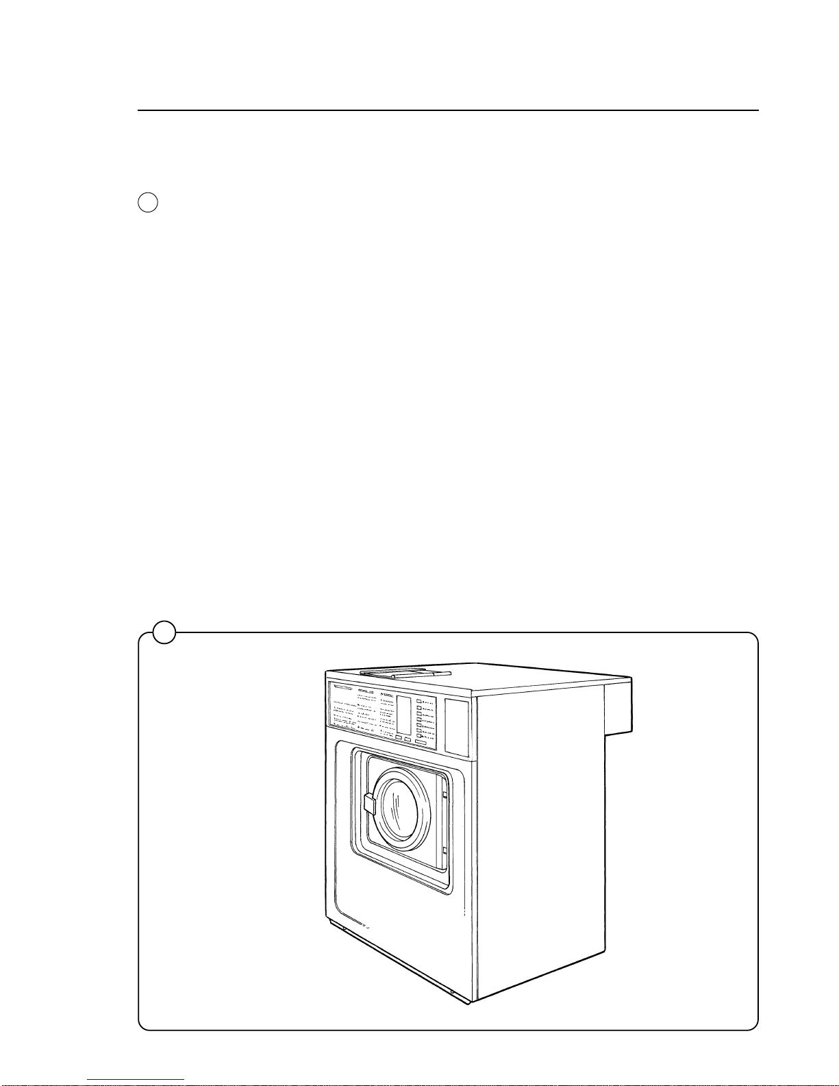
Introduction
Introduction
The EX 7 and EX 10 Emerald models washer/extractor with high spin
speeds, have been developed to meet the needs of state-of-the-art professional laundromats, institutions, hospitals etc., where high quality automatic washing and quick formula variation are required.
Emerald models are unique because you can program different prices for
the seven wash cycles, giving the customer a real choice and allowing you
to maximize revenue by changing what each cycle is worth. In addition, you
can charge a higher price if the customer selects the Extra Extract option.
Using an external clock and wiring harness, these models may be programmed to lower the price by any percentage between any hours of any
days, for the ultimate in pricing flexibility!
The machines are free-standing, i.e. the drum is free to move relative to the
frame of the machine, being suspended from it by springs. This results in a
considerable reduction in vibration transferred to the frame of the machine,
which in turn simplifies installation: no special foundation is required.
The seven cycles offer different water temperatures, wash times, extraction
times, and normal or gentle drum rotation. EMERALD SERIES washers
achieve maximum environmental efficiency because only the minimum
amount of water is used for each cycle, which vary in duration.
When ordering spare parts or contacting Wascomat or your dealer for
service, always give the machine serial number, model, voltage and other
electrical characteristics appearing on the data plate at the top left of the
rear panel of the machine. The serial number is also printed on a sticker
inside the door...
KEEP THIS MANUAL IN A SAFE PLACE FOR FUTURE REFERENCE!
1821
1
Fig.
1

Technical data
2
Technical data EX 7
Dry load capacity up to 15 lbs
Overall dimensions Width 720 mm 28 11/32 in
Depth 660 mm 26 in
Height 1100 mm 43 5/16 in
Net weight 164 kg 361 lbs
Maximum floor load 1.64 ± 0.7 kN 390 ± 170 lbs force
Crated dimensions Volume 0.66 m
3
23.3 cu.ft
Weight 176 kg 387 lbs
Inner drum dimensions Diameter 520 mm 20 15/32 in
Depth 310 mm 12 3/16 in
Volume 60 litre 2.1 cu.ft
Drum speed Wash 52 rpm
Distribution 80 rpm
Extraction 1020 rpm
G-factor During wash 0.8
During extraction 300
Motor speed During wash 1140 rpm
During distribution 1740 rpm
During extraction 3430 rpm
Voltage requirements 120 V 1-Phase 60 Hz
Rated output power Motor, wash 140 W 0.19 HP
Motor, distribution 100 W 0.13 HP
Motor extraction 350 W 0.5 HP
Overcurrent protection 20 A
Water connections Rec. pressure 2-6 kp/cm
2
25-85 psi
Hose connection, water DN 20 3/4 in
Drain connection Hose 50 mm 2 in

Technical data
3
Technical data EX 10
Dry load capacity up to 25 lbs
Overall dimensions Width 720 mm 28 11/32 in
Depth 820 mm 32 9/32 in
Height 1100 mm 43 5/16 in
Net weight 225 kg 495 lbs
Maximum floor load 2.3 ± 0.9 kN 550 ± 220 lbs force
Crated dimensions Volume 0.77 m
3
27.2 cu.ft
Weight 240 kg 528 lbs
Inner drum dimensions Diameter 520 mm 20 15/32 in
Depth 470 mm 18 1/2 in
Volume 100 litre 3.5 cu.ft
Drum speed Wash 52 rpm
Distribution 80 rpm
Extraction 1020 rpm
G-factor During wash 0.8
During extraction 300
Motor speed During wash 1130 rpm
During distribution 1730 rpm
During extraction 3400 rpm
Voltage requirements 120 V or 208-240 V 1- Phase 60 Hz
Rated output power Motor, wash 200 W 0.27 HP
Motor, distribution 180 W 0.24 HP
Motor extraction 550 W 0.74 HP
Overcurrent protection 20 A at 120 V
15 A at 208-240 V
Water connections Rec. pressure 2-6 kp/cm
2
25-85 psi
Hose connection, water DN 20 3/4 in
Drain connection Hose 50 mm 2 in
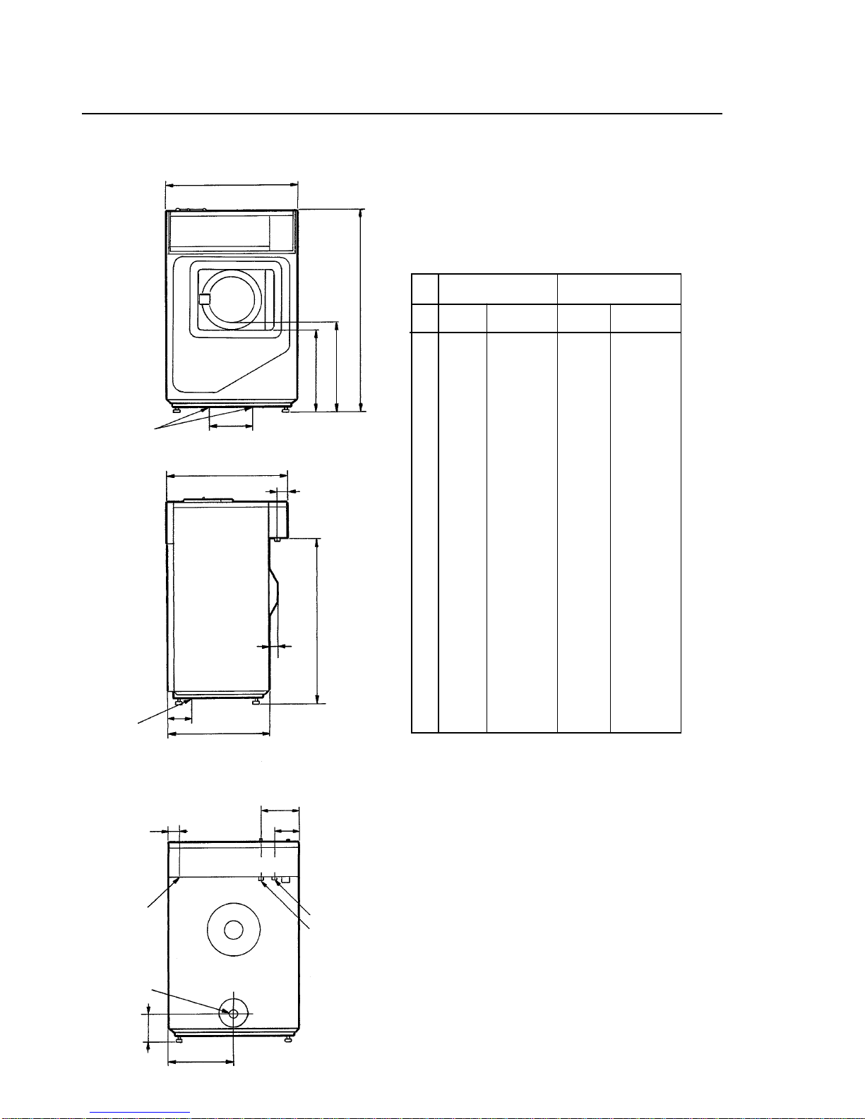
Outline and dimension
Technical data
EX 7 EX 10
mm inches mm inches
A 1100 43 5/16 1100 43 5/16
B 485 19 3/32 485 19 3/32
C 440 17 5/16 440 17 5/16
D 260 10 1/4 260 10 1/4
E 720 28 11/32 720 28 11/32
F 660 26 820 32 9/32
G 65 2 9/16 65 2 9/16
H 555 21 27/32 715 28 5/32
J 50 1 31/32 50 1 31/32
K 905 35 5/8 905 35 5/8
L 40 1 9/16 40 1 9/16
M 60 2 3/8 60 2 3/8
N 210 8 9/32 210 8 9/32
O 130 5 1/8 130 5 1/8
P 360 14 5/32 360 14 5/32
R 150 5 29/32 150 5 29/32
4
C
B
A
E
D
F
G
H
J
K
L
N
O
M
P
R
Drain
Electrical
connection
Mounting
holes
Mounting
holes
Hot water
Cold water
1596
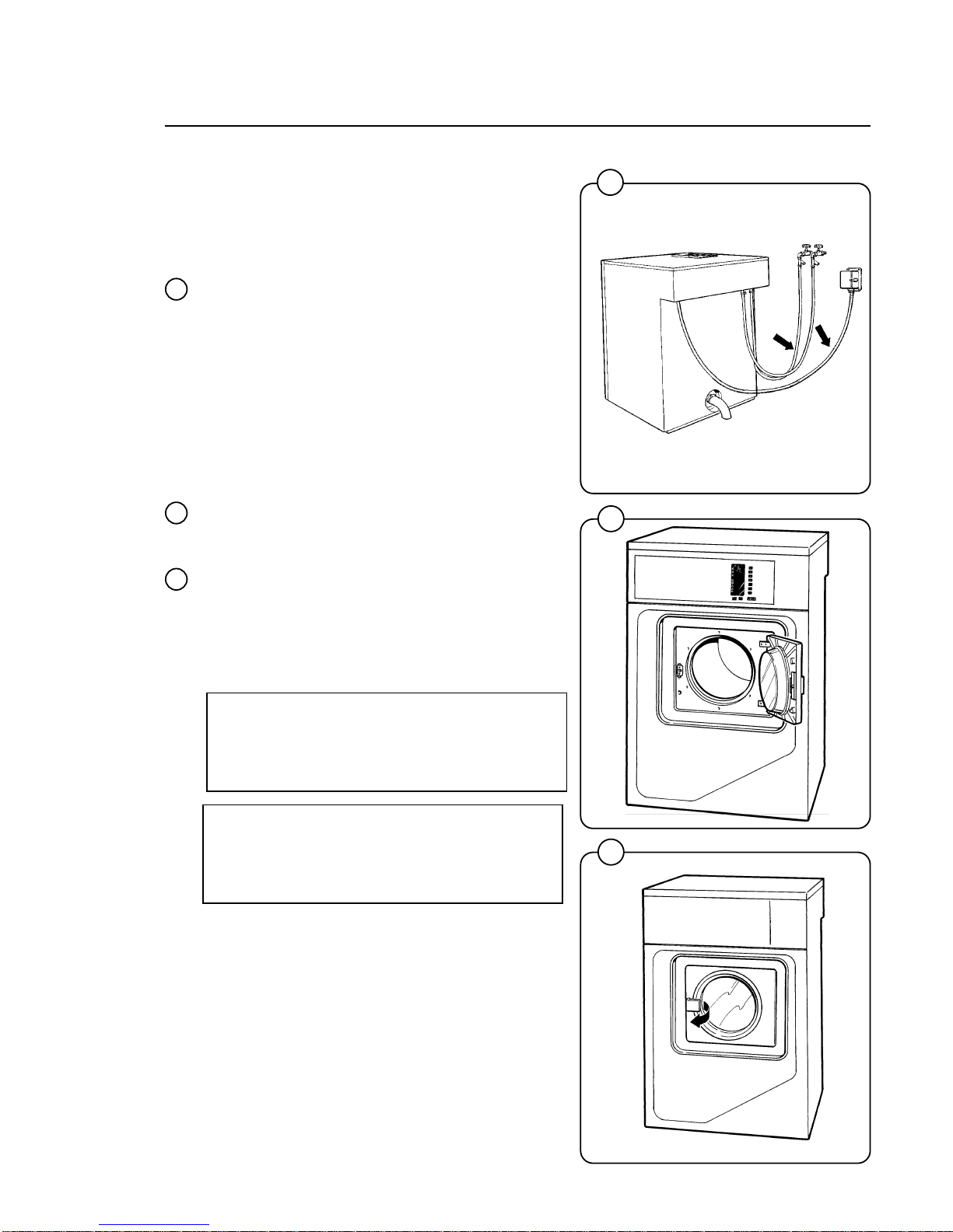
Installation
2
0243
Installation
The machines are free-standing, i.e. the drum
can move relative to the frame of the machine.
This results in a considerable reduction in vibration transferred to the frame which in turn
simplifies installation: no special foundation is
required.
The machine is delivered complete with expansion bolts, template etc. packed inside the drum.
Move the machine on its pallet to where it is to be
installed before removing the pallet retaining
bolts.
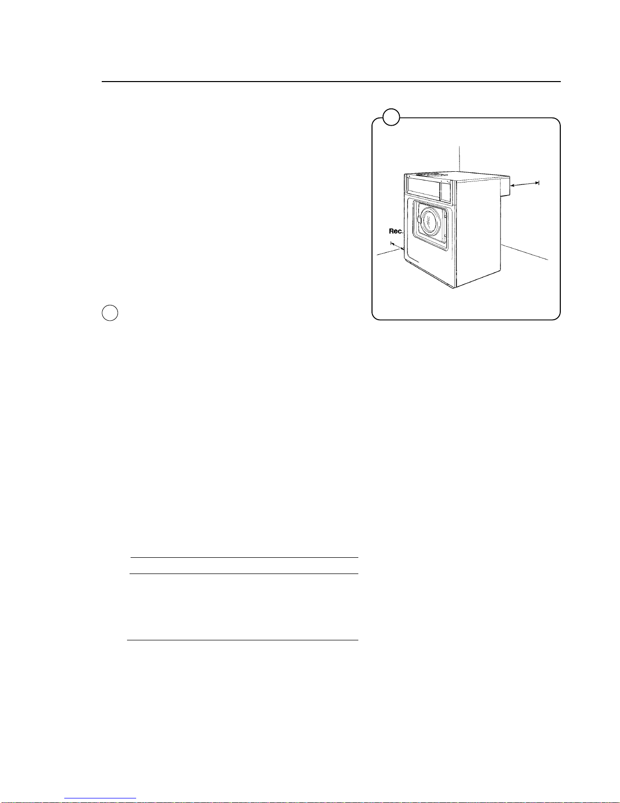
Location
Install the machine close to a floor drain or open
drain.
In order to make installation and servicing the
machine easier the following clearances are
recommended:
• At least 20" between the machine and the wall
behind
• and a minimum of 2" on both sides of the
machine whether installed next to the wall or
other machines.
Where space is limited it is possible to reduce
this distance to a minimum of 1" at the rear and
sides, since most service operations are carried
out from the front or top of the machine.
Floor
The floor must be able to withstand the following
loads:
EX7 EX10
static 390 lbs 550 lbs
dynamic 170 lbs 220 lbs
frequency of 17 kHz 17kHz
dynamic force
5
20"
2"
Fig.
2
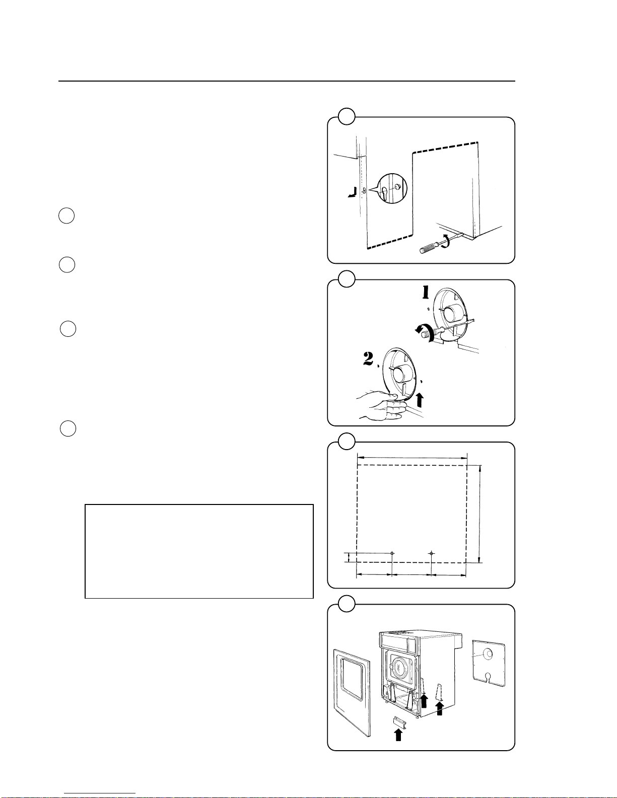
Installation
Mechanical installation
The machine is delivered with the drum locked in
place by four transport bolts fitted between the
frame and the drum. In orderto remove these
and install the machine, proceed as follows:
• Unpack the machine.
• Slacken off the screws in the lower edge of
the front cover plate and remove the plate by
pulling downward and outward to unhook it
from the chassis.
• Unscrew the retaining screws on the rear
plate and remove the plate. Remove the
drainage connection by unscrewing the two
screws. Lift the drainage connection upwards
until comes loose from the rear plate.
• Mark and drill two holes (diameter =5/16")
about 4" deep in the positions shown.
• Remove the machine from the transport pallet.
Fit the adjustable feet provided.
• Place the machine above the bolt holes you
just drilled. Always lift the machine by the
chassis, never by the door or door handle.
• Remove the four transport bolts securing the
drum to the chassis.
• Check that the machine is level and steady.
Adjust the level by using the four adjustable
feet (check first that they are screwed in as far
as possible). Lock the feet using the lock nuts
when the machine is satisfactorily positioned.
NOTE!
It is of utmost importance that the
machine be level, from side- to- side as
well as front- to- rear. If the machine is not
properly leveled, it may result in a false
out-of-balance cutout.
• Insert the expansion bolts supplied in the
holes drilled in the floor.
Fit the washers and nuts, and tighten well.
After the machine has been in use for a while
check and retighten the nuts if necessary.
3
4
5
6
0674
0244
0672
0671
6
EX 7
EX 10
720 mm
65mm
230mm
260mm
230mm
2 9/16 in
9 1/16 in
10 1/4 in
9 1/16 in
28 11/32 in
EX10:
820mm
32 9/32 in
EX7:
660mm
26 in
Fig.
3
Fig.
4
Fig.
5
Fig.
6
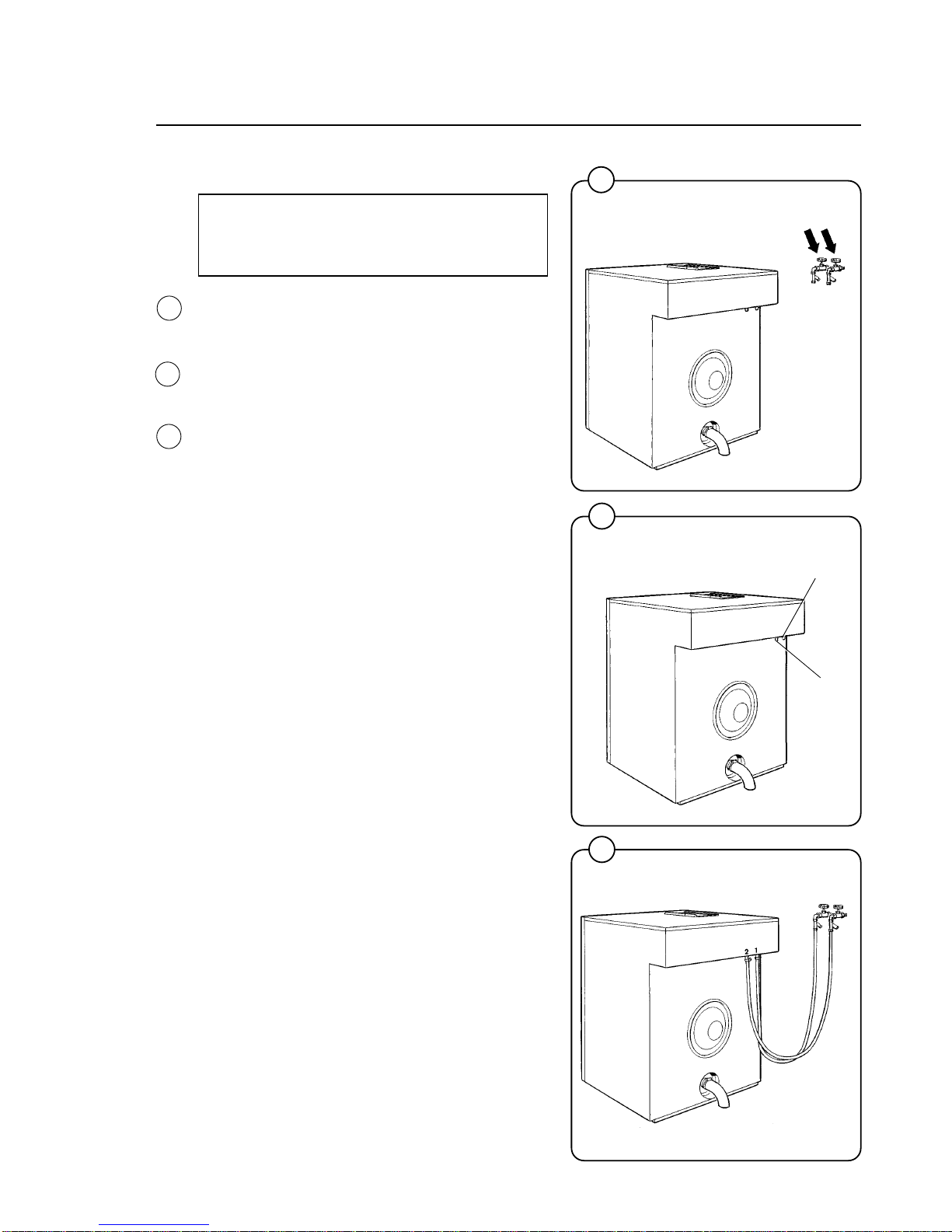
Installation
Water supply
NOTE
All plumbing must conform to national
and local plumbing codes.
The water supply to the machine should be fitted
with manual shut-off valves to facilitate installation and servicing.
Water inlets are labelled for hot and cold water
connections. Hoses should be flushed through
before being connected to the machine.
Connection hoses should be 3/4" reinforced
rubber hosing not to exeed 6 ft in length. Make
sure the hoses have no sharp bends or angles.
Water pressure should be:
maximum: 142 psi (10 kp/cm
2
)
recommended: 25-85 psi (2-6 kp/cm
2
)
7
7
8
9
0248
1597
1598
Cold water
Hot water
Fig.
7
Fig.
8
Fig.
9
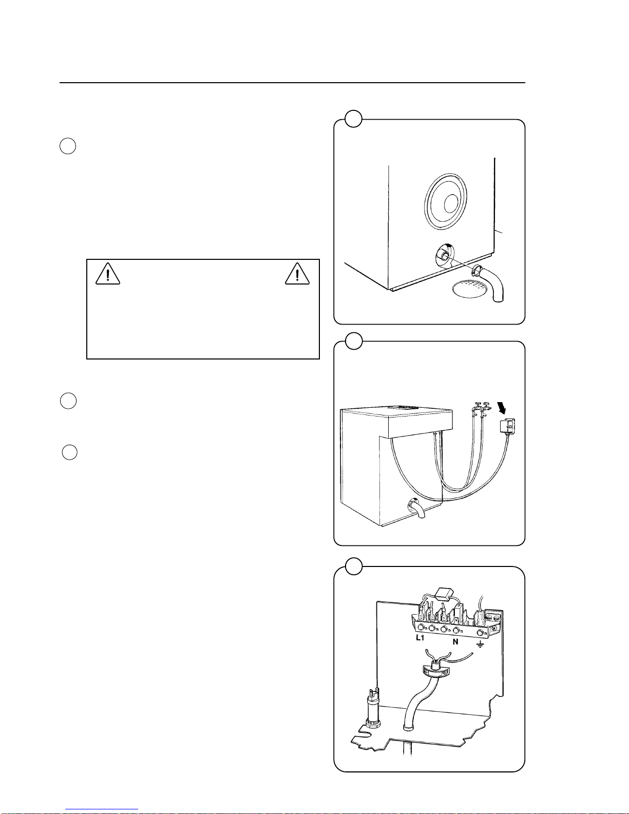
Drain connection
Connect a 50 mm (2") flexible hose to the
machine’s drain outlet. Avoid sharp bends which
may prevent proper draining.
The drainage pipe should be located over a floor
drain, drainage channel or similar so that the
distance between the outlet and the drain is at
least 25 mm (1"). Refer to local regulations on
watersupply and drainage.
Electrical installation
Electrical installation must be carried out
by an authorized electrician, and must
follow national and local regulations.
Make sure that the ground wire is
correctly connected.
Each machine must be connected through its
own circuit breaker.
The cable must hang in a gentle arc.
Installation
0057
8
1599
10
11
Fig.
10
Fig.
11
Machines connected for 1 AC
2189
12
Fig.
12
13
14
Installation
15
1600
1602
1820
Start-up and safety checklist
Before initial start-up of a Wascomat washerextractor, the following safety checks must be
performed:
• Make sure that all electrical and plumbing
connections have been made in accordance
with applicable local codes.
• Use only flexible water fill and drain hoses of
the proper length to avoid sags and kinks.
• Make sure the machine is properly grounded
electrically.
Before the machine is operated, the door safety
interlock must be checked for proper operation
as follows:
• When washer loading door is open, the
machine must not start. Verify this by
attempting to start washer with door open.
• When washer is in operation, the loading door
is locked and cannot be opened. Verify this by
attempting to open the loading door when the
machine is operating. If necessary, consult
this manual for proper operation of the door
lock and door safety interlock or call a
qualified serviceman.
IMPORTANT:
Door safety interlock must be checked daily
in accordance with above procedure.
WARNING:
Before servicing Wascomat equipment,
disconnect electrical power.
Fig.
13
Fig.
14
Fig.
15
9

1822
16
Function control check-out list
In the machine cylinder, you will find the warranty
registration card, a copy of the warranty policy
and other pertinent material.
The warranty card should be completed and sent
to Wascomat. All other items should be placed in
a safe place for future reference.
The machine should be cleaned when the
installation is completed, and checked out as
detailed below without loading the machine with
fabrics:
1. Check the incoming power for proper voltage,
phase and cycles.
2. Open manual shut-off valves to the machine.
3. Turn on electric power.
4. Check the door safety interlock as detailed on
page 10 of this manual.
5. Select the HOT program and start the
machine.
6. Run through a complete cycle, checking for
water temperature, drain operation and the
extract function.
7. In the wash cycle only hot water should enter.
If cold water comes in, the hoses are
improperly connected. Reverse hot and cold
water hoses.
NOTE
All machines are factory tested prior to
shipment. Occasionally, some residual
water may be found when the machine is
installed.
Installation
Fig.
16
10
17
Fig.
17
HOT
Time Temp.
(Min.)
Prewash 3 Warm
Detergent 1
Drain 0.8
Mainwash 6 Hot
Detergent 2
Drain 0.8
Extraction 0.5
Rinse 1 1 Warm
Drain 0.8
Extraction 0.5
Rinse 2 1 Cold
Drain 0.8
Extraction 0.5
Rinse 3 2 Cold
Detergent 3
Drain 1
Extraction 4
Shake-out 0.5
Total time 23
(water fill time
not included)
1203

Safety rules
• This machine is designed for water washing only.
• Machines must not be used by children.
• All installation operations are to be carried out by qualified personnel.
Licensed personnel are necessary for all electric power wiring.
• The interlock of the door must be checked daily for proper operation
and must not be bypassed.
• All seepage in the system, due to faulty gaskets etc., must be repaired
immediately.
• All service personnel must be fully familiar with the operating manual
before attempting any repair or maintenance of the machine.
• This machine must not be sprayed with water, otherwise short circuiting
may occur.
• Fabric softeners with volatile or inflammable fluids are not to be used in
this machine.
Safety Rules
11
12
2172
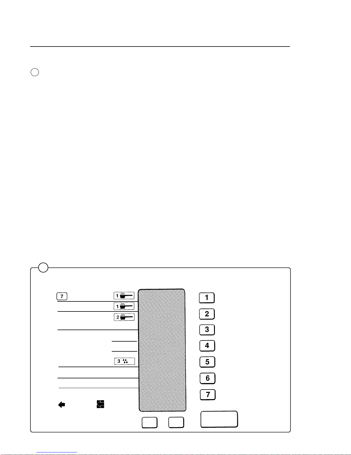
Operating instructions
The keypad consists of seven wash program button, two option buttons and
a start button. An Information Display with illuminated symbols shows the
selected wash cycle, cycle options, steps in the wash cycle which have
been completed (indicated by squares around arrows), steps which remain
(indicated by arrows), remaining wash time, and the number of quarters
required to start the washer.
If a fault occurs then error numbers on the Information Display will refer you
tot he fault code list under Fault Finding in this manual.
START
Extra
extract
Gentle
action
Hot
Warm
Cold
Delicate
Permanent Press
Quick - Wash
Heavy Soil
Heavy Soil
Prewash
Wash
Rinses
Final Extract
Extra Extract
Open door after
becomes
Add bleach
if desired
Rinse
Rinse
Add
softener
INFORMATION
DISPLAY
18
Fig.
18
13
Operating Instructions
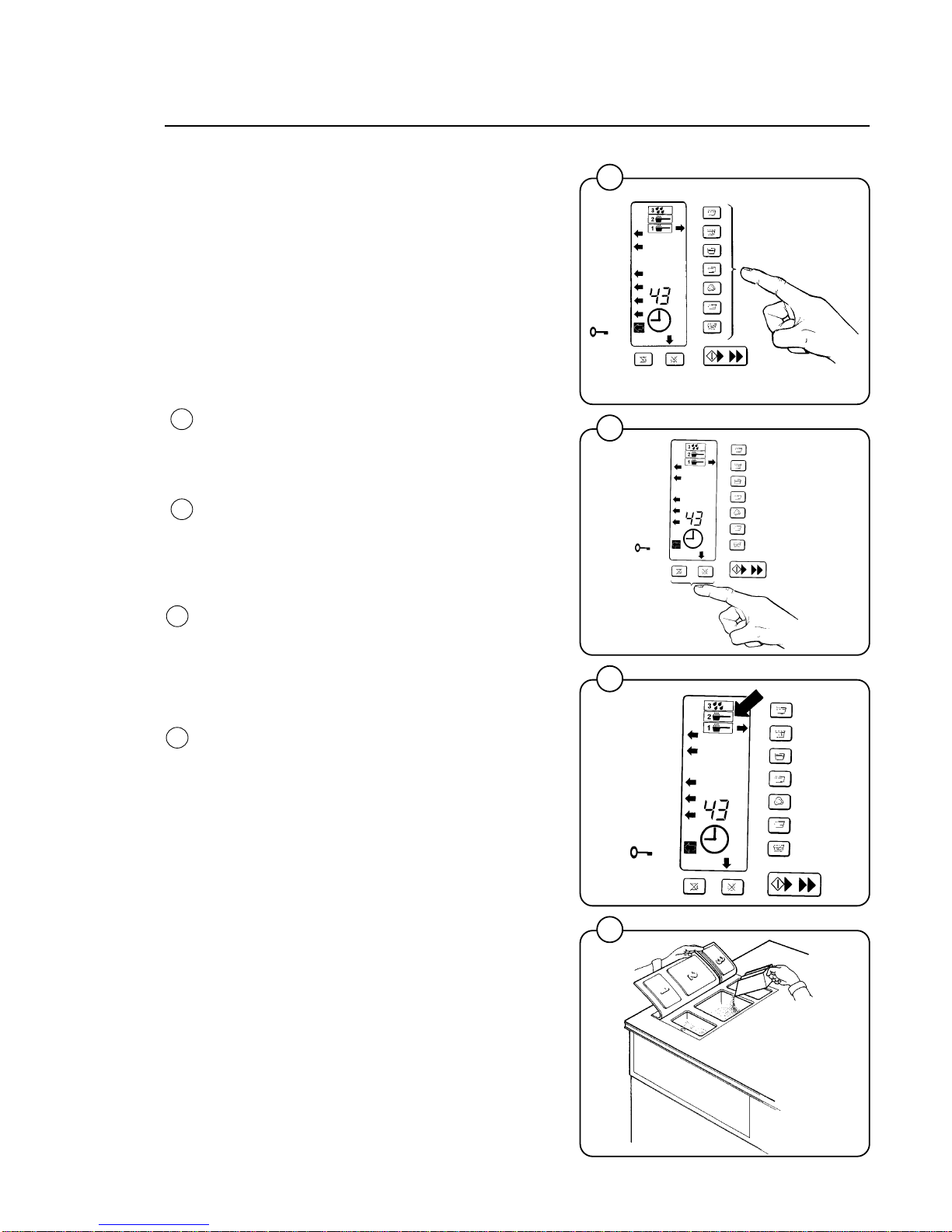
Operating Instructions
Preparations
Sort the wash according to the choices shown on
the control panel. Check washing tips on garment labels.
Make sure all pockets are empty and zips closed.
Load the washer and lock the door.
Washing
• Push one wash cycle button.
An arrow to the right of the control panel will
light up to show selection. Left arrows will light
to show the steps in the program.
• Select Extra Extract and/or Gentle Wash if
desired. Arrows will point to them.
• Three symbols in the Information Display
show in which compartments to put detergent
and softener.
- Prewash detergent in compartment 1.
- Mainwash detergent (and later bleach) in
compartment 2.
- Final rinse softener in compartment 3.
• You do not need more than 1/4 cup detergent
in a EX7 ES or EX10 ES..
0256
1302
1301
1300
Fig.
22
Fig.
21
Fig.
19
Fig.
20
19
20
21
22
14
Operating Instructions
1303
1022
1020
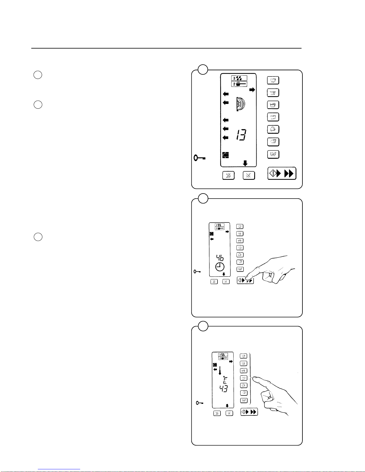
Insert required number of quarters as shown
on the display, which counts down quarters as
they are inserted. Press START button when
the display shows 00.
A clock symbol will now appear and remaining
wash time in minutes counts down. (The time for
each cycle will not be displayed until the cycle
has been run once completely from beginning to
end, so the microprocessor knows how long it
should take). The microprocessor retains in
memory how long it took to run each cycle the
last five times and displays the average time.
Since water pressure may fluctuate affecting fill
times, the displayed average cycle time is not
always exact and may vary from machine to
machine. If you find cycle times taking longer and
longer, use that information as a warning that
your water inlet screens may be clogged,
extending fill times, or some other problem may
exist.
Figure 25 illustrates a temperature display
function only available on washers with built-in
heating, which are not used in North America.
Fig.
23
Fig.
24
Fig.
25
24
23
25
 Loading...