

Page 1

OFFICIAL W ARWICK
AMP OWNER MANUAL
ENGLISH
Page 2

Amps
4
Congratulations on the purchase of the
new Warwick amplifier head/combo.
Please read these instructions through before
connecting and operating the device.
If you keep to the guidelines set out in this manual,
you will soon be able to appreciate the quality of
this new Warwick amplifier. Please keep this
instruction booklet handy in case you need to
consult it again.
Please send the PASSPORT to the address
indicated therein.
The following recommendations are designed to
ensure that the device always functions reliably:
Never open the casing! To do so would expose
you to the risk of an electric shock. Should repairs
prove necessary, leave them to qualified service
personnel.
Avoid dust and high moisture levels, direct
sunlight and extremely high or low temperature.
Safeguard the device from excessive vibration.
Always place the unit on a stable and horizontal
surface.
See to adequate ventilation. The device should not
be placed on soft surfaces (carpet, cushions, etc.).
When mounting it in a rack, make sure that the
rear and lateral cooling vents remain unobstructed
(amp heads), resp. that the rear cooling vents
remain unobstructed (combos).
Avoid leaving the unit near radiators or other
objects producing heat.
Internal components should only be adjusted or
cleaned by qualified service technicians.
Ensure no object or liquid penetrates the device
through its cooling vents.
When replacing a fuse make sure you fit in
one of identical value!
Have the device examined by a qualified service
technician in the following cases:
- the mains lead or mains switch have been
damaged,
- objects or liquids have penetrated the device,
- it has been exposed to excessive moisture,
- malfunctions or abnormal operating conditions
have occurred,
- the device has been dropped or the casing
damaged.
RECOMMENDATIONS
To ensure secure rac k or sleeve mounting you will
find two nuts on the bottom side of the amplifier
for additional fastening (all amp heads).
Do only operate effects pedals in-between the
instrument and the amplifier, as these devices
are not designed for the supplied load of an
effects loop.
Each W-Pro unit has been conceived to match
perfectly as a system-component within this series.
Therefore best sound results can be achieved by
mutual combination of these devices.
Many combinations are possible and allow
gradual upgrading of several high-quality systems
within different performance scales and for almost
every kind of application.
HINTS
-Remove the plug whenever changing a fuse.
- Only ever replace a fuse with another of the
same type. Never bridge defective fuses.
- Make sure the top and bottom of the device are
properly ventilated and that the vents are not
blocked. In the rack, leave at least 2cm free above
the unit and do not remove the feet.
-Do not subject the device to excessive vibration
or hard jolts as these could damage the valves
("tubes").
- After using the device, allow around 10 minutes
for the valves to cool down before moving it.
-At power-up, the valves (tubes) need at least 30
seconds to warm up before achieving operation
readiness and a further few minutes before they
can deliver full power.
- When changing the valves, replace them only
with valves selected by Warwick, to avoid
problems like noise, microphonism and
imbalance. (special selection criteria).
-Valves can become very hot. Danger of
combustion.
-Don't undertake repairs yourself.
- Only allow the case to be opened by qualified
personnel. (Remove the plug).
-Repairs and valve changes should only be
undertaken by qualified personnel.
Page 3
Pro Tube IX
23
GROUND LIFT switch isolates the earth
connection from the ground of signal. Should
several devices be simultaneously connected to
earth by the same conductor as well as via line
connections, a so called hum loop might appear. In
this case operate GROUND LIFT to eliminate the
current hum.
DI PRE/POST switches the signal lying at the DI
OUT sockets.
PRE the unmodified bass signal is retained on
both DI OUT sockets,
POST the tone control and effects loops are
inserted into the signal path in stereo.
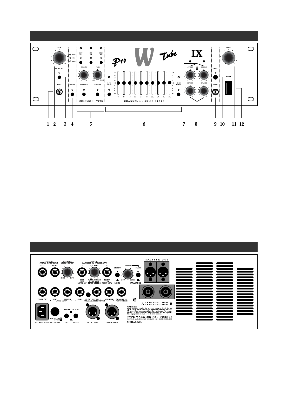
REAR PANEL
1. INPUT socket to plug in a bass guitar.
2. GAIN control + 3 LE Ds to adjust the input
level: CLIP too high,
OK optimum,
LOW too low.
3. CH. SELECT + 2-colored LED to switch from
channel 1 (red) to channel 2 (green).
4. LIMITER switch + 2-colored LED to
compress the signal (channel 2 only):
green Limiter on,
red the signal level is actually
bein reduced.
5. For features of CHANNEL 1, please refer to
the chapter CHANNEL 1-TUBE.
6. For features of CHANNEL 2, please refer to
the chapter CHANN EL 2-SOLI D STATE.
7. OUTPUT control for each channel + OL
(overload) LED to mutually balance both
channel levels. Should the OL LE D light up,
reduce OUTPUT of the respective channel.
The standard setting, i.e. with neither
attenuation nor amplification, is position 8
(when tone controls are set linearly).
8. EFF. MIX controls determine the degree to
which the effects within the parallel stereo loop
(rear panel) affect the signal of each channel.
9. PHONES socket for connecting a headphone
(min 200 Ω).
10. MUTE switc h + red LED cuts the signal from
all outputs, except from the PHONES socket,
and activates the TUNER output (rear panel).
11. MASTER control determines the mains level.
12. POWER switch for turning the amplifier on
and off.
FRONT PANEL CONTROLS
Page 4

24
Pro Tube IX
DI OUT LEFT and DI OUT RIGHTsockets for
supplying a stage or studio mixing console.
TUNER OUT socket for the connection of a tuner.
When MUTE mode is activated, the unmodified
bass signal is retained here.
MONO LOOP for the serial insertion of dynamic
effects units (e.g. compressor, auto wah, etc.).
Connect SEND with the input and RETURN with
the output of the effects device.
PARALLEL STEREO LOOP: the degree to
which external effects influence the signal can be
determined with the EFF. MIX control located on
the front panel. Connect SEND with the input and
RETURN L. and RETURN R.with the outputs of
the effects device.
LO CUT switch confines the SEND output to
frequencies above 200 Hz. Modulation effects (e.g.
chorus) remain clear this way.
Note:
You can also use the RETURN sockets as LINE INs
in case you wish to operate the amplifier as a power
amp. To this purpose rotate the EFF. MIX controls
on the front panel to their full clockwise positions.
CHANNEL 1/2 FOOTSWITCH allows to
connect a footswitch for selecting between both
channels. To do so use a switch (latch) and not a
key (unlatch).
SPEAKER OUT sockets designed to supply
loudspeaker cabinets. Each channel of the 2 x 450
watts power amplifier provides respectively one
XLR and one Speakon socket in parallel. The
signal from the Speakon outputs is leaded by 1+
and 1-.
LINE OUT PARALLEL TO SPEAKER OUT
sockets allow to connect additional power
amplifiers.
BIAMP/FULLRANGE switches over between
two operation modes of the power amplifier. In
FULLRANG E mode the whole frequency range
is provided by both SPEAKER OUT sockets. In
BIAM P mode the signal is splitted by an active
crossover.
X-OVER control sets the transition frequency
between 80 Hz and 4 kHz.
STEREO/MONO switch to use the amplifier
whether in stereo or in mono.
The combination of BIAMP and STEREO
switch settings give access to different operation
modes. Signal splittings at the respective sockets
are as follows:
SPEAKER OUT A,
LINE OUT PARALLEL TO SPEAKER OUT A,
called "A" hereafter;
SPEAKER OUT B,
LINE OUT PARALLEL TO SPEAKER OUT B,
called "B" hereafter;
LINE OUT STEREO BIAMP HIGH - LEFT
and RIGHT, called HIGH L and HIGH R
hereafter, are shown in the following chart:
Balances can be determined with the respective
BALANCE controls. The right one acts on the
outputs A and B (LINE OUTs and S PEAKER
OUTs), whereas the left one regulates between
low and high frequencies in STEREO BIAMP
mode. In this operation mode whether external
power amplifiers with cabinets or active
loudspeakers must be connected to the
LINE OUT STEREO BIAMP HIGH sockets.
IMPORTANT:
The BALANCE STEREO BIAMP CONTROL
should be centered or pointing to the right-
hand range in the operation modes monofullrange, mono biamp and stereo fullrange,
OTHERWISE NO SIGNAL WILL BE SENT
TO A AND B, RESPECTIVELY THE INPUT
LEVEL AT THE POWER AMPLIFIER WILL
BE TOO LOW.
Mode A B HIGH L HIGH R
Fullrange Mono Fullrange Fullrange no signal no signal
Left und Right Left und Right
Fullrange Stereo Fullrange Fullrange no signal no signal
Left Right
BiAmp Mono High Low no signal no signal
Left und Right Left und Right
BiAmp Stereo Low Left Low Right high left high right
Page 5

Pro Tube IX
25
This channel is equipped with two tubes. One
preamp tube is always included within the signal
flow.
2ND STAGE switch adds one output stage tube
into the circuit. This feature offers the choice
between a so called hybrid amplifier (tube preamp
with transistor power amp) and the sound of an all
tube amplifier head.
CONTOUR switch boosts bass and treble at once.
CRUNCH control adjusts the tube pre-
amplification.
TONE control sets the basic sound c haracteristics
(frequency control 300 Hz - 14 kHz, see below).
LOW B/C 3-way switch for the boost/flat/cut of
sub-bass frequencies. In boost position (red LED)
the bottom-end is boosted, in cut position (yellow
LED) it remains unmodified, but the deep-mids
region is attenuated to obtain a clearer sound
(chords, tapping, harmonics, etc.).
MID B/C 3-way switch for the boost/flat*/cut of
the frequency determined via TONE control. In
boost position (red LED) this frequency is boosted,
in cut position (yellow LED) it is attenuated.
* The respective frequency will be slightly boosted
when the switch is centered (flat). All boosts and
attenuations are less intense in deeper frequency
ranges than in higher spectra (300 Hz +6/+12 dB,
14 kHz +1 5/+20 dB, flat/boost).
HIGH B/C 3-way switch to boost/flat/cut high
sound attributes. In boost position (red LED)
treble is boosted (fixed preset), in cut position
(yellow LED) the TONE control works as a lowpass-filter, means that frequencies higher than the
TONE control setting are eliminated. Moreover
the MID-boosts are softened by about 5 dB.
As you can see, the three 3-way switches and
TONE control act in a very complex way.
Therefore I would like to introduce some remarks
and suggestions regarding sound adjustments:
1. Simulation of different pickup characteristics:
Each pickup has a peak in its resonance frequency
in excess of which no treble can be transmitted.
The main distinction in sound characteristics
between different pickups is that this frequency is
located elsewhere depending on pickup types. This
is exactly what you can simulate in switch positions
MID boost and HIGH cut by shifting the
resonance frequency with the TONE control
(12 o'clock until full clockwise position). This
requires that the resonance frequency of your bass
pickups lies beyond that of the desired simulation.
Furthermore this adjustment allows to boost
highest trebles that your bass can produce, by
cutting even higher pitches so as to diminish
unnecessary noise.
2. Speaker Emulator (when CRUNCH is driven
highly until distortion):
In case you have adjusted a distorted sound with
the CRUNCH control and use a loudspeaker
cabinet with tweeter (or send the sound via the
DI OUTs to a mixer), you should eliminate highpitched frequencies with HIGH cut, as they can be
very unpleasant for the human ear. When
MID boost is activated at the same time, the sound
will be more aggressive, whereas the simultaneous
use of MID cut results in a smooth but however
deeper cut of treble (see graph).
If necessary you can turn the TONE control
further clockwise.
CHANNEL 1 - TUBE
3. Semi-parametric EQ:
When the MID 3-way switch is set to boost, flat
(center position, slight boost) or cut, you can preadjust the basic timbre of your sound with the
TONE control like with a semi-parametric filter.
As already mentioned, the degree of boosts or cuts
depends on frequency ranges. These have been
determined so as to obtain efficient results by quick
adjustment.
Page 6

26
Pro Tube IX
EXAMPLES
These setting examples aim at helping you to
better handle with the control stage and to utilise
it for the realisation of your sound conceptions. Set
channel 1 according to the examples and adjust
the TONE control to the left and to the right
within the suggested area, respectively. press the
switches to learn more about their efficiency.
CRUNCH settings are level-dependent. The
examples suppose GAIN has been set to OK. As
Rock-parts are usually performed harder than
tapping-techniques, rather than compensating for
this gap with GAIN to obtain the desired
compression, you could just raise the CRUNCH
control in this case.
1
1 1
CRUNCH
0
2
4
6
8
10
12
TONE
2ND STAGE
CONTOUR
LOW
B/C
MID
B/C
HIGH
B/C
CHANNEL 1 - TUBE
LOW HIGH
1
1 1
CRUNCH
0
2
4
6
8
10
12
TONE
2ND STAGE
CONTOUR
LOW
B/C
MID
B/C
HIGH
B/C
CHANNEL 1 - TUBE
LOW HIGH
1
1 1
CRUNCH
0
2
4
6
8
10
12
TONE
2ND STAGE
CONTOUR
LOW
B/C
MID
B/C
HIGH
B/C
CHANNEL 1 - TUBE
LOW HIGH
1
1 1
CRUNCH
0
2
4
6
8
10
12
TONE
2ND STAGE
CONTOUR
LOW
B/C
MID
B/C
HIGH
B/C
CHANNEL 1 - TUBE
LOW HIGH
1
1 1
CRUNCH
0
2
4
6
8
10
12
TONE
2ND STAGE
CONTOUR
LOW
B/C
MID
B/C
HIGH
B/C
CHANNEL 1 - TUBE
LOW HIGH
1
1 1
CRUNCH
0
2
4
6
8
10
12
TONE
2ND STAGE
CONTOUR
LOW
B/C
MID
B/C
HIGH
B/C
CHANNEL 1 - TUBE
LOW HIGH
1
1 1
CRUNCH
0
2
4
6
8
10
12
TONE
2ND STAGE
CONTOUR
LOW
B/C
MID
B/C
HIGH
B/C
CHANNEL 1 - TUBE
LOW HIGH
1
1 1
CRUNCH
0
2
4
6
8
10
12
TONE
2ND STAGE
CONTOUR
LOW
B/C
MID
B/C
HIGH
B/C
CHANNEL 1 - TUBE
LOW HIGH
Tapping/chords
2ND STAGE
CONTOUR
TONE S. PICTURE
CRUNCH S. PICT.
LOW
MID
HIGH
ON
ON
CUT
BOOST
FLAT
Ballade
2ND STAGE
CONTOUR
TONE S. PICTURE
CRUNCH S. PICT.
LOW
MID
HIGH
ON
OFF
BOOST
BOOST
CUT
Hollow Reggae
2ND STAGE
CONTOUR
TONE S. PICTURE
CRUNCH S. PICT.
LOW
MID
HIGH
OFF
ON
BOOST
CUT
CUT
Clear compress
2ND STAGE
CONTOUR
TONE S. PICTURE
CRUNCH S. PICT.
LOW
MID
HIGH
OFF
OFF
FLAT
FLAT
BOOST
Clean Funk
2ND STAGE
CONTOUR
TONE S. PICTURE
CRUNCH S. PICT.
LOW
MID
HIGH
OFF
ON
FLAT
BOOST
FLAT
Hard Funk
2ND STAGE
CONTOUR
TONE S. PICTURE
CRUNCH S. PICT.
LOW
MID
HIGH
ON
ON
BOOST
CUT
BOOST
Straight Rock
2ND STAGE
CONTOUR
TONE S. PICTURE
CRUNCH S. PICT.
LOW
MID
HIGH
ON
OFF
BOOST
FLAT
FLAT
Fat and ugly
2ND STAGE
CONTOUR
TONE S. PICTURE
CRUNCH S. PICT.
LOW
MID
HIGH
ON
ON
BOOST
BOOST
CUT
Page 7

Pro Tube IX
27
Two switches LOW BOOST and HIGH BOOST
to pre-adjust the basic sound characteristics.
Ten faders
35/70/140/210/420/730/1.2k/2.5k/5k/10k Hz
to amplify/soften the respective frequency
band by +/-12 dB.
You should generally adjust the graphic E Q to
approximately 0 dB. This means boosts and cuts
should be effected with moderation.
When adjusting the faders mostly within the
positive area (1) the OL LED of the master
section might illuminate, which means you
enter the overload range before the master
control. In this case reduce OUTPUT from
channel 2. If the LIMITER is activated and
threshold appears too high, readjust the EQ
curve to lower levels (2). Reducing GAIN
would result in a worse S/N ratio and can
eventually not be recommended. Should you
find the threshold is too low, i.e. more intense
compression is desired, shift the EQ curve
further to the positive area.
CHANNEL 2 - SOLID STATE
+12
+9
+6
+3
0dB
-3
-6
-9
-12
.
.
.
.
.
.
.
.
.
.
.
.
.
.
.
.
.
.
.
.
.
.
.
.
.
.
.
.
.
.
.
.
.
.
.
.
.
.
.
.
.
.
.
.
.
.
.
.
.
.
.
.
.
.
.
.
.
.
.
.
.
.
.
.
.
.
.
.
.
.
.
.
.
.
.
.
.
.
.
.
.
+12
+9
+6
+3
0dB
-3
-6
-9
-12
2
2
LOW
BOOST
CHANNEL 2 - SOLID STATE
HIGH
BOOST
35 70 140
210
420
730
1,2k 2,5k
5k
10k
+12
+9
+6
+3
0dB
-3
-6
-9
-12
.
.
.
.
.
.
.
.
.
.
.
.
.
.
.
.
.
.
.
.
.
.
.
.
.
.
.
.
.
.
.
.
.
.
.
.
.
.
.
.
.
.
.
.
.
.
.
.
.
.
.
.
.
.
.
.
.
.
.
.
.
.
.
.
.
.
.
.
.
.
.
.
.
.
.
.
.
.
.
.
.
+12
+9
+6
+3
0dB
-3
-6
-9
-12
2
2
LOW
BOOST
CHANNEL 2 - SOLID STATE
HIGH
BOOST
35 70 140
210
420
730
1,2k 2,5k
5k
10k
12
1. Make sure that loudspeakers capable of sustaining
the load of a bass signal are connected to the
SPEAKER OUT sockets. The speaker cables
should meet a cross-section of at least 2 x 1.5 mm.
2. Check that the mains supply has been plugged
in and that all external (effects) units possibly
used are correctly connected and operational.
3. Select the mode in which you wish to operate
(Fullrange/BiAmp, Mono/Stereo).
4. Set the MASTER control to zero.
5. Plug your bass guitar into the amplifier's
INPUT with a shielded line-cable.
6. Press the POWER switch to turn the device on.
7. Switch MUTE off and the red LED will
extinguish. (Should the CH. SELECT switch
be set to channel 1, it will take a few seconds
before a signal can be processed, as the tubes
must be heated first.)
8. T urn all volume controls of your bass guitar on
to their maximum.
9. Adjust the GAIN control until the (loudly)
played bass signal illuminates the OK LED.
10.Set both OUTPUT controls to their
positions 8.
11. Set the MASTER control to the volume you
wish to play at.
12.Adjust the controls and switches of both
channels according to your sound conceptions.
If it appears necessary, reduce OUTPUT again
with the appropriate controls. The OL LED
might actually flash only occasionally, but it
should not remain permanently lit.
13. Balance the levels from one channel to another
with the OUTPUT controls and set the EFF.
MIX of the parallel stereo loop for both
channels to regulate the amount of effects
within the signal path.
14. If necessary readjust balances on the
rear panel.
IMPORTANT:
Make sure that gain of the elected louder channel
is correctly determined and occasionally
illuminates the OL LED, as either full power can
actually not be used (level set too low), or
undesired distortions might appear (level set too
high).
GETTING STARTED
Page 8

28
NOTES
Pro Tube IX
Page 9

30
Amps
Pro Fet III
25 mV
transistor, active
controlled
none
fan cooled (non
permanent)
bass, punch,
param. mids with
freq. and level
controls, attack,
treble, low boost
and high
boost switches.
Dyn. control with
switchable limiter
none
200 Ω
0 dB, 600 Ω
mono serial
send 0 dBu, 600 Ω
return 0 dBu, 10 kΩ
ground lift,
DI pre/post
none
none
250 W/4Ω jack
XLR & Speakon
<0.1%
11,5
19“/48 3x90x375
Pro Fet IV
25 mV
transistor, active
controlled
none
fan cooled (non
permanent)
3-way switches for
low boost/flat/cut
mid boost/flat/cut
high boost/flat/cut
param.freq.contr.,
8-band graph. EQ
+/-12 dB,
dyn.contr. with
switchable
limiter (3-way)
none
200 Ω
0 dB, 600 Ω
mono serial
send 0 dBu, 600 Ω
return 0 dBu, 10 kΩ
ground lift,
DI pre/post
none
graph. EQ on
400 W/4Ω jack
XLR & Speakon
<0.1%
12,5
19“/48 3x90x375
Pro Tube IV
25 mV
transistor, active
controlled
dual tube
fan cooled (non
permanent)
3-way switches for
low boost/flat/cut
mid boost/flat/cut
high boost/flat/cut
param.freq.contr.
contour switch,
dyn. control with
2nd tube and
crunch control.
8-band graph. EQ,
+/- 12dB, switches
for low boost and
high boost.
Dyn. control with
switchable limiter
200 Ω, stereo
2x0 dB, 600 Ω,
stereo or 2x mono
stereo serial
send 0 dBu, 600 Ω
return 2x0dBu,
10kΩ
ground lift,
DI pre/post
none
CH 1 /2
400 W/4Ω jack
XLR & Speakon
<0.1%
15,0
19“/48 3x90x4 30
Pro Tube IX
25 mV
transistor, active
controlled
dual tube
fan cooled (non
permanent)
3-way switches for
low boost /flat/cut
mid boost/flat/cut
high boost /flat
/cut param.
freq.contr.,contour
switch,
dyn. control with
2nd tube and
crunch control.
10-band graph.
EQ, +/- 12dB,
switches for low
boost and high
boost. Dyn.
control with
switchable limiter
200 Ω, stereo
2x0 dB, 600 Ω,
stereo or 2x mono
mono serial
send 0 dBu, 600
Ω return
0dBu,1 0kΩ
stereo parallel,
send fullrange or
200 Hz low cut,
same values
ground lift,
DI pre/post,
stereo, biamp, low
cut
X-over,
2x balance
CH 1 /2
2x450 W/4Ω jack
XLR & Speakon
<0.1%
22,3
19“/483x135x455
Sonic II / III
25 mV
transistor, active
controlled
none
fan cooled (non
permanent)
bass, mid low, mid
high, treble
controls, low boost
and high boost
switches
none
200 Ω
mono serial
send 0 dBu, 600 Ω
return 0 dBu, 10 kΩ
DI pre/post
none
none
II: 200 W/ 4Ω
III: 300 W/4Ω
<0.1%
II: 8,3 ; III: 10,7
500x90x285
Quad IV / VI
25 mV
all tube
none
fan cooled
(temperature
controlled)
Quadrumatrix
bass, mid 1 (+shift),
mid 2 (+shift),
treble, low boost
and high boost
switches
none
200 Ω, stereo
0 dB, 600 Ω
mono parallel
send 0 dBu, 600 Ω
return 0 dBu, 10 kΩ
ground lift,
DI pre/post
Effects mix
none
IV: 400 W/4Ω
VI: 600 W/4Ω
<0.1%
IV: 15,0 ; VI: 16,5
483x90x430
Page 10

42
CIRCUIT DIAGRAM
Pro Tube IX
Page 11

Headquarters:
Warwick GmbH&Co.Music Equipment KG•Gewerbegebiet Wohlhausen•08258 Markneukirchen/Germany•Tel 0049-(0)37422-555-0
Fax 0049-(0)37422-555-99 • Send us an E-Mail to: info@warwick.de • Visit us on the World Wide Web: http://www.warwick.de
Branch China:
Warwick Music Equipment (Shanghai) Ltd., Co.Shanghai Waigaoqiao Free Trade Zone • Shanghai 200131 / P.R.China
 Loading...