

Warsanis 1401FM Quick Installation And Setup Manual

WARSANIS 1401FM USER MANUAL
QUICK INSTALLATION AND SETUP MANUAL
WARSANIS
MODULATION PROCESSOR
March 2001
MODEL 1401FM
Wijde Wade 5
3439 NP Nieuwegein
The Netherlands
Tel. 31 (0)30 2322209
Fax. 31 (0)30 2304959
EMAIL. info@warsanis.nl
http://www.warsanis.nl
1

WARSANIS 1401FM USER MANUAL
Manual Rev.2.2
Part number: M1401FM0397
8/2001 Warsanis Productions.
2

WARSANIS 1401FM USER MANUAL
TABLE OF CONTENTS
P age Contents
1 Table of contents
2 Table of contents, continued
3 Warranty
Introduction
4,5 Short description of the Warsanis 1401FM
6 Installation General
Installation in the studio
Installation at the transmitter site
7 Changing the input sensitivity
Analog Inputs and outputs
Phase rotator
Analog Output level
Baseband Composite outputs
Baseband Composite output level
Changing the composite output impedance
8 SCA Input
19kHz output
19kHz crystal oscillator
Unbalanced analog usage
Grounding
Fuses
9 Setup and operation
Preparation
Line up
Composite STL link
10 Using SCA
11 Density switches
Stereo Tracking
Loudness clipping
Transmitter limiters / clippers
12 Recommended settings
3

WARSANIS 1401FM USER MANUAL
TABLE OF CONTENTS, CONTINUED
P age Contents
13 The Warsanis 1401FM in harmony with other equipment
Mic processing
Leveler
Other effect equipment
Stereo enhancers
Equalizers
Audio exciters
Bass enhancers
14 Test and alignment procedures
Power-up test
Input stage test
Phase rotator test
Leveler test
15 Crossover test
Multiband test
Multiband clipping test
16 Loudness clipping test
Output stage test
Stereo Generator test
17 Troubleshooting
Lost of modulation
Buzz
Whistle
Gross distortion or lost of modulation
If on-air balance seems incorrect
18 Check the four band processors
Vocal distortion
Gate light permanent on or off
If you still have a problem
19,20 Technical specifications general
21 Technical specifications stereo generator
23 Boards
25 Stereo Generator
4
WARSANIS 1401FM USER MANUAL
WARRANTY
Warsanis Productions warrants its products to be free from any defects in
workmanship for a period of one year. This warranty will not be void if the user
modifies a Warsanis product. However, broken wires, broken PC board circuit traces,
burned areas and broken components resulting from improper procedures/ handling
are not covered under warranty. Warsanis Productions is not responsible for damages resulting from the use of its product, from incorrect or unsafe installation, or for
damages caused by war, fire, flood or other man made or natural calamites.
Please fill in the Registration Card and fax it to Warsanis Productions in The
Netherlands. You are then automatically entered in our product update en new
product mailing list.
INTRODUCTION
The Warsanis 1401FM is an integrated multiband audio processing system for FM
radio that replaces all others compressors, limiters, clippers, the stereo generator
and filters. It can be installed either at the studio site using the analog stereo outputs
or the transmitter site using the composite outputs. It can also be used for a composite baseband microwave link. It is possible with the Warsanis 1401FM to create your
own sound with an absolute control of peak modulation. You can vary your sound
between unprocessed and heavily processed. With the Warsanis 1401FM you can
give your station the punch, loudness and clarity you always wanted. The Warsanis
1401FM does not only do a great job for CHR stations but also sounds perfectly for
talk radio and AC music formats and even clasical.
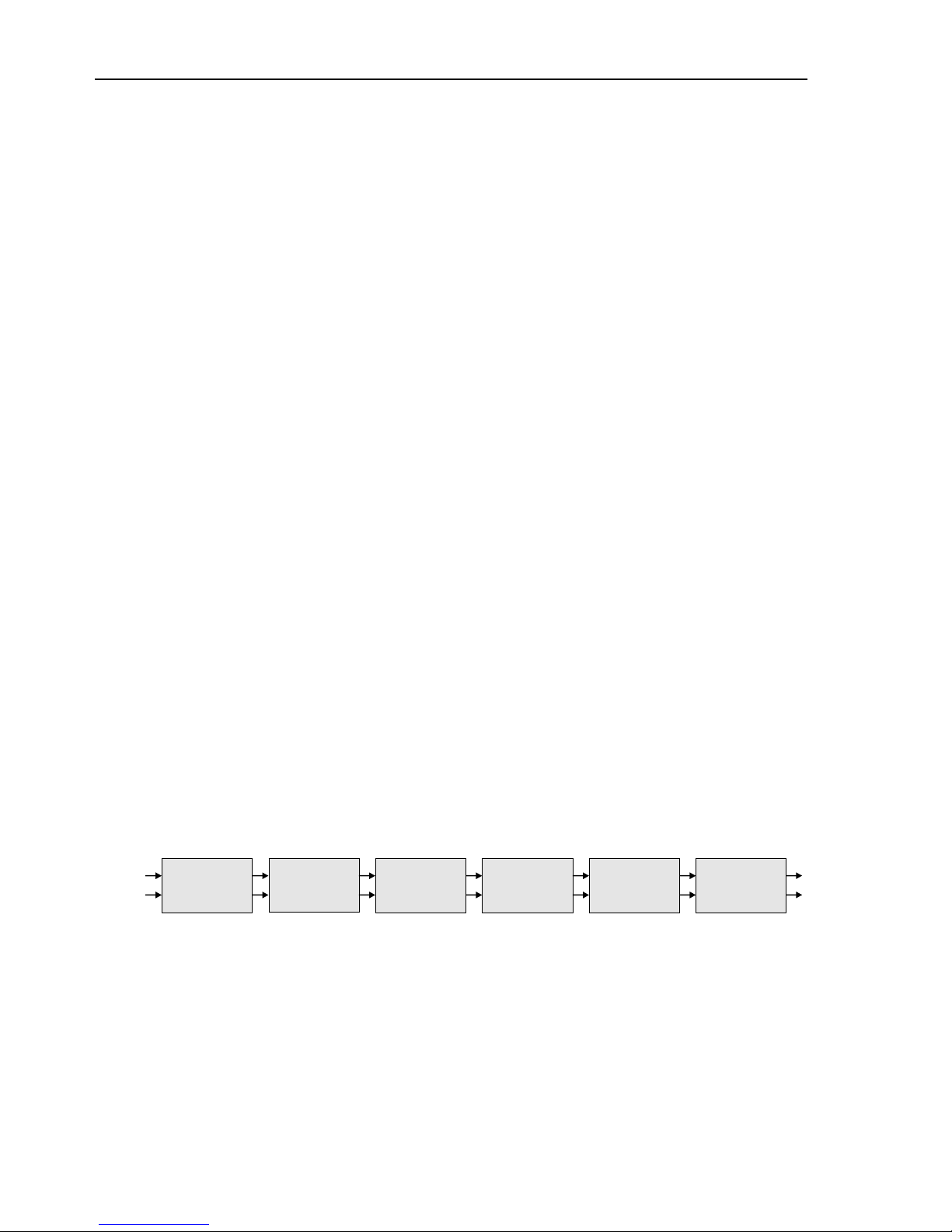
AGC
LEVELER
PHASE
ROTATORS
FOUR BAND
PROCESSOR
MULTIBAND
CLIPPERS
LOUDNESS
CLIPPERS
15kHz LP
PHASE COR.
S
implified Block Diagram
5

WARSANIS 1401FM USER MANUAL
SHORT DESCRIPTION OF THE 1401FM
The phase scrambler (rotator) makes peaks more symmetrical to fully benefit the
symmetrical peak overload characteristics of the FM medium. Voice and some music
can contain asymmetrical waveforms that can overload the processing circuit. By
removing asymmetrical waveforms from the audio, larger amounts of gain reduction
can be achieved with less distortion.
A 15kHz low pass filter prevents the AGC for >out of the band= frequencies.
The
AGC/Leveler acts more like a leveling device than as a compressor. The idea is
to keep consistent dynamic levels working into the four band audio processors. By
doing this, the limiter will operate within its >sweet spot= more often, and produce a
more consistent on air sound. The release and attack times are very slow. Hence,
the AGC/Leveler does not affect the dynamic range of the signal. When the signal is
under the gate threshold, the system slows down the release times to prevent noise
rush up. Program material below the gate threshold is considered as noise. The gate
threshold can be adjusted from -45 up to 0 dB via a trimmer inside the unit.
25, 50 or 75us pre-emphasis (specify when placing the order).
The four band processors have independent program-controlled time constants
according to the band frequency. In each band you can switch the density between
fast, medium and slow. The density control affects release times, attack times,
double sloop release times and more. You can also select the strereo tracking per
band. For example, you can link band three and four induvidually to provide the
stereo link. The Left and Right channel of Band one and two will work independently.
Multiband clipping is a soft clipping module that acts gently without adding audible
distortion to the signal. Filtering after the soft clippers prevents interharmonic
distortion.
Loudness clipping is a hard clipping module. This gives you excellent peak control.
Too much loudness clipping results in distortion. Although the loudness clipper
module is distortion controlled, it is possible that a certain amount of distortion is
hearable when to much clipping is used.
A sharp 15 kHz low pass filter prevents the stereo generator and transmitter from
out of the band frequencies.
Phase and overshoot filters are used to compensate overshoots and phase difference created by the crossover networks and low pass filters. Without the phase
correction filters you will not have a flat phase response. Without the overshoot filters
it is not unusual to get overshoots as high as 3 to 4 dB.
The safety clipper is only active to eliminate overshoots caused by very unusual
waveforms.
6

WARSANIS 1401FM USER MANUAL
The Stereo generator (option) uses a digitally controlled circuit to produce a high
quality composite signal. The Stereo generator has two outputs both with independent output amplifiers and level controls. A SCA (subcarrier) input is available for RDS
and a 19kHz (TTL) output for syncronisation. This stereo generator replaces all low
pass and high pass filters, overshoot filters, pre-emphasis and the stereo generator
of the transmitter or STL link.
Selectable de-emphasis on the analog output gives you the possibility to connect the
Warsanis 1401FM directly to a flat input of a external stereo generator if the
integrated stereo generator is not being used.
7
 Loading...