

Page 1

ELECTRIC WINCH
S8000 S9500
S12000 S14500
S9500SD
S9500HS
Assembly & Operating Instructions
Page 2

CONTENTS
INTRODUCTION ...................................................................................... 1
GETTING TO KNOW YOUR WINCH .......................................................1
WINCH ASSEMBLY AND MOUNTING ....................................................3
SAFETY PRECAUTIONS .........................................................................5
GENERAL TIPS FOR SAFE OPERATION ..............................................6
RIGGING TECHNIQUES ..........................................................................7
WINCHING TECHNIQUES A-Z .............................................................. 8
MAINTENANCE ...................................................................................... 9
REPLACING THE WIRE ROPE ............................................................. 10
TROUBLE SHOOTING .......................................................................... 10
WINCH ASSEMBLY DRAWING(S8000) .......................................... 1 1
WINCH PARTS LIST(S8000) ............................................................ 1 2
WINCH ASSEMBLY DRAWING(S9500) .......................................... 1 3
WINCH PARTS LIST(S9500) ............................................................ 1 4
WINCH ASSEMBLY DRAWING(S12000) ........................................ 1 5
WINCH PARTS LIST(S12000) .......................................................... 1 6
WINCH ASSEMBLY DRAWING(S14500) ........................................ 1 7
WINCH PARTS LIST(S14500) .......................................................... 1 8
WINCH ASSEMBLY DRAWING(S9500SD) ..................................... 19
WINCH PARTS LIST(S9500SD) ....................................................... 2 0
WINCH ASSEMBLY DRAWING(S9500HS) ..................................... 2 1
WINCH PARTS LIST(S9500HS) ....................................................... 2 2
SPECIFICATION(S8000) .................................................................. 23
SPECIFICATION(S9500) .................................................................. 2 4
SPECIFICATION(S12000) ................................................................ 2 5
SPECIFICATION(S14500) ................................................................ 2 6
SPECIFICATION(S9500SD) ............................................................. 2 7
SPECIFICATION(S9500HS) ............................................................. 28
WARRANTY ........................................................................................... 29
Page 3
1
INTRODUCTION
Congratulations on your purchase of a winch. We design and build winches to strict
specifications and with proper use and maintenance your winch should bring you
years of satisfying service.
WARNING - Read, understand and follow all instructions before
operating this device. Failure to read these instructions may result in
personal injury and/or damage to equipment or vehicles.
Your winch can develop tremendous pulling forces and if used unsafely or
improperly could result in property damage, serious injury or death. Throughout
this manual, you will find the following symbols for caution, warning and danger.
Pay particular attention to the notes preceded by these symbols as they are
written for your safety. Ultimately, safe operation of this device rests with you, the
operator.
Indicates a potentially hazardous situation which, if not avoided, may result in
minor or moderate injury. This notation is also used to alert against unsafe
practices.
Indicates a potentially hazardous situation which, if not avoided
could result in death or serious injury.
GETTING TO KNOW YOUR WINCH
Your winch is a powerful piece of machinery. It is important that you
understand the basics of its operation and specifications so that when you
need to use it, you can use it with confidence and safety. Below is a list of
the components of your winch and their uses. Practice using your winch
before you are in a situation to need to use it.
1. This winch is engineered for maximum line pull with only one layer of cable
spooled onto the winch drum (the first layer).
2. Motor: The motor is powered by a 12/24-volt battery and provides power to the
gear assembly which turns the drum and winds the wire rope in a direction.
CAUTION
WARNING
Page 4

2
3. Winch Drum: The winch drum is the cylinder on which the wire rope is stored. It
can be spooled In or Out by use of the remote lead switch.
4. Wire Rope: Your winch has a galvanized aircraft cable designed specifically for
load capacity of the rated line pull of this winch. The wire rope feeds on from
underneath the drum position through the supplied roller fairlead, it is looped at
the end to accept the clevis hook.
5. Roller Fairlead: When using the winch at an angle the roller fairlead acts to
guide the wire rope onto the drum and minimizes damage to the wire rope from
abrasion on the winch mount or drum flanges.
6. Gear Assembly System: The reduction gears convert the winch motor power
into extreme pulling forces.
7. External Braking System: Braking action is automatically applied to the winch
when the winch motor is stopped or there is a load on the wire rope. This is
achieved by a separate external mechanical brake which applies the braking
action. (Brakes are NOT designed as securing devices and the winch cables
should never be left attached when vehicle / equipment is in transport).
8. Free Spooling Clutch: The clutch allows the operator to manually disengage
(“CLUTCH OUT”) the spooling drum from the gear train. This called free spool.
Engaging the clutch (“CLUTCH IN”) locks the winch into the gear system.
9. Solenoid: Power from the vehicle battery flows through the weatherproof switch
before being directed to the winch motor.
10. Wired Remote lead Switch: The remote switch leads have a dual switch for
powering in or powering out your winch drum. The remote control allows you to
stand clear of the wire rope when the winch is under load.
11. Wireless remote: This is designed and offered for ‘Offroad’ or ‘None
Commercial’ use only and is not included in any warranty offered, This allows
the operator to always control the winch from up to 50 Ft away.
12. Universal Flat Bed Mounting Channel: (Optional) Your winch could have been
optionally supplied with a flat bed mounting channel that can be mounted to
most flat surfaces such as trailers, truck beds and structures etc. The mounting
channel also has a number of mounting holes and holes to accept your roller
fairlead.
Page 5
3
13. Pulley/Snatch Block: (Optional) If your winch is supplied with a snatch block
which can double the pulling power of the winch, or change the pulling direction
without damaging the wire rope. We recommend you to use a double line and
snatch block for pulling over 70% of the rated line pull.
WINCH ASSEMBLY AND MOUNTING
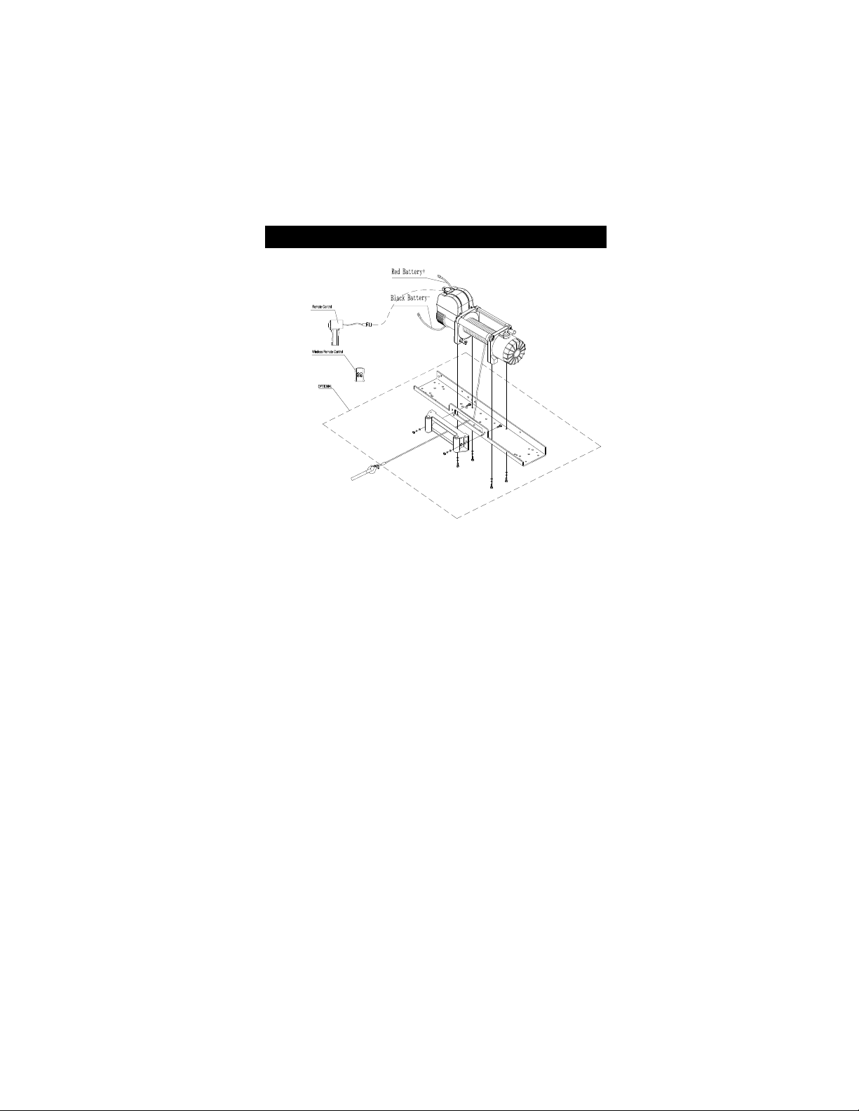
1. Your winch is designed with a bolt pattern that is standard in this class of
winch. Many winch mounting kits are available that utilize this bolt pattern for
the most popular vehicle and mounting channels. If you cannot find a kit
locally, contact us and we will provide you with the name of a dealer near you.
If you utilize the mounting channel you must ensure that it is mounted on a flat
surface so that the three major sections (motor, drum and gear housing) are
properly aligned. Proper alignment of the winch will allow even distribution of
the full rated load and reduce the chance of damaging winch or equipment.
2. Start by connecting the Roller Fairlead to the Mounting Channel using 2 each
of the Cap Bolt M10 X 35, Flat Washer, Lock Washer and securing with M10
Nut (Make sure the bolt is placed through the mounting channel and roller
fairlead from inside the channel. This will allow enough clearance for the winch
to be placed in the channel without obstruction.)
3. Assemble the winch to the Mounting Channel by first pulling and releasing the
clutch knob to “Off” position (Free Spooling). Pull out a few inches of cable
from the drum and feed the wire loop through the opening in the front of the
mounting channel and roller fairlead. Now, using the remaining M10 x 35 Cap
Page 6
4
Bolts, Flat Washer, Lock Washer and M10 Nut secure the winch to the
mounting channel.
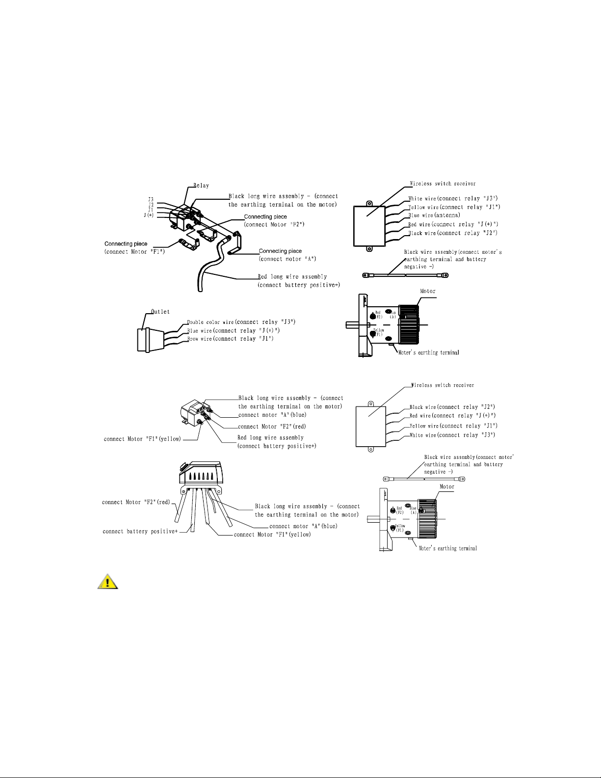
4. Connect the battery and motor leads as the drawing above. Remember every
type of winch is different.
5. Connect the winch motor leads as detailed below:
CAUTION – Batteries contain gases which are flammable and explosive.
Wear eye protection during installation and remove all jewelry. Do not lean over
battery while making connections.
6. Assemble the Clevis Hook to the cable. Take off the pin from the Clevis Hook,
connect the Clevis Hook to the cable and mount the pin back to the Clevis
Hook.
Page 7
5
7. Always use the Hand Saver (Optional) when free-spooling and re-spooling the
wire rope. Using the Hand Saver keeps your hands and fingers away from the
rotating drum.
8. Check for proper drum rotation. Pull or turn the clutch knob to the “OUT”
“Disengage” position (Free-spooling). Pull out some cable from the drum, and
then turn the clutch knob to the “IN” “Engage” position to engage the gears.
Press the cable out button on the remote lead switch. If the drum is turning and
releasing cable, then your connections are accurate. If the drum is turning and
collecting more cable, then reverse the leads on the motor. Repeat and check
rotation.
SAFETY PRECAUTIONS
WARNING
WARNING – DO NOT EXCEED RATED CAPACITY.
WARNING – Intermittent use only.
WARNING – DO NOT use winch for lifting or moving people or animals
WARNING - A minimum of five wraps of cable around the drum barrel is
necessary for pulling and holding the rated load. The cable clamp is not
designed to hold the load without the 5 wraps of cable around the drum.
WARNING - Keep yourself and others a safe distance to the side of the
cable when under tension.
WARNING – The wire rope may break before the motor stalls. For heavy
loads at or near rated capacity, use a pulley block/snatch block to reduce
the load on the wire rope.
WARNING -Never stand or step over a cable, or near a cable under load
using a winch blanket or sail is recommended.
WARNING - Don’t move the vehicle to pull a load (towing) on the winch
cable. This could result in cable breakage.
WARNING-Disconnect the remote control and battery leads when not in
use.
WARNING- Do not exceed maximum pull rating. Avoid “shock loading”
by using the remote lead switch intermittently to take up the slack in the
Page 8
6
wire rope. “Shock loading” can far exceed the rated capacity for the wire
rope and drum and will result in damaging winch and brake.
WARNING- DONOT use you winch as securing device it is not designed
for this and will result in damaging winch and brake.
WARNING- Do not exceeds maximum line pull ratings shown on the
tables.
WARNING-When re-spooling the cable, ensure that the cable spools in
the under-wind position with the cable entering the drum from the
bottom, not the top. To re-spool correctly, and while wearing gloves,
keep a slight load on the cable while pushing the remote control button to
draw in the cable. Walk toward the winch NOT allowing the winch cable
to slide through your hands. DO NOT let your hands get within 12″(30cm)
of the winch while re-spooling. Turn off the winch and repeat the
procedure until a few feet of cable is left. Disconnect the remote control
and finish spooling by hand by rotating the drum manually with the clutch
disengaged. Keep hands clear of the fairlead and drum while the winch is
under power.
Do not use as a hoist. Do not use for overhead lifting.
Failure to heed these warnings may result in personal injury and/or
property damage.
WARNING - Use gloves to protect hands when handling the cable. Never
let the cable slide through your hands.
WARNING – Never connect the cable back to itself.
Apply blocks to the wheels of the vehicle when on an incline.
No modifications, alterations, or deviation to the winch are authorized by the
manufacturer and MUST not be made.
Duration of winching pulls should be kept as short as possible. If the motor
becomes uncomfortably hot to the touch, stop winching immediately and let
it cool down for a few minutes. Do not winch for more than two minutes at
or near the maximum rated load without resting for 8 minutes.
Page 9
7
CAUTION - If the motor stalls DO NOT maintain winching. Electric
winches are designed and made for intermittent use and should be used in
conjunction with their duty cycles.
CAUTION - Never release the free-spool clutch when there is a load on
the winch as the load will roll backwards.
CAUTION - Use hand saver hook when handling the hook for spooling or
un-spooling the wire rope.
GENERAL TIPS FOR SAFE OPERATION
• The winch and its all-derivative types are rated at rated capacity
when spooling the first rope layer on the drum. Overloading can
damage the winch / motor / or wire rope. For loads over 70% of
rated line pull, we recommend the use of the pulley block / snatch
block to double the wire rope line and reduce the strain. This will
aid in two ways: It will reduce the number of rope layers on the drum
and reduce the load on the wire rope by as much as 50%. When
doubling the line back to the vehicle, attach to the frame or other
load bearing part.
• The vehicle engine should be kept running during operation of the
winch to minimize battery drain and maximize power and speed of
the winch. If the winch is used for a considerable time with the
engine switched off the battery may be drained and too weak to
restart the engine
• Get to know your winch before you need to use it. We recommend
that you set up a few test runs to familiarize yourself with rigging
techniques; the sounds your winch makes under various loads and
the way the cable spools on the drum, etc.
• Inspect the wire rope and equipment before each use. A frayed or
damaged rope must be replaced immediately. Use only
manufacturer’s identical replacement rope with the exact
specifications. (Ropes are not covered by any warranty offered)
• Inspect the winch installation and bolts to ensure that all bolts are
tight before each operation.
• Never connect the winch cable back to itself. This will cause cable
to damage. Always use a snatch block, sling or chain of suitable
strength as shown in the illustrations.
• Store the remote control lead inside your vehicle in a safe place.
• Any winch that appears to be damaged in any way, is found to be
worn, or operates abnormally MUST BE REMOVED FROM
Page 10
8
SERVICE UNTIL REPAIRED OR REPLACED. It is recommended
that the necessary repairs be made by a manufacturer’s authorized
repair facility ONLY.
• Pull only on areas of the vehicle as specified by the vehicle
manufacturer.
• Only accessories, attachments and/or adapters supplied by the
manufacturer shall be used.
RIGGING TECHNIQUES
Self Recovery
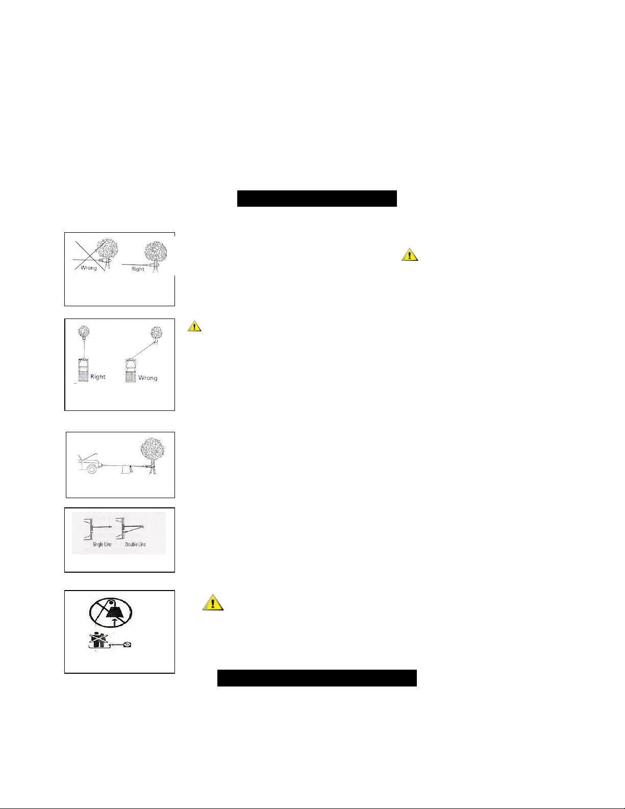
Locate a suitable anchor such as a strong tree trunk or boulder.
Always use a sling as an anchor point. CAUTION Do not attach
the clevis hook back onto the cable as this could cause damage to
the cable.
As shown in Fig 3.1
Do not winch from an acute angle as the wire rope will pile up
on one side of the drum causing damage to wire rope and the
winch. Fig 3.2
Short pulls from an angle can be used to straighten the vehicle.
Long pulls should be done with the wire rope at a 90° angle to the
winch/vehicle.
When pulling a heavy load, place a blanket or jacket over the wire
rope five or six feet from the hook because in the event of a broken
cable it will dampen the snap back. For additional protection open
the hood/bonnet of the vehicle as shown in Fig 3.3
For pulls over 6800lbs, we recommend the use of the snatch
block/pulley block to double line the wire rope. Fig 3.4
This reduces the load on the winch and the strain on the rope by
approximately 50%.
WARNING - Never use your winch for overhead hoisting or
for lifting people or moving people.
WINCHING TECHNIQUES A-Z
a. Take time to asses your situation and plan your pull.
b. Put on gloves to protect your hands.
Fig 3.1
Fig 3.2
Fig 3.3
Fig 3.4
Fig 3.5
Page 11

9
c. Disengage the clutch where possible to allow free-spooling and also save battery
power.
d. Attach the hand saver hook to the clevis hook.
e. Pull out the wire rope to your desired anchor point safely.
f. Secure the clevis hook to the anchor point: Sling, chain or snatch block. Do not
attach the hook back onto the wire rope.
g. Engage the clutch.
h. Connect the remote control lead to the winch.
i. Start your engine to ensure power is being replenished to the vehicle battery.
j. Power in the wire rope guiding the wire under tension to draw up the slack in the
wire. Once the wire is under tension stand well clear. Never stand or step over the
wire rope under tension.
k. Double check your anchors and make sure all connections are secure.
l. Inspect the wire rope. Make sure there are at least 5 wraps of wire rope around the
winch drum.
m. Drape a blanket or sail (Sold separately) over the wire rope approximately 5 to 6
feet from the hook. Open the hood/bonnet for added protection.
n. Clear the area. Make sure all people, spectators are well back and that no one is
directly in front or behind the vehicle or anchor point.
o. Begin winching. Be sure that the wire rope is winding evenly and tightly around the
drum. The vehicle that is being winched can be slowly driven to add assistance to the
winching process. Avoid shock loading; keep the wire rope under tension.
p. The vehicle to be winched should be placed in neutral and the emergency brake
released. Only release the brake pedal when under full tension. Avoid shock loading
to the winch. This can damage the winch, rope and vehicle.
q. The winch is meant for intermittent use. Under full load with a single line rig do not
power in for more than 2 minutes without letting the motor cool down for a few minutes
and then resume the winching operation.
r. The winching operation is complete once the vehicle is on stable ground and or can
drive under its own power.
s. Secure the vehicle. Be sure to set the brakes and place the vehicle in park.
Page 12

10
t. Release the tension on the wire rope. The winch is NOT designed as securing
device and should NEVER hold a load whilst in transport, winch cable MUST be
released when equipment or vehicle is secure.
u. Disconnect the wire rope from the anchor and NEVER leave connected.
v. Rewind the wire rope. Make sure that any wire already on the drum has spooled
tightly and neatly. If not, draw out the wire and re-spool from the point where the rope
is tight.
w. Keep your hands clear of the winch drum and fairlead as the wire rope is being
drawn in.
x. Secure the hook and hook strap.
y. Disconnect the remote control lead and store in a clean, dry place.
z. Clean and inspect connections and mounting hardware for next winching operation.
MAINTENANCE
1. Periodically check the tightness of mounting bolts and electrical connections.
Remove all dirt or corrosion and always keep clean.
2. Do not attempt to disassemble the gear box. Repairs should be done by the
manufacturer or an authorized repair center.
3. The gear box has been lubricated using a high temperature lithium grease and is
sealed at the factory. No internal lubrication is required.
REPLACING THE WIRE ROPE
1. If the wire rope has become worn or is beginning to show signs of fraying, it must
be replaced before being used again. To do this, remove the defective rope by
free spooling. Remove the bolt M8x10 on the drum and release the rope.
2. Insert the end of the new rope and secure the M8 x 10 mm bolt tightly.
3. Engage the clutch and re-spool the new rope on the drum keeping tension on the
rope as it spools. Ensure that the rope is re-spooling in the under-wind position.
WARNING - Only replace the wire rope with the identical replacement part
recommended by the manufacturer. Steel or synthetic ropes are NOT
covered by any warranty offer and are sole responsibility of the owner or
user to maintain and replace if necessary.
Page 13
11
TROUBLE SHOOTING
SYMPTOM
POSSIBLE CAUSE
SUGGESTED ACTION
Motor does not
turn on
-Remote Assembly not
connected properly
-Check remote lead and connections.
-Loose battery cable
connections
-Check battery and connections.
-Defective remote
assembly
-Replace remote lead assembly.
-Defective motor
-Check for voltage at armature port with Switch
pressed. If no voltage is present, replace motor.
-Water has entered
motor
-Allow to drain and dry. Run winch until
completely dry.
Motor runs but
drum does not
turn
-Clutch not engaged
-Turn clutch to the “In” position. If problem
persists, ask a technician to check and repair.
Motor runs
slowly or
without normal
power
-Insufficient current or
voltage
-Operate winch while vehicle motor running.
Motor
overheating
-Winch running for too
long
-Allow winch to cool down periodically.
Motor runs in
one direction
only
-Loose or corroded
battery cable or motor
cable connections.
-Clean and tighten.
-Repair or replace switch assembly.
Page 14
12
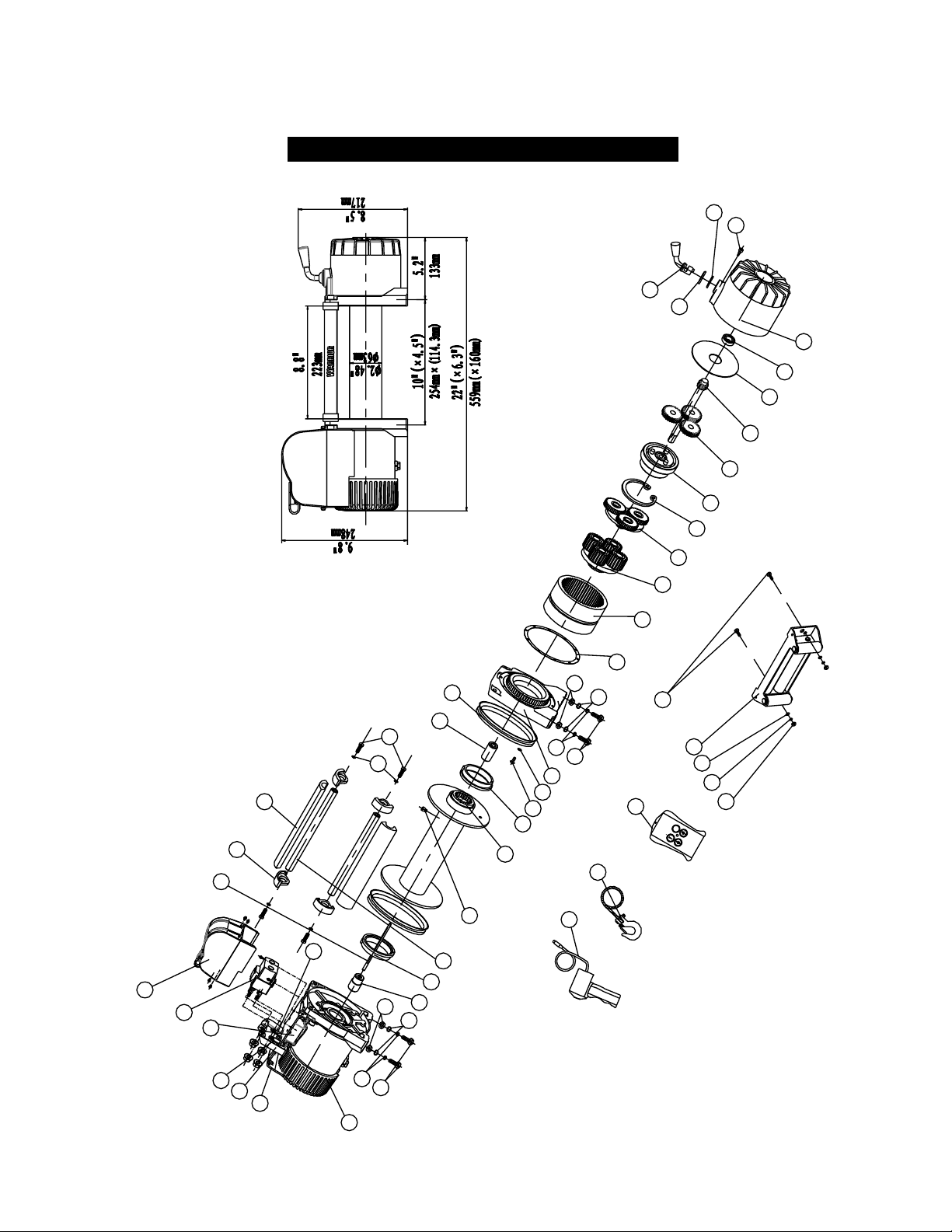
WINCH ASSEMBLY DRAWING(S8000)
14
4
5
2
3
7
15
1
5
4
3
2
43
7
9
12
16
17
20
6
19
18
22
23
25
26
27
24
13
8
11
10
37
36
35
34
32
38
33
39
40
41
30
31
2
4
3
5
28
29
42
21
45
46
44
Page 15
13
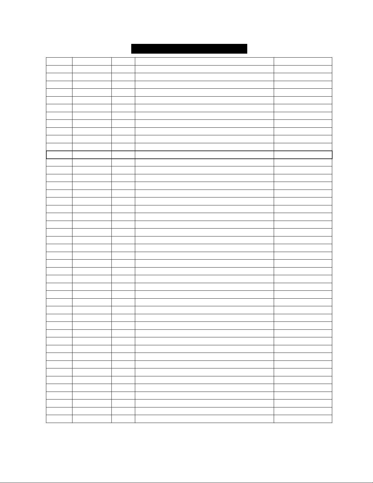
WINCH PARTS LIST (S8000)
No.
Part #
Qty
Description
Remark
1
V950100
1
Motor Assembly
2
V800001
6
Cap Screw M10 x 35
3
V800002
6
Lock Washer Φ10
4
V800003
6
Think Flat Washer Φ10
5
V800004
6
Hex Flange Nut M10
6
V950200
1
Break / Shaft Assembly
7
V1200005
2
Bushing—Drum
8
V800006
2
Tie Bar
9
V800007
1
Screw M8 x 10
10
V800008
4
Think Flat Washer Φ8
11
V800009
4
Cap Screw M8 x 30
12
V1200300
1
Drum Assembly
13
V800010
8
Screw M5 x18
14
V800011
8
Lock Washer Φ5
15
V1200012
1
End Bearing
16
V800013
1
Gasket
17
V800014
1
Gear—Ring
18
V800400
1
Gear Carrier Assembly(Output)
19
V800500
1
Gear Carrier Assembly(Intermediate)
20
V800600
1
Gear Carrier Assembly(Intput)
21
V800015
1
Gear—Input Sun
22
V800016
1
Trust Washer
23
V800017
1
Gear—Housing
24
V800018
1
Clutch Screw
25
V800019
1
Ring Seals
26
V800020
1
Clutch Cover
27
V1200021
1
Clutch
28
V800RS
1
Remote Control Switch(R8)
29
V800800
1
Cable Assembly
30
V80WRS
1
Wireless Remote Control Switch
31
V800900
1
Roller Fairlead
32
V800022
1
Mounting Play
800VS12/800VA12
33
V800023
1
Connecting Piece
800VS12/800VA12
34
V800024
1
Connecting Piece
800VS12/800VA12
35
V801300
1
Wireless Switch Receiver
800VS12/800VA12
36
V1201400
1
Relay with Screw Assembly
800VS12/800VA12
37
V951500
1
Cover with Screw Assembly
800VS12/800VA12
38
V800025
1
Connecting Piece
800VS12/800VA12
39
V1200026
4
Connecting Block
40
V1200027
2
Connecting Rod Sets
41
V800028
2
Ring Seals
42
V800029
1
Six angle bar
43
V800030
1
Coupling
44
V800031
1
Coupling
45
V800032
1
Circlip For Hole
46
V800033
1
Bearing
Page 16
14
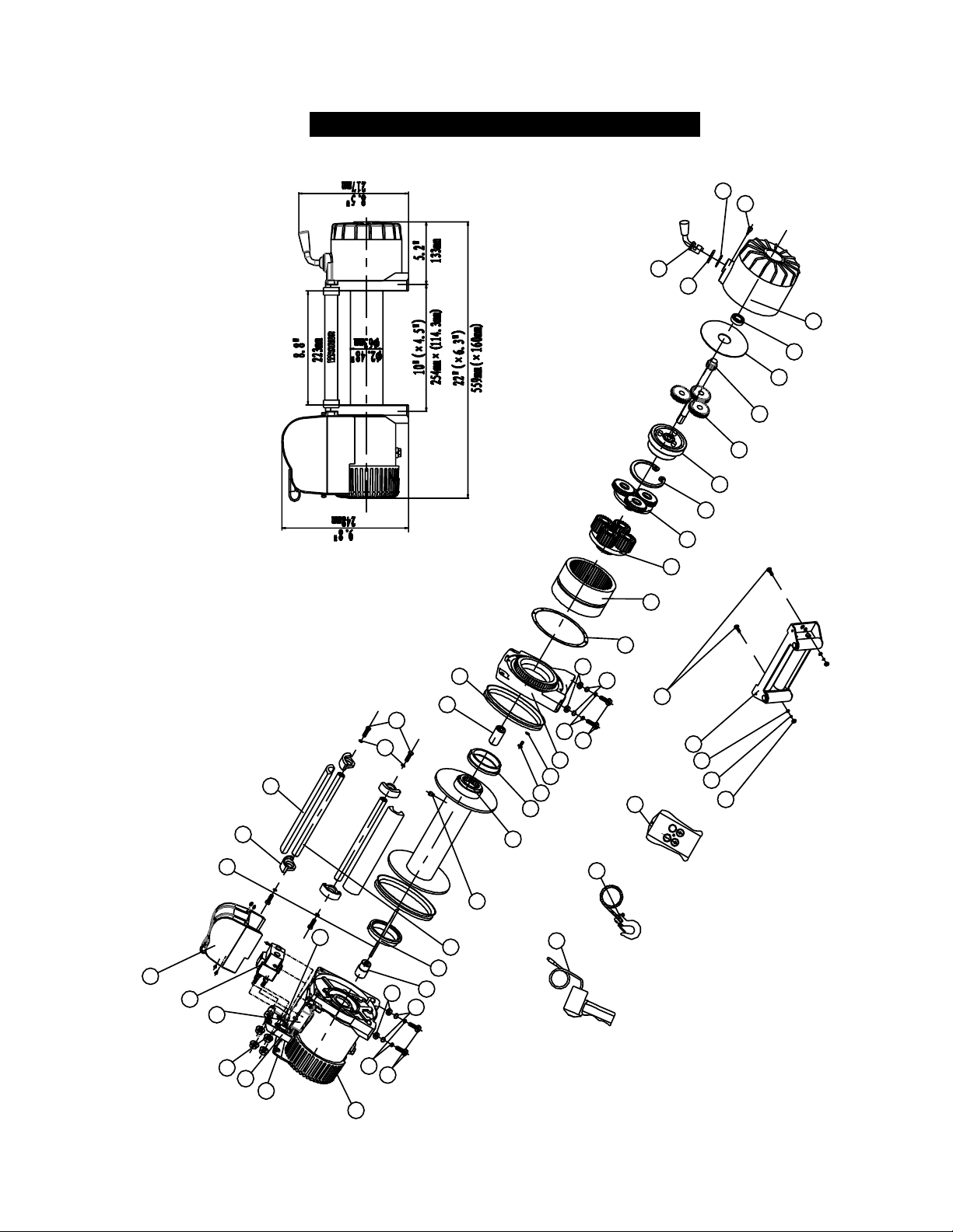
WINCH ASSEMBLY DRAWING(S9500)
14
4
5
2
3
7
15
1
5
4
3
2
7
9
12
16
17
19
18
13
8
11
10
37
36
35
34
32
38
33
39
40
41
30
31
2
4
3
5
28
29
42
43
44
20
6
22
23
25
26
27
24
21
45
46
Page 17
15
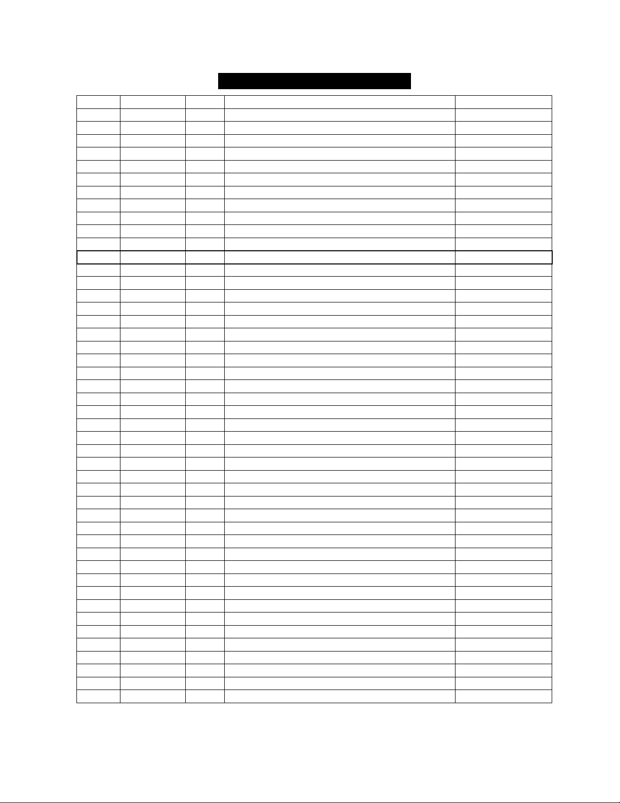
WINCH PARTS LIST (S9500)
No.
Part #
Qty
Description
Remark
1
V950100
1
Motor Assembly
2
V950001
6
Cap Screw M10 x 35
3
V950002
6
Lock Washer Φ10
4
V950003
6
Think Flat Washer Φ10
5
V950004
6
Hex Flange Nut M10
6
V950200
1
Break / Shaft Assembly
7
V1200005
2
Bushing—Drum
8
V950006
2
Tie Bar
9
V950007
1
Screw M8 x 10
10
V950008
4
Think Flat Washer Φ8
11
V950009
4
Cap Screw M8 x 30
12
V1200300
1
Drum Assembly
13
V950010
8
Screw M5 x18
14
V950011
8
Lock Washer Φ5
15
V1200012
1
End Bearing
16
V950013
1
Gasket
17
V950014
1
Gear—Ring
18
V950400
1
Gear Carrier Assembly(Output)
19
V950500
1
Gear Carrier Assembly(Intermediate)
20
V950600
1
Gear Carrier Assembly(Input)
21
V950015
1
Gear—Input Sun
22
V950016
1
Trust Washer
23
V950017
1
Gear—Housing
24
V950018
1
Clutch Screw
25
V950019
1
Ring Seals
26
V950020
1
Clutch Cover
27
V1200021
1
Clutch
28
V950RS
1
Remote Control Switch(R8)
29
V950800
1
Cable Assembly
30
V95WRS
1
Wireless Remote Control Switch
31
V950900
1
Roller Fairlead
32
V950022
1
Mounting Play
950VS12/950VA12
33
V950023
1
Connecting Piece
950VS12/950VA12
34
V950024
1
Connecting Piece
950VS12/950VA12
35
V951300
1
Wireless Switch Receiver
950VS12/950VA12
36
V1201400
1
Relay with Screw Assembly
950VS12/950VA12
37
V951500
1
Cover with Screw Assembly
950VS12/950VA12
38
V950025
1
Connecting Piece
950VS12/950VA12
39
V1200026
4
Connecting Block
40
V1200027
2
Connecting Rod Sets
41
V950028
2
Ring Seals
42
V950029
1
Six angle bar
43
V950030
1
Coupling
44
V950031
1
Coupling
45
V950032
1
Circlip For Hole
46
V950033
1
Bearing
Page 18
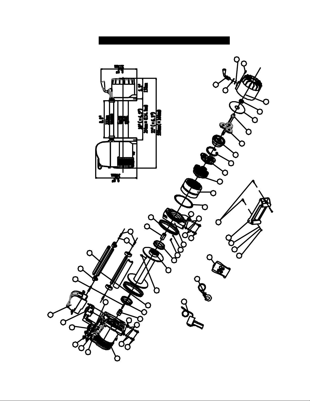
16
WINCH ASSEMBLY DRAWING(S12000)
14
4
5
2
3
7
15
1
5
4
3
2
7
9
12
16
17
19
18
13
8
11
10
37
36
35
34
32
38
33
39
40
41
30
31
2
4
3
5
28
29
42
43
44
20
6
22
23
25
26
27
24
21
45
46
Page 19
17
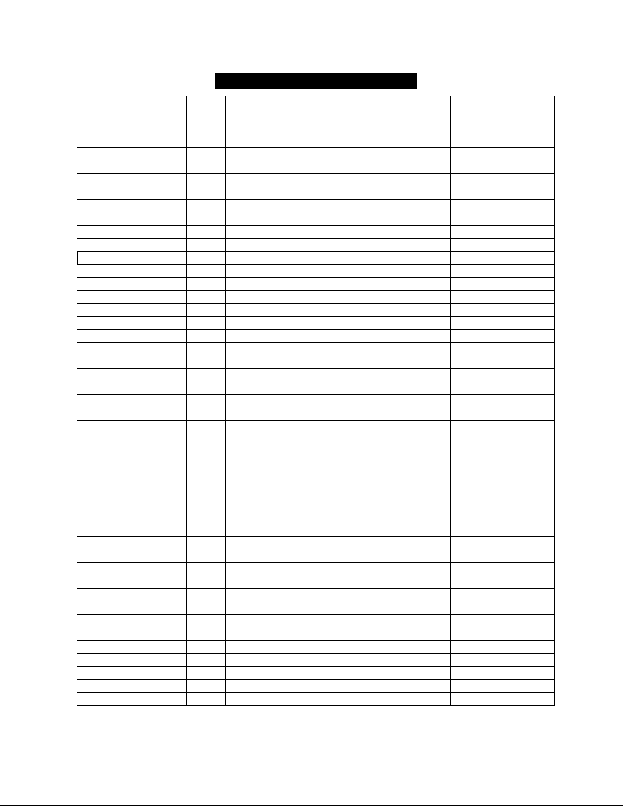
WINCH PARTS LIST (S12000)
No.
Part #
Qty
Description
Remark
1
V1200100
1
Motor Assembly
2
V1200001
6
Cap Screw M10 x 35
3
V1200002
6
Lock Washer Φ10
4
V1200003
6
Think Flat Washer Φ10
5
V1200004
6
Hex Flange Nut M10
6
V1200200
1
Break / Shaft Assembly
7
V1200005
2
Bushing—Drum
8
V1200006
2
Tie Bar
9
V1200007
1
Screw M8 x 10
10
V1200008
4
Think Flat Washer Φ8
11
V1200009
4
Cap Screw M8 x 30
12
V1200300
1
Drum Assembly
13
V1200010
8
Screw M5 x18
14
V1200011
8
Lock Washer Φ5
15
V1200012
1
End Bearing
16
V1200013
1
Gasket
17
V1200014
1
Gear—Ring
18
V1200400
1
Gear Carrier Assembly(Output)
19
V1200500
1
Gear Carrier Assembly(Intermediate)
20
V1200600
1
Gear Carrier Assembly(Intput)
21
V1200015
1
Gear—Input Sun
22
V1200016
1
Trust Washer
23
V1200017
1
Gear—Housing
24
V1200018
1
Clutch Screw
25
V1200019
1
Ring Seals
26
V1200020
1
Clutch Cover
27
V1200021
1
Clutch
28
V120RS
1
Remote Control Switch(R8)
29
V1200800
1
Cable Assembly
30
V120WRS
1
Wireless Remote Control Switch
31
V1200900
1
Roller Fairlead
32
V1200022
1
Mounting Play
120VS12/120VA12
33
V1200023
1
Connecting Piece
120VS12/120VA12
34
V1200024
1
Connecting Piece
120VS12/120VA12
35
V1201300
1
Wireless Switch Receiver
120VS12/120VA12
36
V1201400
1
Relay with Screw Assembly
120VS12/120VA12
37
V1201500
1
Cover with Screw Assembly
120VS12/120VA12
38
V1200025
1
Connecting Piece
120VS12/120VA12
39
V1200026
4
Connecting Block
40
V1200027
2
Connecting Rod Sets
41
V1200028
2
Ring Seals
42
V1200029
1
Six angle bar
43
V1200030
1
Coupling
44
V1200031
1
Coupling
45
V1200032
1
Circlip For Hole
46
V1200033
1
Bearing
Page 20
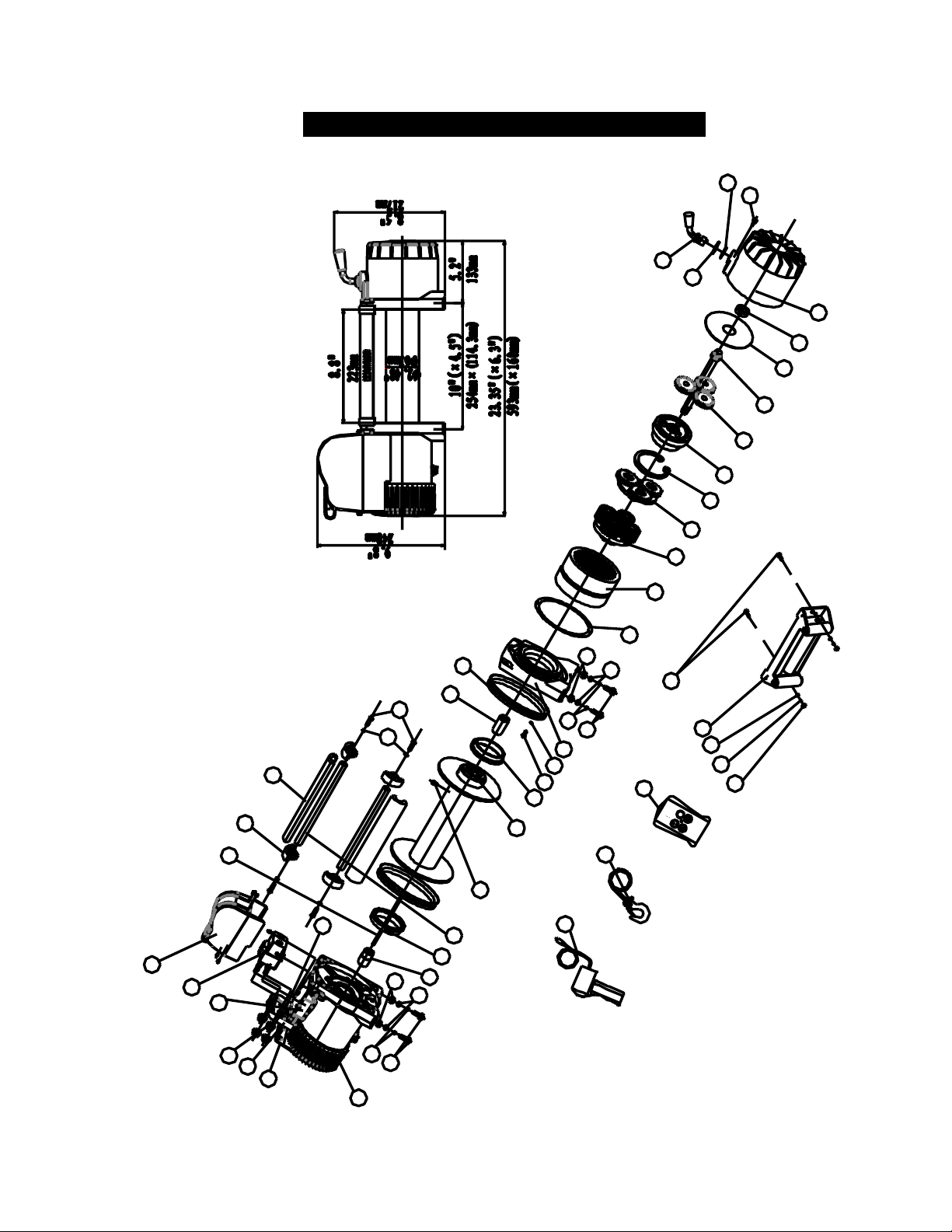
18
WINCH ASSEMBLY DRAWING(S14500)
14
4
5
2
3
7
15
1
5
4
3
2
7
9
12
16
17
19
18
13
8
11
10
37
36
35
34
32
38
33
39
40
41
30
31
2
4
3
5
28
29
42
43
44
20
6
22
23
25
26
27
24
21
45
46
Page 21
19
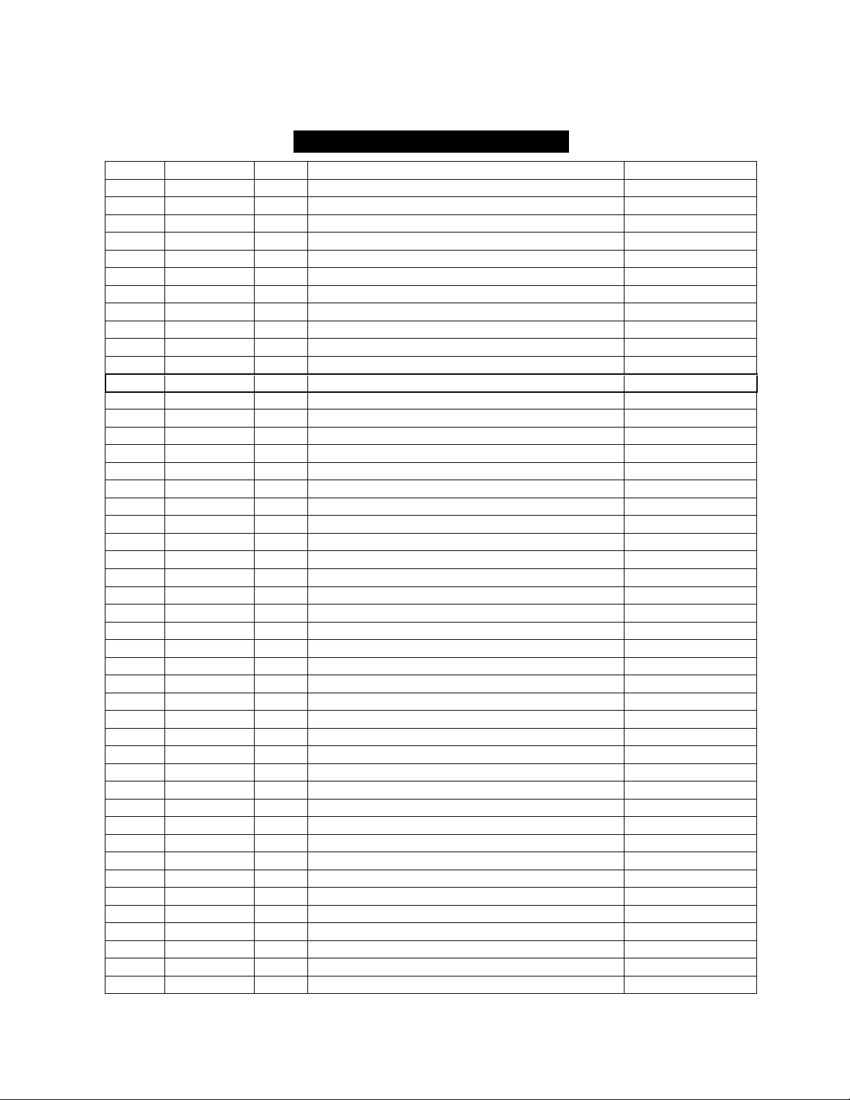
WINCH PARTS LIST (S14500)
No.
Part #
Qty
Description
Remark
1
V1450100
1
Motor Assembly
2
V1450001
6
Cap Screw M10 x 35
3
V1450002
6
Lock Washer Φ10
4
V1450003
6
Think Flat Washer Φ10
5
V1450004
6
Hex Flange Nut M10
6
V1450200
1
Break / Shaft Assembly
7
V1450005
2
Bushing—Drum
8
V1450006
2
Tie Bar
9
V1450007
1
Screw M8 x 10
10
V1450008
4
Think Flat Washer Φ8
11
V1450009
4
Cap Screw M8 x 30
12
V1450300
1
Drum Assembly
13
V1450010
8
Screw M5 x18
14
V1450011
8
Lock Washer Φ5
15
V1450012
1
End Bearing
16
V1450013
1
Gasket
17
V1450014
1
Gear—Ring
18
V1450400
1
Gear Carrier Assembly(Output)
19
V1450500
1
Gear Carrier Assembly(Intermediate)
20
V1450600
1
Gear Carrier Assembly(Input)
21
V1450015
1
Gear—Input Sun
22
V1450016
1
Trust Washer
23
V1450017
1
Gear—Housing
24
V1450018
1
Clutch Screw
25
V1450019
1
Ring Seals
26
V1450020
1
Clutch Cover
27
V1450021
1
Clutch
28
V145RS
1
Remote Control Switch(R8)
29
V1450800
1
Cable Assembly
30
V145WRS
1
Wireless Remote Control Switch
31
V1450900
1
Roller Fairlead
32
V1450022
1
Mounting Play
145VS12/145VA12
33
V1450023
1
Connecting Piece
145VS12/145VA12
34
V1450024
1
Connecting Piece
145VS12/145VA12
35
V1451300
1
Wireless Switch Receiver
145VS12/145VA12
36
V1451400
1
Relay with Screw Assembly
145VS12/145VA12
37
V1451500
1
Cover with Screw Assembly
145VS12/145VA12
38
V1450025
1
Connecting Piece
145VS12/145VA12
39
V1450026
4
Connecting Block
40
V1450027
2
Connecting Rod Sets
41
V1450028
2
Ring Seals
42
V1450029
1
Six angle bar
43
V1450030
1
Coupling
44
V1450031
1
Coupling
45
V1450032
1
Circlip For Hole
46
V1450033
1
Bearing
Page 22
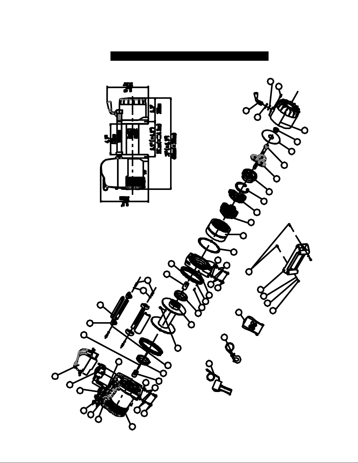
20
WINCH ASSEMBLY DRAWING(S9500SD)
14
4
52
3
7
15
1
5
4
3
2
7
9
12
16
17
19
18
13
8
11
10
37
36
35
34
32
38
33
39
40
41
30
31
2
4
3
5
28
29
42
43
44
20
6
22
23
25
26
27
24
21
45
46
Page 23
21
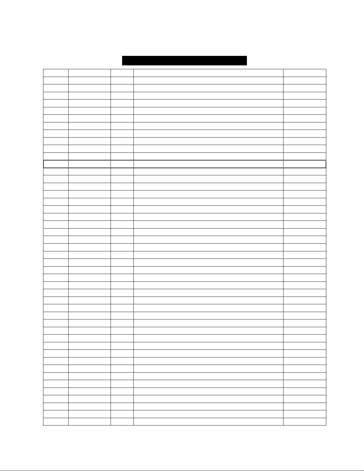
WINCH PARTS LIST (S9500SD)
No.
Part #
Qty
Description
Remark
1
V950100
1
Motor Assembly
2
V95SD0001
6
Cap Screw M10 x 35
3
V95SD0002
6
Lock Washer Φ10
4
V95SD0003
6
Think Flat Washer Φ10
5
V95SD0004
6
Hex Flange Nut M10
6
V950200
1
Break / Shaft Assembly
7
V1200005
2
Bushing—Drum
8
V95SD0006
2
Tie Bar
9
V95SD0007
1
Screw M8 x 10
10
V95SD0008
4
Think Flat Washer Φ8
11
V95SD0009
4
Cap Screw M8 x 30
12
V95SD0300
1
Drum Assembly
13
V95SD0010
8
Screw M5 x18
14
V95SD0011
8
Lock Washer Φ5
15
V1200012
1
End Bearing
16
V95SD0013
1
Gasket
17
V95SD0014
1
Gear—Ring
18
V95SD0400
1
Gear Carrier Assembly(Output)
19
V95SD0500
1
Gear Carrier Assembly(Intermediate)
20
V95SD0600
1
Gear Carrier Assembly(Input)
21
V95SD0015
1
Gear—Input Sun
22
V95SD0016
1
Trust Washer
23
V95SD0017
1
Gear—Housing
24
V95SD0018
1
Clutch Screw
25
V95SD0019
1
Ring Seals
26
V95SD0020
1
Clutch Cover
27
V1200021
1
Clutch
28
V95SDRS
1
Remote Control Switch(R8)
29
V95SD0800
1
Cable Assembly
30
V95SDWRS
1
Wireless Remote Control Switch
31
V95SD0900
1
Roller Fairlead
32
V95SD0022
1
Mounting Play
33
V95SD0023
1
Connecting Piece
34
V95SD0024
1
Connecting Piece
35
V95SD1300
1
Wireless Switch Receiver
36
V1201400
1
Relay with Screw Assembly
37
V951500
1
Cover with Screw Assembly
38
V95SD0025
1
Connecting Piece
39
V1200026
4
Connecting Block
40
V95SD0027
2
Connecting Rod Sets
41
V95SD0028
2
Ring Seals
42
V95SD0029
1
Six angle bar
43
V95SD0030
1
Coupling
44
V95SD0031
1
Coupling
45
V95SD0032
1
Circlip For Hole
46
V95SD0033
1
Bearing
Page 24
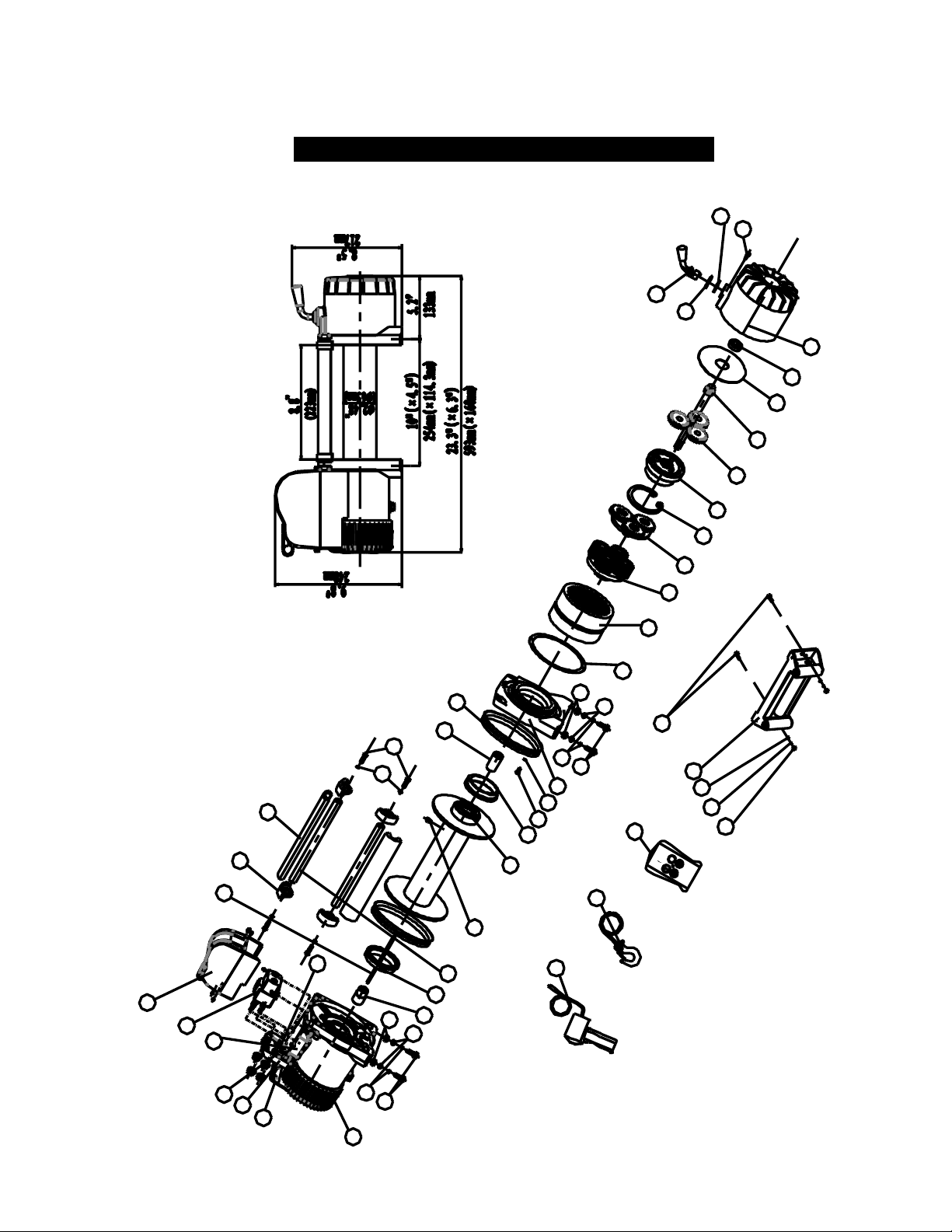
22
WINCH ASSEMBLY DRAWING(S9500HS)
14
4
5
2
3
7
15
1
5
4
3
2
7
9
12
16
17
19
18
13
8
11
10
37
36
35
34
32
38
33
39
40
41
30
31
2
4
3
5
28
29
42
43
44
20
6
22
23
25
26
27
24
21
45
46
Page 25
23
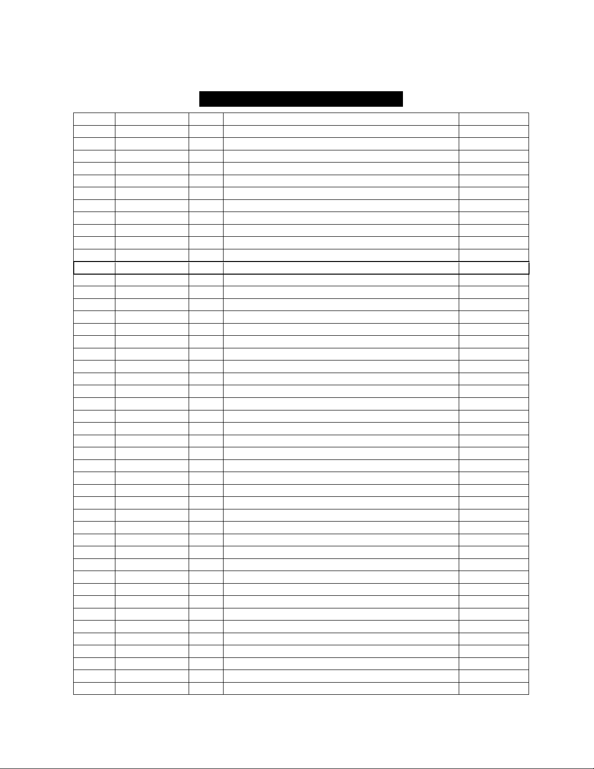
WINCH PARTS LIST (S9500HS)
No.
Part #
Qty
Description
Remark
1
V1200100
1
Motor Assembly
2
V95HS0001
6
Cap Screw M10 x 35
3
V95HS0002
6
Lock Washer Φ10
4
V95HS0003
6
Think Flat Washer Φ10
5
V95HS0004
6
Hex Flange Nut M10
6
V95HS0200
1
Break / Shaft Assembly
7
V1200005
2
Bushing—Drum
8
V95HS0006
2
Tie Bar
9
V95HS0007
1
Screw M8 x 10
10
V95HS0008
4
Think Flat Washer Φ8
11
V95HS0009
4
Cap Screw M8 x 30
12
V1200300
1
Drum Assembly
13
V95HS0010
8
Screw M5 x18
14
V95HS0011
8
Lock Washer Φ5
15
V1200012
1
End Bearing
16
V95HS0013
1
Gasket
17
V95HS0014
1
Gear—Ring
18
V95HS0400
1
Gear Carrier Assembly(Output)
19
V95HS0500
1
Gear Carrier Assembly(Intermediate)
20
V95HS0600
1
Gear Carrier Assembly(Input)
21
V95HS0015
1
Gear—Input Sun
22
V95HS0016
1
Trust Washer
23
V95HS0017
1
Gear—Housing
24
V95HS0018
1
Clutch Screw
25
V95HS0019
1
Ring Seals
26
V95HS0020
1
Clutch Cover
27
V1200021
1
Clutch
28
V95HSRS
1
Remote Control Switch(R8)
29
V95HS0800
1
Cable Assembly
30
V95HSWRS
1
Wireless Remote Control Switch
31
V95HS0900
1
Roller Fairlead
32
V95HS0022
1
Mounting Play
33
V95HS0023
1
Connecting Piece
34
V95HS0024
1
Connecting Piece
35
V95HS1300
1
Wireless Switch Receiver
36
V1201400
1
Relay with Screw Assembly
37
V1201500
1
Cover with Screw Assembly
38
V95HS0025
1
Connecting Piece
39
V1200026
4
Connecting Block
40
V1200027
2
Connecting Rod Sets
41
V95HS0028
2
Ring Seals
42
V95HS0029
1
Six angle bar
43
V95HS0030
1
Coupling
44
V95HS0031
1
Coupling
45
V95HS0032
1
Circlip For Hole
46
V95HS0033
1
Bearing
Page 26
24
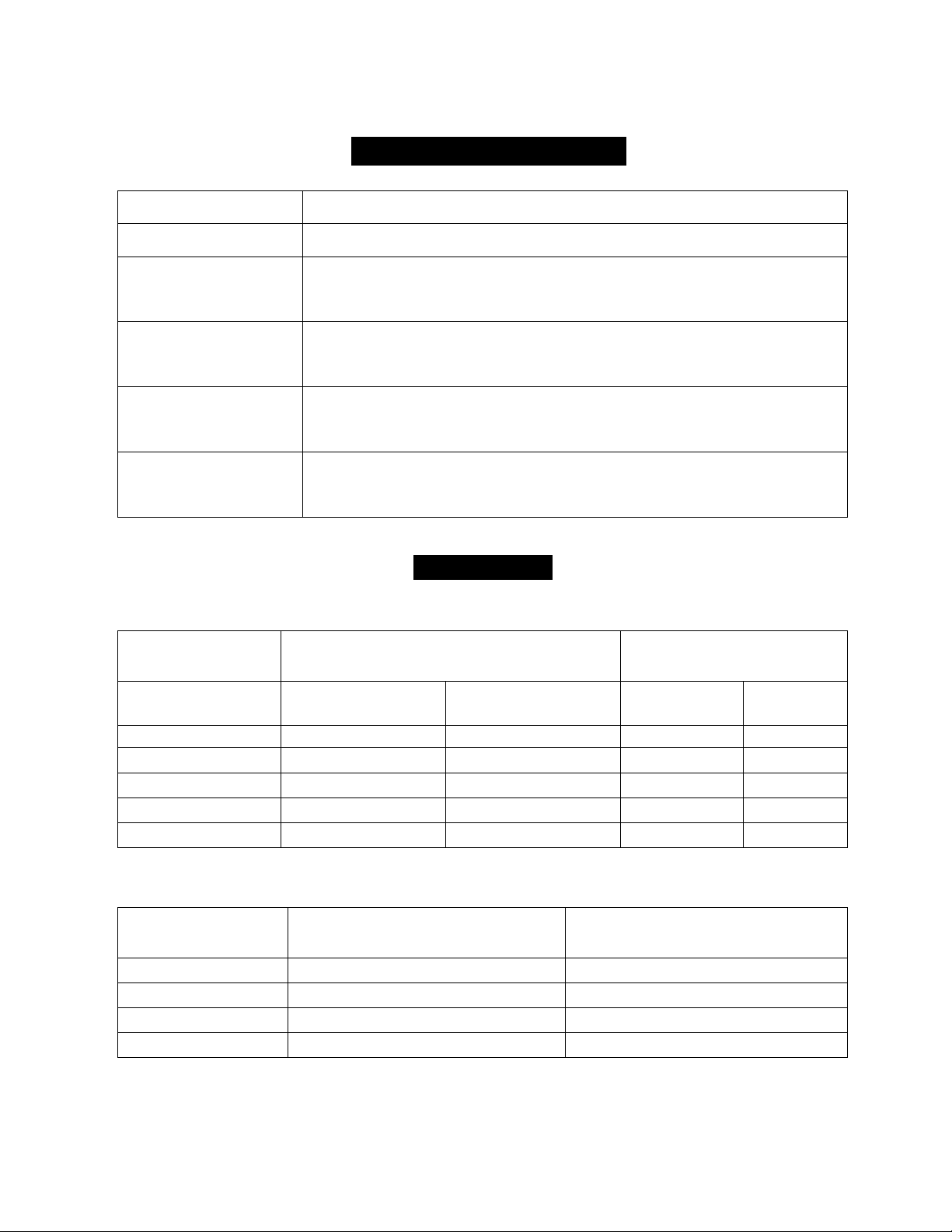
SPECIFICATION(S8000)
Rated line pulls
8000 lbs (35.56kN)
Gear reduction ratio
196:1
Motor
5.8hp / 4.3Kw(12V)
7.4hp / 5.5Kw(24V)
Overall dimensions
22" (L) x6.3" (W) x9.8" (H)
559(L)mmX160(W) mmX248(H)mm
Drum size
Ø2.48" (D) x 8.8" (L)
Ø 63(D) mm ×223(L) mm
Cable
Ø 21/64" (D) x 95'(L)
Ø 8.3mm (D) x29m (L)
DUTY CYCLE
Line speed and motor current (First layer)
Line pull
Line speed
ft/min (m/min)
Motor current Amps
(Max)
lb (kN)
12V
24V
12V
24V
0
36(11.0)
44.3(13.5)
50
35
2000(8.89)
17.4(5.3)
20.3(6.2)
125
90
4000(17.78)
13.1(4.0)
15.7(4.8)
200
140
6000(26.67)
10.5(3.2)
14.1(4.3)
260
150
8000(35.56)
8.2(2.5)
10.8(3.3)
310
200
Line pull and cable capacity
Layer of cable
Rated line pull per Layer
lb (kN)
Cable capacity per Layer
ft (m)
1
8000(35.36)
21.3(6.5)
2
6620(29.43)
46.9(14.3)
3
5650(25.12)
77.1(23.5)
4
4920(21.87)
95.1(29)
Page 27
25
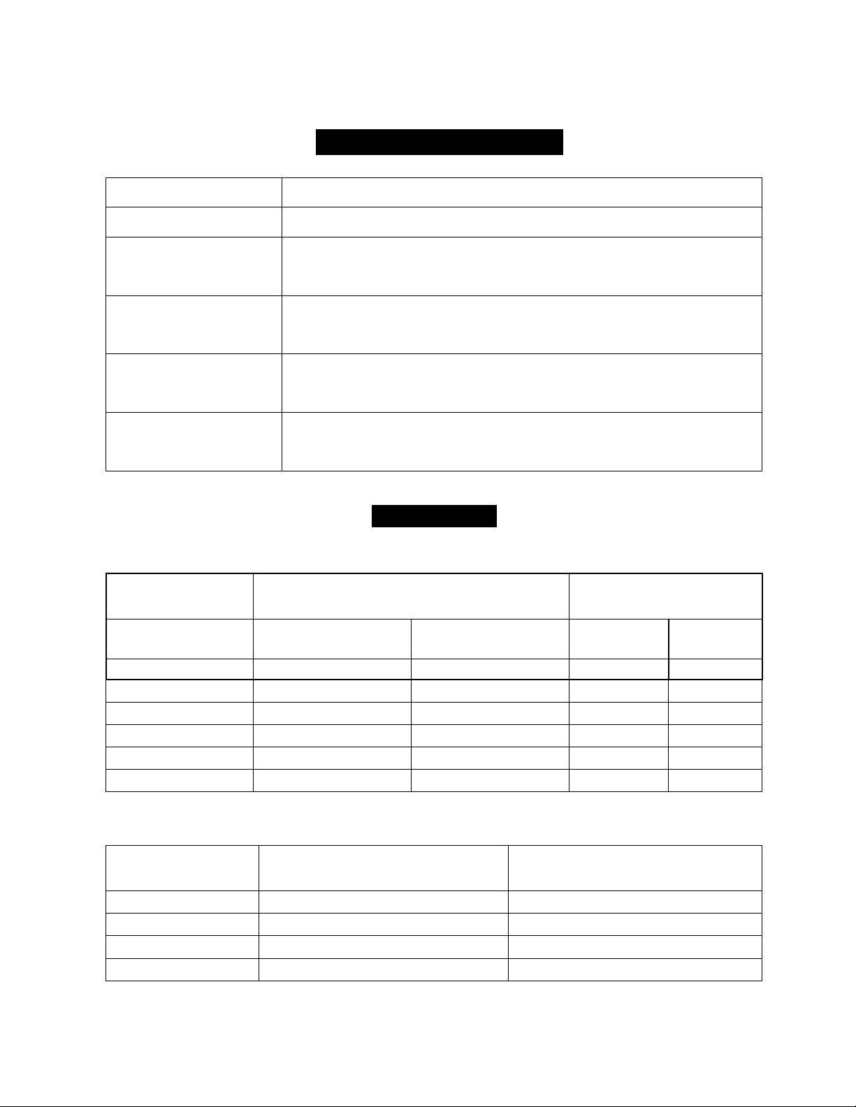
SPECIFICATION(S9500)
Rated line pulls
9500 lbs (42.23kN)
Gear reduction ratio
196:1
Motor
6.1hp / 4.6Kw(12V)
7.8hp / 5.8Kw(24V)
Overall dimensions
22" (L) x6.3" (W) x9.8" (H)
559(L)mmX160(W)mmX248(H)mm
Drum size
Ø2.48" (D) x 8.8" (L)
Ø 63(D) mm ×223 (L) mm
Cable
Ø 3/8" (D) x 85'(L)
Ø 9.2mm (D) x 26m (L)
DUTY CYCLE
Line speed and motor current (First layer)
Line pull
Line speed
ft/min (m/min)
Motor current
Amps (Max)
lb (kN)
12V
24V
12V
24V
0
36(11.0)
44.3(13.5)
50
35
2000(8.89)
17.4(5.3)
20.3(6.2)
120
90
3000(13.33)
15.4(4.7)
17.3(5.3)
150
105
6000(26.67)
10.5(3.2)
14.1(4.3)
260
150
8000(35.56)
8.2(2.5)
10.8(3.3)
300
200
9500(42.23)
6.5(2.0)
8.5(2.6)
355
225
Line pull and cable capacity
Layer of cable
Rated line pull per Layer
lb (kN)
Cable capacity per Layer
ft (m)
1
9500(42.23)
18(5.5)
2
7600(33.78)
39.4(12)
3
6200(27.56)
64(19.5)
4
5400(24.00)
85(26.0)
Page 28
26
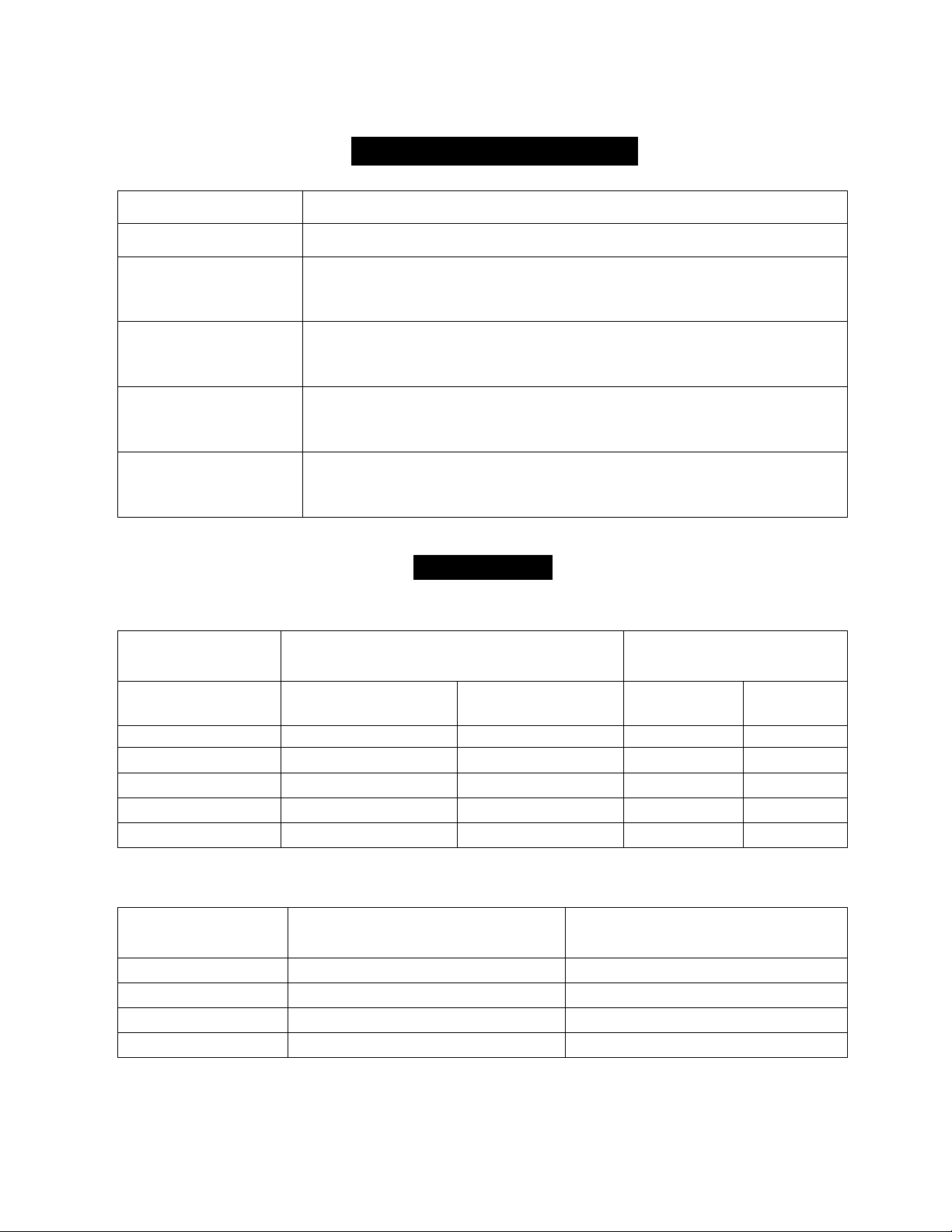
SPECIFICATION(S12000)
Rated line pulls
12000 lbs (53.34KN)
Gear reduction ratio
253:1
Motor
6.7hp / 5.0Kw(12V)
8.0hp / 6.0Kw(24V)
Overall dimensions
22" (L) x6.3" (W) x9.8" (H)
559(L)mmX160(W)mmX248(H)mm
Drum size
Ø2.48" (D) x 8.8" (L)
Ø 63(D) mm ×223(L) mm
Cable
Ø 13/32" (D) x 83.7'(L)
Ø 10.2mm (D) x 25.5m (L)
DUTY CYCLE
Line speed and motor current (First layer)
Line pull
Line speed
ft/min (m/min)
Motor current
Amps (Max)
lb (kN)
12V
24V
12V
24V
0
27.9(8.5)
36.1(11.0)
45
30
6000(26.67)
11.5(3.5)
12.1(3.7)
200
130
8000(35.56)
8.2(2.5)
10.5(3.2)
240
180
10000(44.45)
5.9(1.8)
8.9(2.7)
300
220
12000(53.34)
4.6(1.4)
7.9(2.4)
370
250
Line pull and cable capacity
Layer of cable
Rated line pull per Layer
lb (kN)
Cable capacity per Layer
ft (m)
1
12000(53.34)
15.1(4.6)
2
9533(42.38)
34.1(10.4)
3
7907(35.15)
57.7(17.6)
4
6755(30.03)
83.7(25.5)
Page 29
27
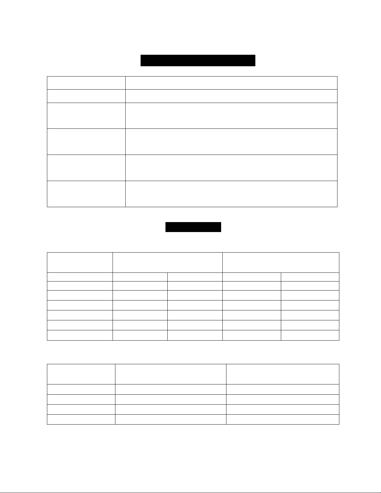
SPECIFICATION(S14500)
Rated line pulls
14500 lbs (64.45KN)
Gear reduction ratio
253:1
Motor
7.2hp / 5.4Kw(12V)
8.3hp / 6.2Kw(24V)
Overall dimensions
23.35" (L) x6.30" (W) x9.80" (H)
593(L) mm X 160(W) mm X 248 (H) mm
Drum size
Ø2.48" (D) x 8.8" (L)
Ø 63(D) mm ×223(L) mm
Cable
Ø 13/32" (D) x 83.7'(L)
Ø 10.2mm (D) x 25.5m (L)
DUTY CYCLE
Line speed and motor current (First layer)
Line pull
Line speed
ft/min (m/min)
Motor current
Amps (Max)
lb (kN)
12V DC
24V DC
12V DC
24V DC
0
27.9(8.5)
36.1(11.0)
45
30
6000(26.67)
11.5(3.5)
13.8(4.2)
200
130
8000(35.56)
7.87(2.4)
10.5(3.2)
245
160
10000(44.45)
5.57(1.7)
8.9(2.7)
310
190
12000(53.34)
4.92(1.5)
7.9(2.4)
380
230
14500(64.45)
2.6(0.8)
4.26(1.3)
460
300
Line pull and cable capacity
Layer of cable
Rated line pull per Layer
lb (kN)
Cable capacity per Layer
ft (m)
1
14500(64.45)
15.1(4.6)
2
11519(51.2)
34.1(10.4)
3
9556(42.48)
57.7(17.6)
4
8163(36.28)
83.7(25.5)
Page 30
28
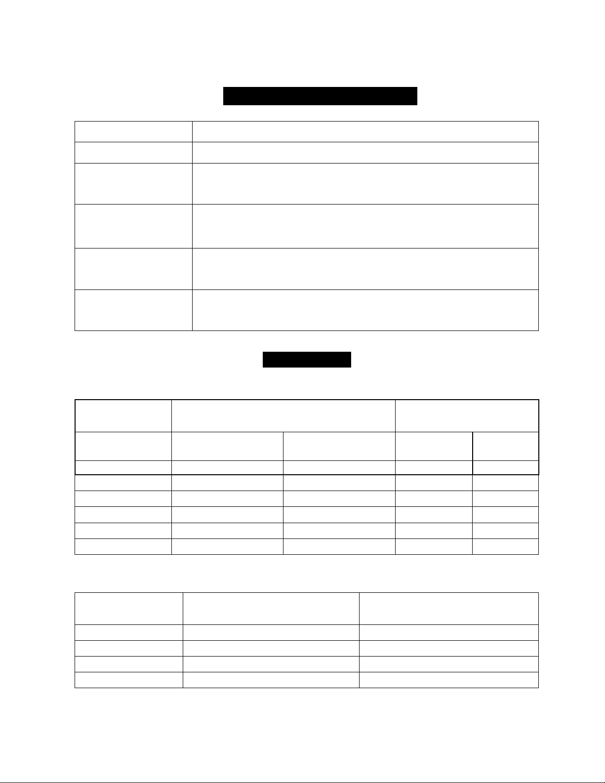
SPECIFICATION(S9500SD)
Rated line pulls
9500 lbs (42.23kN)
Gear reduction ratio
196:1
Motor
6.1hp / 4.6Kw(12V)
7.8hp / 5.8Kw(24V)
Overall dimensions
18" (L) x6.3" (W) x9.8" (H)
456(L)mmX160(W)mmX248(H)mm
Drum size
Ø2.48" (D) x 4.7" (L)
Ø 63(D) mm ×120 (L) mm
Cable
Ø 3/8" (D) x 45.9'(L)
Ø 9.2mm (D) x 14.0m (L)
DUTY CYCLE
Line speed and motor current (First layer)
Line pull
Line speed
ft/min (m/min)
Motor current
Amps (Max)
lb (kN)
12V
24V
12V
24V
0
36(11.0)
44.3(13.5)
50
35
2000(8.89)
17.4(5.3)
20.3(6.2)
120
90
3000(13.33)
15.4(4.7)
17.3(5.3)
150
105
6000(26.67)
10.5(3.2)
14.1(4.3)
260
150
8000(35.56)
8.2(2.5)
10.8(3.3)
300
200
9500(42.23)
6.5(2.0)
8.5(2.6)
355
225
Line pull and cable capacity
Layer of cable
Rated line pull per Layer
lb (kN)
Cable capacity per Layer
ft (m)
1
9500(42.23)
9.8(3.0)
2
7600(33.78)
24.6 (7.5)
3
6200(27.56)
42.7(13.0)
4
5400(24.00)
45.9 (14.0)
Page 31
29
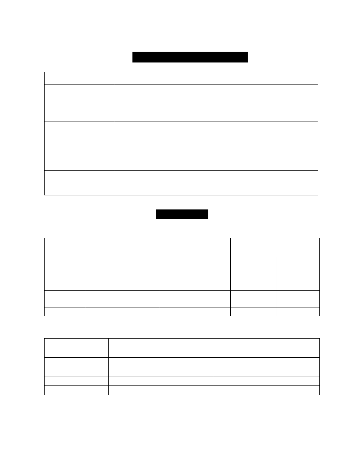
SPECIFICATION(S9500HS)
Rated line pulls
9500 lbs (42.23kN)
Gear reduction ratio
121.7:1
Motor
8.6 hp / 6.4kW (DC 12V)
10.7hp /8.0kW (DC 24V)
Overall dimensions
23.35" (L) x6.30" (W) x9.80" (H)
593(L)mmX160(W)mm X 248 (H) mm
Drum size
Ø2.48" (D) x 8.8" (L)
Ø 63(D) mm ×223(L) mm
Cable
Ø 3/8" (D) x 85'(L)
9.2mm (D) x 26m (L)
DUTY CYCLE
Line speed and motor current (First layer)
Line pull
Line speed
ft/min (m/min)
Motor current
Amps (Max)
lbs (kN)
12V
24V
12V
24V
0
68.9(21)
82.0(25)
45
31
4000(17.78)
17.7(5.4)
19.7(6.0)
260
150
6000(26.67)
12.1(3.7)
16.1(4.9)
350
210
8000(35.56)
9.51(2.9)
13.12(4.0)
440
260
9500(42.23)
8.86(2.7)
11.81(3.6)
520
300
Line pull and cable capacity
Layer of cable
Rated line pull per Layer
lbs (kN)
Cable capacity per Layer
ft (m)
1
9500(42.23)
15.1(4.6)
2
7600(33.78)
34.1(10.4)
3
6200(27.56)
57.7(17.6)
4
5400(24.00)
85.3(26.0)
Page 32

30
Limited lifetime with 3 year on electrical
Limited Lifetime Warranty for WARRIOR WINCHES
Winch Solutions are the sole distributors of WARRIOR WINCHES.
Winch Solutions (“seller” or winch solutions) warrants to the original retail buyer only
(“Buyer”) that any mechanical component of a genuine WARRIOR WINCH (“product”)
is free of defects in material and workmanship for the lifetime of the winch.
The electrical components (including the motor, contactor, and switches) will be free
of defects in material and workmanship for a period of (3) three years (36 Months)
from the original purchase provable date of purchase.
Any product Winch Solutions determines to be defective will be repaired or replaced at
Winch Solutions sole discretion without charge to the Buyer upon Buyer’s compliance
with this procedure. Seller or its Authorized Agent may make reasonable charges for
parts and for labour for repairs not covered by this Lifetime Limited Warranty. The
warranties set forth herein are exclusive and in lieu of all other warranties, whether
oral or written, express or implied.
All purchases must be registered. Any product that has not been registered will
be covered by the standard 1 year warranty.
To obtain service under this warranty, the Buyer shall mail, ship or otherwise deliver to
the address noted below, at the Buyers expense; (1) the Product, (2) a written
description of the problem, (3) Buyers name, address and contact number, (4) copy of
the original purchase receipt.
The Warranty does not cover the cost of labour or transportation/shipping charges for
the replacement or installation of defective parts.
This warranty does not apply to defects of the Product caused by; (1) normal wear
and tear, (2) failure to comply with any installation or maintenance instructions
provided by the Seller, including but not limited to subjecting the product to loads in
excess of the loads listed in any instructions, Owners Manual or as detailed upon the
Sellers website, (3) commercial or industrial use, (4) alteration or modification by any
parties other than the Seller, (5) misuse, abuse, neglect, accidents, Acts of God,
terrorism or (6) other causes beyond the control of the Seller after delivery of the
Product to the Sellers Authorized Agent.
This Warranty does not cover cables, synthetic ropes, fairleads or exterior finishes
Winch Solutions shall not be responsible or liable for any indirect or consequential
damages. These consequential damages may include, but are not limited to, lost
profits or loss of use and down time.
Winch Solution reserves the right to change the Product design without notice. Winch
Solutions reserves the right to replace any part or whole unit with a newer design of
the same function.
Page 33
31
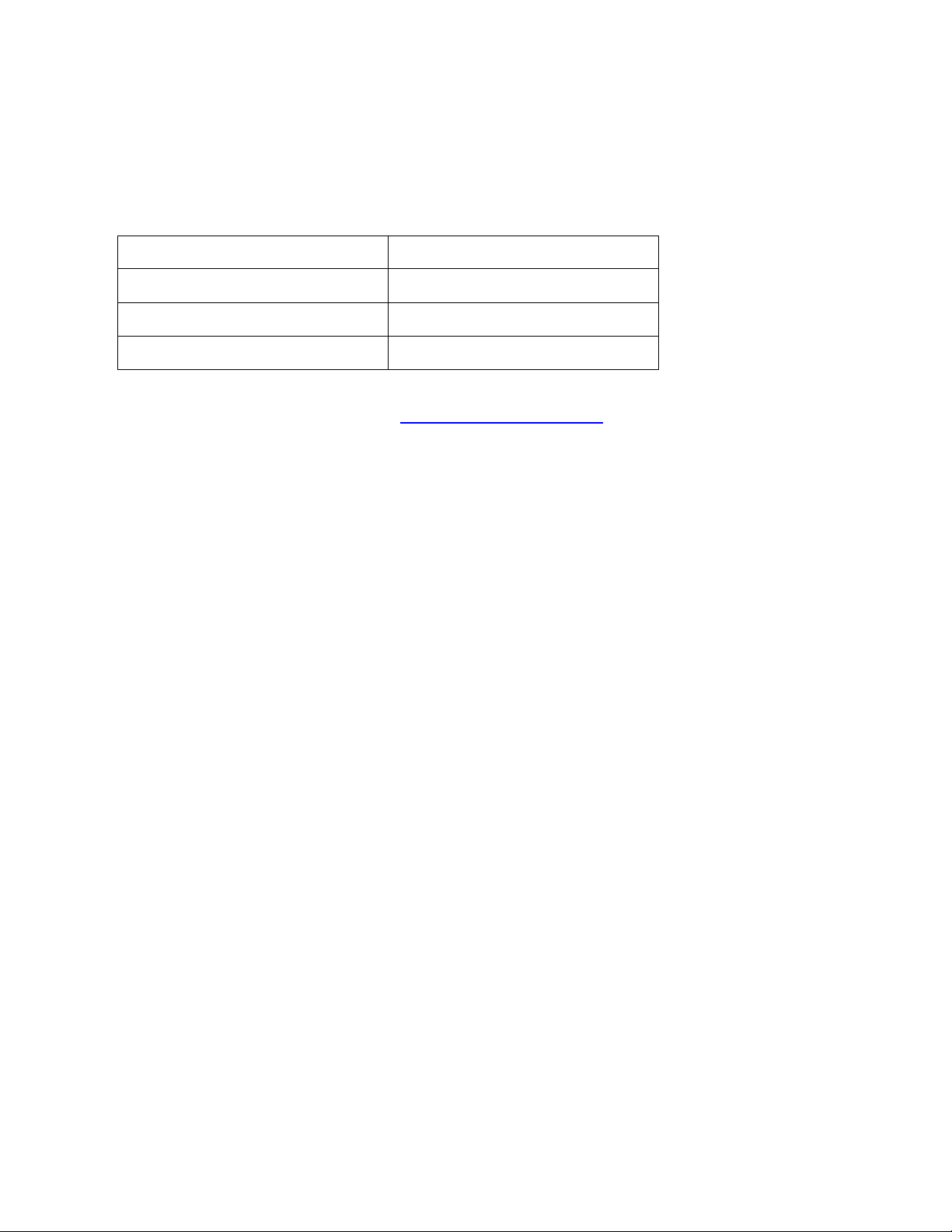
Please ensure you record the information below:
Distributor
Date of Purchase
Invoice No
Serial No
Please register your Winch at www.warriorwinch.co.uk , any product that is not
registered will not be covered by the lifetime warranty.
In the unlikely event you experience problems, contact the distributor with this
information.
 Loading...