

Page 1
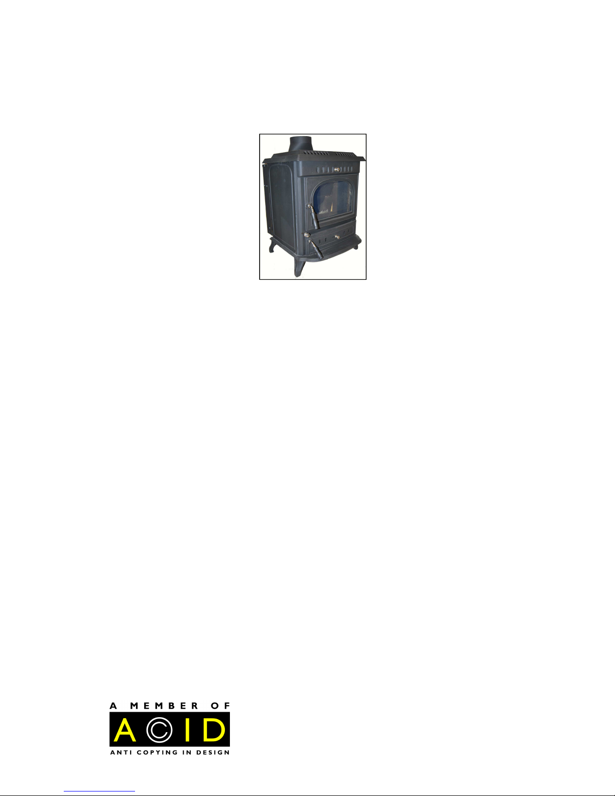
Congratulations on your decision to own an advanced high quality and desirable Multi-Fuel
WARRIOR Stove. This Stove has been manufactured and designed in our factory from
premium grade materials to give you many years of excellent service when correctly
installed, operated and maintained. The main body is constructed from premium grade cast
iron, this is sand cast the traditional time honoured way by experts from freshly mined pig
iron. Cast Iron is the best material known for retaining and radiating heat, recycled scrap
iron is not used for any part of a WARRIOR Stove.
Please carefully and thoroughly read this manual prior to any installation or lighting of your
new stove.
If you have any questions regarding this stove which are not mentioned in this manual then
please contact the vendor of the stove or our head office, details below.
Manufactured by:
WARRIOR Stoves Ltd. (HEAD OFFICE)
Chapel Road
Tuckingmill
Camborne
Cornwall
UK. TR14 8QY
Tel: 01209 711115
Fax: 01209 612322
E-mail: info@warriorstoves.co.uk
Web: www.warriorstoves.co.uk
Please keep this manual for future reference. It has been produced for the WARRIOR
Stoves Aidan stove and may not be copied in whole, part or be used for any purpose apart
from which it is intended without express and written permission from a WARRIOR Stove
employee.
WARRIOR Stoves Ltd.
Manual for:Aidan Multi-Fuel Stove
Model no: WSDAID
Page 2

TECHNICAL DATA 1
SAFETY 2
STOVE LOCATION 3
STOVE ASSEMBLY 4
STOVE INSTALLATION. (Including Chimney Guidance) 5-12
STOVE OPERATION 13-16
STOVE AND CHIMNEY MAINTENANCE 17-18
TROUBLESHOOTING 19
PARTS DIAGRAM 20
LIST OF USEFUL ADDRESS’S 21
INSTALLATION RECORD 22
MAINTENANCE RECORD 23
GUARANTEE 24
OTHER PRODUCTS FROM WARRIOR STOVES LTD. 25
CONTENTS
Page 3
2
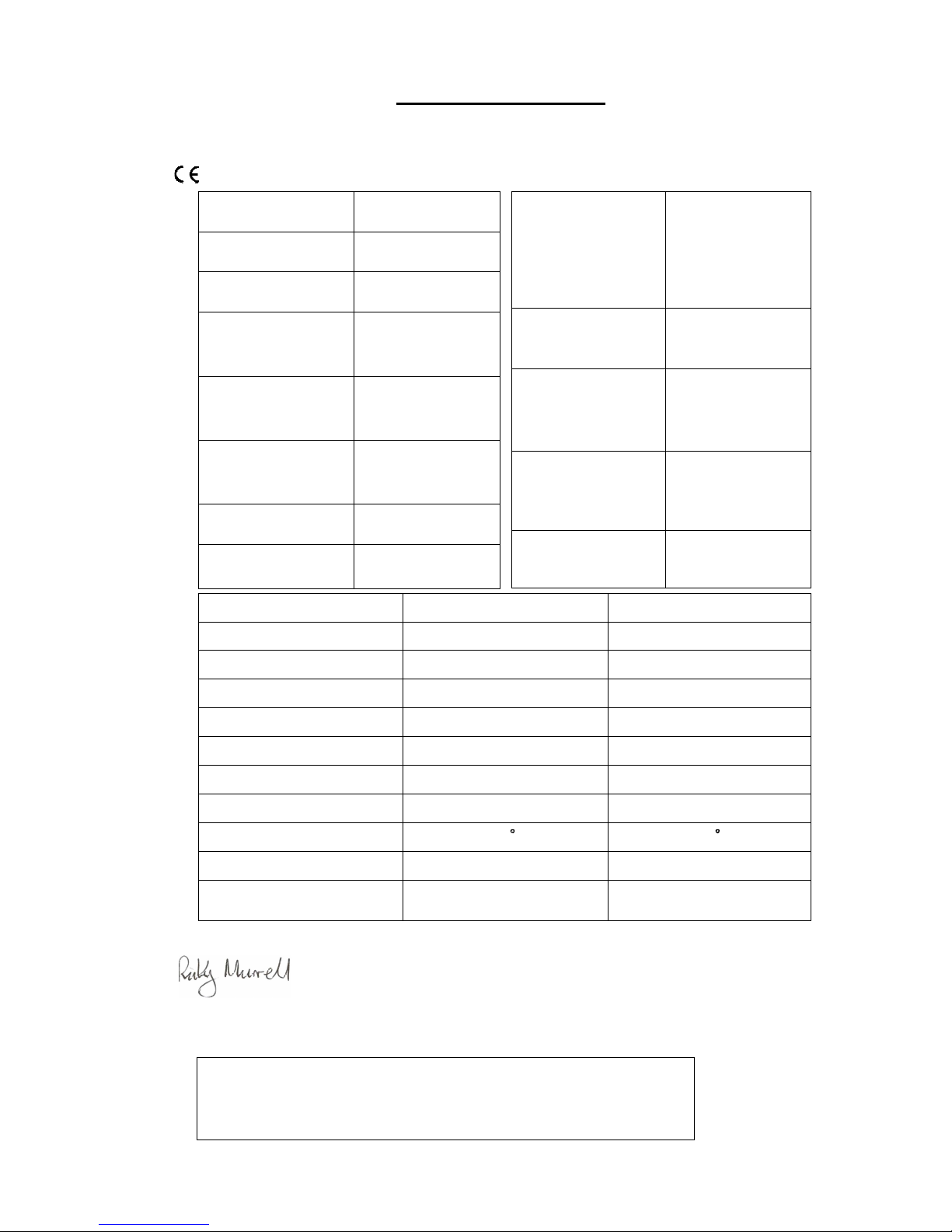
TECHNICAL DATA
WARRIOR Stoves:Aidan WARRIOR Stoves Ltd.
Model No:WSDAID Chapel Road, Tuckingmill
Continuously rated Multi-Fuel Stove Camborne, Cornwall.
Approved to EN13240 TR14 8QY.
This information is true.
Ricky MURRELL
WARRIOR Stoves Ltd
Authorised Signatory for this stove in the United Kingdom and Republic of Ireland
Useful Information:
1Kw ≈ 3412.14BTU’s (British Thermal Unit)
1cm ≈ 0.3937” / 25.4mm ≈ 1”
1Kg ≈ 2.2046 lbs.
Height (mm) 790
Width (mm) 620
Depth (mm) 600
Height to centre of
rear flue (mm)
445
Depth from back to
centre of flue (mm)
130
Flue Diameter Req.
(mm)
150
Net weight (Kg) 210
Gross weight (Kg)
[Packed]
220
Minimum distance to
Combustible surfaces.
Top 800mm
Side 450mm
Rear 1200mm
Type of boiler and
method of construction
N./A.
Boiler maximum
operating water
temperature
N./A.
Boiler maximum
operating pressure in
bar.
N./A.
Boiler test pressure in
bar
N./A.
Test Type NOMINAL OUTPUT NOMINAL OUTPUT
When fuelled with SOLID MINERAL WOOD
Refuelled every 5Hrs 0.75Hrs
Flue Gas Mass Flow 10.5g/s 9.2g/s
With a flue draught of 12Pa 12Pa
Output to room 8.8kW 11kW
Output to water N./A. N./A.
Mean Efficiency 67.8% 72.1%
Mean Flue Temperature 343 C 386 C
Mean CO concentration at 13% O 0.19% 0.37%
Test by: GASTEC@CRE IN THE UK GASTEC@CRE IN THE UK
1
Page 4

SAFETY
Safety is of paramount importance when deciding on locating, moving, installing, operating
and maintaining the stove.
Ensure that this manual is read and understood prior to installation or commissioning the
first fire.
This Stove must be installed in accordance with all local regulations including those
referring to national and European standards. WARRIOR Stoves recommend that a
competent person such as a HETAS approved installer is used for installation. HETAS
details are listed near the back of this manual for further reference. Most stove retailers will
be able to assist in advising a competent person for installation.
WARRIOR Stoves installation instructions cannot be taken as conforming to all standards in
all areas and also cannot account for changes in legislation.
This Stove must not be modified without the express and written permission of a WARRIOR
stoves employee. Alterations not authorised by WARRIOR Stoves Ltd. will terminate the
guarantee and may also be potentially dangerous.
Numerous further safety procedures are listed throughout this manual specific to separate
tasks of installation and usuage, etc. For your safety and others around you ensure these
procedures are adhered to.
2
Page 5
The floor which the stove is to be located on must have an adequate load-bearing capacity. If
the floor does not meet this requirement then suitable measures in accordance with building
control regulations need to be taken.
This stove has passed the requirements of building regulations so that it only requires a 12mm
Thickness hearth.
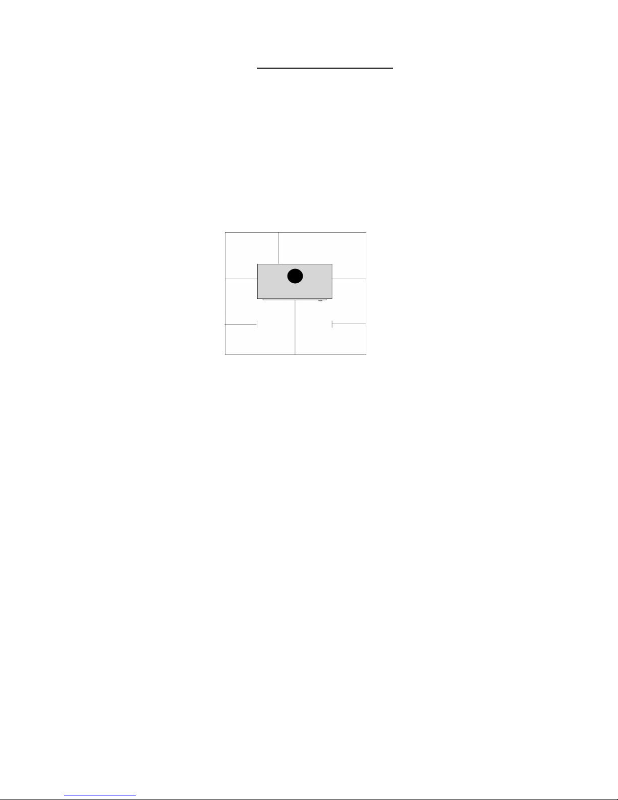
The stove must be located on a solid non combustible hearth/surface with the minimum
dimensions extending from the perimeter of the stove as shown below:
The stove surfaces must have a minimum distance away from any combustible materials as
listed in the technical data section of this manual.
Single wall fluepipes must be more than three times the diameter of the fluepipe away from
combustible materials i.e. 125mm (5”) Fluepipe should be a minimum of 375mm (15”) away.
For further assistance regarding flue pipe & liners please contact your stove dealer, approved
installer, building control officer or Midtherm Flue Systems Ltd. (Details listed at rear of this
manual). The complete range of Midtherm flues and ancillary components are available from
your stove retailer.
Further advice regarding chimney and flues for this stove is detailed in the Installation
section of this manual.
This stove must have its own dedicated chimney or flueway. It is not suitable for installing
into a shared flueway. The stove must always have a permanent free air supply into the room it
is being installed into. For Stoves rated above 5KW a permanent unobstructed air vent is
required. This vent should be in the same or adjoining room as the stove and must be
connected directly to the outside air, where possible locate the vent close to the stove to
confine draughts. The vent size should be a minimum of 550mm2 per KW over 5 KW, i.e.
A stove rated at 11kw would need a minimum vent size of 3,300mm2 for modern properties
(Generally only since 2008) with Design Air Permeability greater than or equal to 5.0Mtr3/
(h.m2) then 550mm2 is required per kW output. It is always advisable to install a vent if there
is not one present for a stove rated under 5Kw and like wise it is better to install a vent larger
than the minimum recommended size. This is to account for the possibility of operating the
stove at more than its rated output.
Extractor fans operating in the same room or air space as the stove may cause problems with
the air supply to the stove which in turn may cause problems with chimney draw.
Your approved installer or building control officer should be familiar with all these aspects of
where the stove may be installed.
STOVE LOCATION
A=150mm
B=225mm
C=150mm
D=150mm
3
A A
B
C
Front of stove
D
D
These distances may be
reduced if the Hearth
adjoins a non
combustible wall.
Page 6

STOVE ASSEMBLY
Care should be taken when unpacking and assembling your stove. Stoves are heavy and
therefore due consideration is required in lifting and moving into the final location. Where
possible use a sack truck or trolley and obtain assistance rather than struggling or risking
personal injury. You may find that it is easier to open the stove and remove loose items to
reduce the weight of the stove. The following are useful techniques for manual lifting:
•
Keep the stove close to your waist with your head facing forwards and your back
straight.
•
Do not twist at the waist, reposition your feet as necessary.
•
Bend both legs to maintain stability.
•
Avoid twisting your back, leaning forwards or sideways when handling the stove.
•
Smooth and controlled movement will help to keep the stove under control, avoid
snatching or jerking when moving the stove.
•
Always grip with the palms of your hands preferably wearing gloves to provide
additional grip, do not rely solely on fingertips for support.
•
Wear suitable clothing, avoid wearing ties and other loose items that could get caught
in the stove. The use of protective footwear with steel toecaps is advisable.
This stove requires little assembly prior to moving into it’s final location.
Firstly carefully unwrap the stove and the contents either on the original packing or onto a
sheet of plyboard or similar in order to minimize the risk of damage to the furnishings
below.
After unpacking remove the loose items from the stove which require fixing, these parts
should be: The Legs, the Stove Outlet and the Stove Outlet Blanking Plate and the Handles.
These parts should be easily identifiable from the exploded parts diagram listed near the end
of this manual. Attach the legs to the base of the stove with the bolts provided, these bolts
are already attached at the base of the stove in the correct location. Tighten with firm
pressure without over tightening.
The Stove Outlet and the Stove Outlet Blanking Plate again require bolting into the correct
position, (determined by flue exit, possible from the Top or the Rear of this stove) with the
bolts provided. Prior to fixing a smear of fire cement and or heat resistant rope is
recommended to ensure the join is airtight. See the note in the Stove Installation Section
regarding the caustic nature of fire cement, again do not over-tighten the bolts. The handles
simply bolt on.
Inside the Stove there should be the following:
•
Grate with Fuel Retainers.
•
Ashpan & Ashpan removal Tool.
•
Baffle/Throat Plate.
•
Side Cast/Refractory Brick Linings.
•
Rear Cast/Refractory Brick Linings, please note for Back-Boiler Model Stoves these
will not be in the stove, they are replaced by the Back-Boiler.
All of these internal parts should be easily identifiable from the exploded parts diagram
printed near the rear of this manual. If any parts have become dislodged during transit then
it should be straightforward to re-locate in their respective places. Should parts need bolting
back in place, do not over tighten.
If you have any questions regarding the parts within the stove which are not mentioned
above then please contact the vendor of the stove or our head office.
4
Page 7

STOVE INSTALLATION
Prior to any installation being undertaken ensure that all intended work conforms to Building
Regulations or Standards and any local laws including those referring to national and
European Standards. The following are applicable:
England & Wales > Building Regulations (2001) > Document J particularly relevant.
Scotland > Building Standards (2001) > Section F particularly relevant.
Northern Ireland > Building Regulations (1990)
Republic of Ireland > Building Regulations (1997) > Document J particularly relevant.
Isle of Man > Building Regulations (2003) > Part J particularly relevant.
The above listed Regulations and Standards are subject to change and should be confirmed
prior to installation.
Installation should be carried out avoiding any risk to yourself, the occupiers and any pets
etc. Fire cement used during installation should be used in accordance with the instructions
on the tub or cartridge. It is classed as an irritant so protective gloves are recommended.
If the stove requires touching up/repainting then ensure adequate ventilation is available as
most high temperature resistant paints release unpleasant odours. Always follow the stove
paint manufacturers instructions. The stove must not be alight whilst re-painting.
If the stove is being installed into an existing chimney ensure that protective eye ware is
worn during inspection and whilst attending to any remedial work that may be required.
In the case of installing into old Chimneys particular attention should be given to the
possibility of disturbing asbestos. There are many types of asbestos, the three most common
are white (chrysotile), brown (amosite) and blue (crocidolite). All three types are hazardous,
particularly blue and brown, however asbestos cannot just be identified by its colour. Asbestos should only be removed by a registered specialist.
Chimney & Flue Guidance
Effective Chimneys require numerous considerations. The purpose of a chimney is to
provide an up draught to ensure the safe removal of the products of combustion from the
stove to the outside air.
To maintain a safe and efficient up draught the chimney/flueway must conform to the
following:
•
The Chimney/Flue should be totally free from defects and not leak at any point
through to its terminal. A smoke test should be done to confirm this, a guide to smoke
testing is listed further on in this section of the manual.
•
The Chimney/Flue must have a height of no less than 4.5 Meters from the top of the
stove to a suitable Chimney terminal.
•
The Terminal of the Chimney/Flue must be in a position where the products of
combustion can freely discharge without preventing a hazard whatever the wind
conditions . See the diagram further on in this section regarding flue outlet positions.
5
Page 8

•
The Chimney/Flue diameter must never be decreased in size from the stove. It is good
practise to increase the chimney/flue diameter by 25 or 50mm, this will maintain a
suitable draw in the event of the flue way becoming partially blocked due to possible
tar build up in the chimney.
•
The Chimney diameter must be no less than 125mm diameter if only burning
smokeless fuels, for any other fuel type this must be increased to a minimum of
150mm.
•
The Chimney/Flue should be kept as straight as possible. Offsets in the flue way
should be kept to a minimum and should not exceed 45 degrees except when
connecting to the rear off the stove, a 45 or 90 Degree Tee should be used for these
installations completed by a soot box at the base.
•
No more than 4x45degree elbows should be installed, when using a 90 tee at the rear
of the stove this would be classed as 2x45degree elbows.
•
90 degree elbows are not suitable for this stove.
•
When connecting the flue to the rear of the stove the maximum horizontal run should
not exceed 150mm.
•
Provision must be made for cleaning the entire length of the chimney/flue other than
through the stove.
•
The Flue way must be kept warm to ensure a suitable up draught.
There are numerous ways of installing this stove including situations where a chimney is not
present in the building. The Chimney/Flue used should comply with the following:
Connecting Fluepipes (For connecting directly onto the stove outlet):
•
Vitreous Enamelled Steel Pipe> BS 6999: 1989 (1996)
•
Stainless Steel grades 1.4401, 14404, 14432 or 1.4436(Minimum flue wall thickness of
1mm)>BS EN10088-1:1995
•
Cast Iron Flue Pipes>BS41:1973 (1998)
•
Mild Steel Flue Pipes (Minimum flue wall thickness of 3mm)>BS 1449:Part1:1991
Fluepipe/Chimney Linings:
•
Concrete Chimney Blocks> BS EN 1858: 2003
•
Clay Chimney Blocks> BS EN 1806: 2000
•
Concrete Flue Linings> BS EN 1857: 2003
•
Clay Flue Linings> BS EN 1457: 1999
•
Factory Manufactured Metal Chimney> BS EN 1856-1: 2003
•
Tested Linings approved by a Notified Body.
Where applicable the Midtherm Flue Pipe available from WARRIOR Stoves dealers
conforms to the above standards.
6
Stove Installation Continued.
Page 9
All Installations:
Place the stove carefully on its hearth and ensure it is stable and level. The spigot (male) end
of the Connecting Flue Pipe must fit inside the stove outlet and be sealed with fire cement.
The socket (female) end faces away from the stove. This is to ensure that any condensate,
etc. will run into the stove and dissipate rather than spoil the appearance of the final
installation. See diagram below:
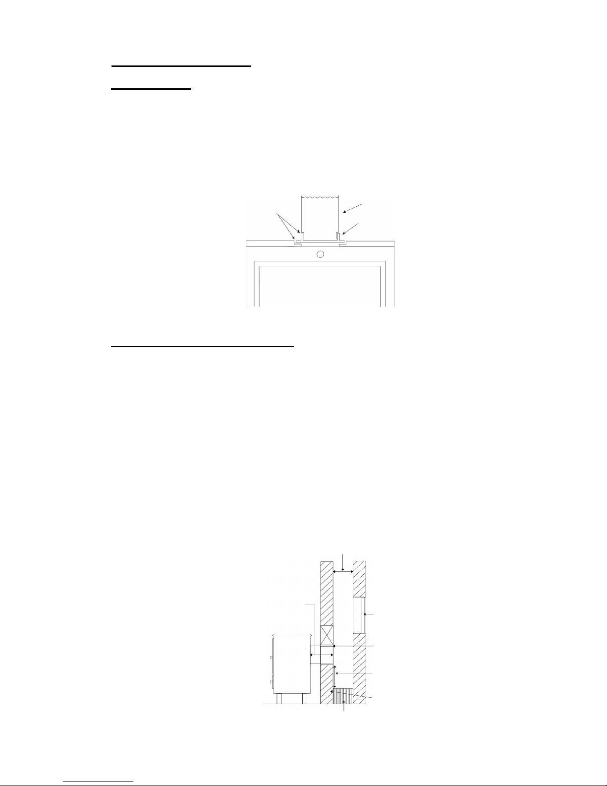
For connecting into existing Chimney:
The Chimney should be swept prior to installation and smoke tested to ensure it is sound.
The Chimney must not have any hollow sections present, these should be filled to ensure
that any soot or tar, etc. does not build up which may present problems when sweeping the
chimney. Hollow sections within the chimney may also present problems with the chimney
draw. The connecting flue pipe must be sealed to the chimney with fire cement and high
temperature resistant rope as required. This is usually done into a register (Blanking) plate
with an access door/hatch to enable chimney sweeping. Particularly large chimneys may
require lining as the flue temperature may not get warm enough to provide a suitable
up-draught.
Use fire cement and stove
rope to ensure air tight seal.
Connecting Fluepipe
Stove Outlet
Fire retardant
Rope seal required
Build up opening
Soot/Access Door
Fill Void
Minimum diameter should be no less than the outlet size of the stove, 25to 50mm larger is
ideal. Where the stove outlet is less than 150mm this diameter should be no less than 125mm
when only burning smokeless fuels or a minimum of 150mm for any fuel types.
Maximum150mm
Horizontal flue.
7
Stove Installation Continued.
Allow area for collecting soot build up.
Minimum distance should be no less than
The outlet diameter of the stove.
Page 10

Some typical installations are shown as following:
If the chimney is not sound, i.e. found to be leaking after a smoke test then the chimney must
either be repaired or a flexible liner may be used, ensure the liner is the correct type for
Multi-Fuel applications. See diagram below:
Register plate.
TOP FLUE OUTLET
Access door
The register plate must be 1.5mm thick rust
resistant steel or heat resistant board. The
Flue Pipe must be 3 times it’s diameter
away from combustible materials. For
example 150mm Flue Pipe must be 450mm
away from combustible materials.
FLUE
Sealed door to
access chimney
for sweeping &
inspecting.
Support Bracket for Flexible Liner.
Support Bracket for the
connecting fluepipe
Flexible Liner
Register Plate
SW to TW Adapter
Maximum Recommended distance is
1.5mtrs of connecting fluepipe to existing
chimney or Twin Wall Class 1 system
8
Stove Installation Continued.
It is recommended that
this area is insulated or
backfilled.
Vitreous Fluepipe with
stainless access door.
Page 11

For Installations where no Chimney exists:
The Connecting flue pipe from the Stove should connect to the Twin Wall Insulated flue
pipe, ensure this flue pipe is the correct type for Multi-Fuel applications. The HT-Plus flue
pipe manufactured by Midtherm is suitable and available from WARRIOR Stoves dealers.
This flue pipe requires a minimum 50mm clearance from combustible materials and should
not be joined in a wall or floor. Where this flue pipes passes through a combustible floor a
ventilated fire stop kit must be used.
Some typical installations are shown as following:
Rain cap/Cowl
600mm minimum
One load bearing support every 6Mtrs
maximum. This should be increased if
elbows are used in the installation.
One wall band every 2Mtrs Max.
One every 1.5Mtrs if on an incline.
Access for soot removal
o
Maximum horizontal
150mm
Access for
soot removal
600mm
minimum
Support Collar
Fire Stop Spacer
Radiation Shield
Fire Stop Spacer
Twin Wall Flue Pipe must
start at least 425mm below
combustible surface.
45 degree elbow
9
Stove Installation Continued.
o
45
Page 12

All Installations:
The Chimney/Terminal Outlet must be no lower than the minimum positions shown in the
diagram below:
For terminations above easily ignited surfaces i.e. thatched roofs then minimum outlet
positions are shown below, this diagram needs observing in conjunction with the above
diagram:
Upon completion of the installation the Chimney/Flue must be smoke tested prior to the
stove being lit. Smoke pellets are available from your WARRIOR Stoves dealer.
Following is a complete Smoke Test Guide:
A
B
C
D
Point where flue passes through weather surface (Notes
1,2)
Clearance to flue outlet
A At or within 500mm of the ridge. At least 600mm above the ridge.
B Elsewhere on a roof
(Whether pitched or flat)
At least 2300mm horizontally from the nearest point on the
weather surface and:
A) at least 1000mm above the highest point of intersection of
the chimney and the weather surface; or
B) at least as high as the ridge
C Below (on a pitched roof) or within 2300mm hori-
zontally to an open able roof light, dormer window
or other opening .
(Note 3)
At least 1000mm above the top of the opening.
D Within 2300mm of an adjoining or adjacent building,
whether or not beyond the boundary.
(Note 3)
At least 600mm above the adjacent building.
Notes
1) The weather surface is the building external surface, such as its roof, tiles or external walls.
2) A flat roof has a pitch less than 10 degrees
3) The clearance given for A or B, as appropriate, will also apply
Outlets should be above the
shaded areas.
Area Location of flue outlet
At least 1800mm vertically above the weather surface and at least 600mm above the ridge
B At least 1800mm vertically above the weather surface and at least 2300mm horizontally from the
weather surface.
1800mm
1800mm
600mm
At least
2300mm
B B
10
Stove Installation Continued.
o
Page 13

Smoke Test Guide
These are two Primary purposes for smoke testing, the first test is to discover any major
defects which can cause leakage of fumes through a chimney or flue structure during normal
operation. The second is to test the draw in the appliance.
If in doubt about the condition of a chimney, especially when an old chimney is to be used
after a long period of being unused, it is recommended to have it smoke tested. This is
particularly relevant for chimneys constructed prior to the 1965 Building Regulations which
require all new chimneys to be built with a suitable flue liner to protect the chimney
structure . Smoke Testing should also be carried out during construction of traditional
masonry chimneys and on all completed chimney installations.
A smoke test should be done by a competent person using the following procedures which
are based on recommendations in British Standard BS5440-1:2008. A slightly different
procedure is required for testing flues for gas appliances.
It should be remembered that the pressure of smoke from a test is far greater than that of a
chimney during normal use. Consequently minor smoke leakage may occur in joints of a
traditional masonry chimney or connections between prefabricated metal chimneys and flue
pipes. Minor leakage detected should not be a major risk when the appliance is used,
providing that it does not indicate a fault that could get worse. Remedial work will be
required if heavy leakage is seen. The most likely problems are broken components,
incorrect fitting or incomplete joining of flue liners.
Smoke Test 1: Testing Air Tightness of Chimney
•
Ensure appliance is not alight and all doors and windows in the room are closed.
•
If there is a solid fuel appliance or open fire appliance fitted at the base or the bottom
of the chimney, heat the inside of the Appliance/Fireplace chamber with a blow Lamp,
gas stove or similar device for approx 10 minutes, a longer warming up time may be
needed with wet or cold flues. This will establish a flue draw to stimulate real
conditions. It should be realised that neither of these methods create the same
temperatures or volume of hot gases that would normally be created whilst the
appliance is in use. If the flue is to be used with a gas burning appliance, the smoke
test should be carried out before the fire is fitted and the flue warmed with a blow lamp
for only 5 minutes, or longer if the flue is cold.
•
For testing flues to be used with a solid fuel appliance place one smoke pellet with a
minimum burn time of 60 seconds producing 15 Mtr3 of smoke on a flat surface that
cannot be harmed by heat in the opening at the base of the flue or in the appliance if it
is fitted. Always follow the pellet manufacturer’s safety instructions.
•
Ignite the top edge of the pellet and when smoke appears seal the opening with a board
or plate sealed at the edges. If a solid fuel appliance is fitted, close all doors, ash
pit covers and vents. Do not seal off the base of the flue or opening if testing a flue for
a gas appliance.
•
Check that the smoke rises freely out of the correct flue. When smoke begins rising
out of the top of the chimney, seal the top of the flue, terminal or pot, if appropriate
use an inflated football, bladder or plastic bag sealed in position with tape. Do not seal
the top of the flue if it is to be used with a gas appliance.
•
Examine the full length of the chimney for any leakage of smoke such as the joints for
metal flues. If possible check for signs of leakage from wall cavities at the sides and
back of the chimney, if it is built into a wall, also check for leakage at openings around
11
Page 14

If smoke is seen establish the point of leakage and carry out remedial work to correct
any faults.
•
After completing the remedial work repeat the testing procedure until no major leakage
or fault is apparent. Remove the closures at the top and bottom of the chimney.
Smoke Test 2: Appliance Draw Test
•
Ensure appliance is not alight and all doors and windows in the room are closed.
•
If there is a solid fuel appliance or open fire appliance fitted at the base or the bottom
of the chimney, heat the inside of the Appliance/Fireplace chamber with a blow Lamp,
gas stove or similar device for approx 10 minutes, a longer warming up time may be
needed with wet or cold flues. This will establish a flue draw to stimulate real
conditions. It should be realised that neither of these methods create the same
temperatures or volume of hot gases that would normally be created whilst the
appliance is in use. If the flue is to be used with a gas burning appliance, the smoke
test should be carried out before the fire is fitted and the flue warmed with a blow lamp
for only 5 minutes, or longer if the flue is cold.
•
For testing flues to be used with a solid fuel appliance place one smoke pellet with a
minimum burn time of 60 seconds producing 15 Mtr3 of smoke on a flat surface that
cannot be harmed by heat in the opening at the base of the flue or in the appliance if it
is fitted. Always follow the pellet manufacturer’s safety instructions.
•
Ignite pellet and open all vents to stove or fireplace opening. Close the door to the
stove unless these can be correctly operated with the fire doors open.
•
For the first 30 seconds visually inspect that all smoke remains in the appliance or
fireplace opening and ensure that none of the smoke enters the room. Open a window
and check if smoke speeds up or is drawn quicker into the chimney. If either of these
two scenarios are noticed then there is insufficient ventilation, the appliance must be
closed down and further ventilation must be provided.
•
After checking internally go outside whilst pellet is still burning and observe the
smoke exiting the chimney. Ensure smoke is only exiting from correct chimney. If its
leaking from any brick work or any other chimney close the appliance or fireplace
down and attend to remedial repair prior to smoke testing again.
For complete peace of mind it is recommended that a Carbon Monoxide detector approved
to BS EN 50291:2001 is fitted in the same room as the stove. This detector should be fitted
in accordance with the manufacturers instructions. Carbon Monoxide is produced by the
incomplete combustion of fuels, it is extremely harmful and without a detector it is
impossible to detect as it has no colour, odour or taste.
12
Stove Installation Continued.
Page 15

STOVE OPERATION
Prior to lighting your new stove, ensure that this Manual has been read and completely
understood.
This Stove can get EXTREMELY hot, it is intended to!. If Children, Elderly, Infirm people
or pets will be in the presence of this stove whilst alight then a Fire Guard conforming to BS
8423: 2002 should be fitted in place, these will be available from your WARRIOR Stoves
retailer. This Stove should NOT be operated with the doors open.
AIR CONTROLS:
Your Aidan WARRIOR Stove is manufactured with Three air controls:
Primary; Secondary and Tertiary.
Primary:
This control as suggested by its name is the most important. It should be readily identified
by the parts diagram and is located on the lower section of the stove. Air enters the stove by
this control and it is the amount of air allowed to enter the stove that controls the burning
rate. The further open this control is then the more heat the stove will produce. See the
diagram below:
Secondary:
This control is also known as the ‘Air Wash’, it is located above the Fuel Door and should be
readily identified by the parts diagram. The Air is drawn in through this control and then
deflected down the stove behind the glass, this assists in keeping the glass clean and also
provides a secondary air for combustion. See the diagram below:
1
2
1
2
Shows direction of airflow
when using Top Flue Outlet
Shows direction of airflow
when using Rear Flue Outlet
1
2
13
Page 16

Tertiary:
This control is located at the side of the stove and should be readily identified by the parts
diagram. Air is drawn in through this control and deflected across the top of the fire from
the rear of the stove, this burns up some of the products of combustion and results in a
cleaner burning and more efficient stove. See the diagram below:
Flue Damper:
A flue damper may be put in-line in the flue pipe to assist the regulation of the flue draw,
these will be available from your WARRIOR Stoves dealer. Fit in accordance with
manufacturers fitting instructions. If any smoking does occur whilst the stove is burning
then open the damper more fully. Particular care using the damper must be exercised when
burning overnight or whilst the stove is burning unattended, if too far closed then smoking
may occur through the stove controls.
Experience will be the essence of perfection in controlling the Stove. The control settings
required will depend on the chimney type, location and the fuel being used along with the
heat output desired.
First Firing:
This stove is cast iron and should be seasoned. Seasoning is the process of gradually
warming through the castings of the stove to allow all components to heat up and cool down
together without causing any damage to the stove. Seasoning should be done with the first
five or six firings. The fire size for seasoning should be kept small and allowed to die down
straight after the stove has got to the point of being barely touchable. Particular care must be
taken to ensure the fire does not get to hot whilst seasoning the stove. Whilst seasoning the
stove surfaces may smoke slightly as the high temperature paint begins to cure. During this
period ensure that the vicinity of the stove is kept well ventilated, the odour produced is not
harmful however some individuals may find it nauseous.
Lighting the Fire:
Ensure matches, fire lighters and any other combustible articles are not in proximity of the
stove. Check the Ashpan is in the stove and open all the air vents. Place tightly wrapped
paper and kindling wood in the centre of the fire box. Fire lighters may also be used which
will assist in lighting the fire, follow the manufacturers instructions. Caution: Do NOT
use
liquid fuels for lighting the fire or at any time whilst burning, they can be extremely
1
2
2
14
Stove Operation Continued.
Page 17

dangerous. Immediately after lighting close the fire door or doors. Once the fire has been
established add more fuel to the fire bed and adjust the air controls according to your
requirements.
Fuel Types:
Wood:
All natural wood is suitable for burning on this stove, provided that it is well seasoned and
has a moisture content below Twenty Percent. The maximum suitable log length for this
stove is 40cm. Beware of using manmade woods i.e. Chipboard or Plywood which have a
high content of adhesive which can cause damage to the Stove and the Chimney. Manmade
woods are also now available manufactured primarily from plastic, these must not be burnt
in the stove. Recently felled generally green in colour or wet wood must not be burnt as this
can produce excessive tar and creosote which can damage the fire and chimney, in extreme
instances it could potentially cause a fire in the chimney. If you find that the wood is
burning very quickly reduce the primary air intake and increase the air through the
secondary (and tertiary) air inlets.
Solid Fuels:
Most Solid Fuels are suitable for burning on your stove, check with your fuel provider as to
the type that will suit best. Petroleum based solid fuels must NOT be used in your stove, the
use of such fuel will invalidate your guarantee as will the use of smaller sized fuels that can
clog the grate. Fuels which have a maximum dimension of less than 35mm are NOT
suitable. The larger the fuel size then the greater the draught will be in the fire box, this will
speed up the rate of combustion. i.e. The stove will burn more quickly. Household coal is
not particularly suited as it produces excessive ash and chimney deposits. Recommended
fuels are listed on the Hetas Ltd. website that is listed at the rear of this manual .
Peat:
Compressed peat is a suitable fuel where available, it must not be used in its original form
which is primarily water. Ensure from the supplier that the moisture content is low.
A combination of the above fuels may be used to best suit individual requirements.
Do NOT burn household waste or plastics in the stove. Burning plastic can produce toxic
fumes and some articles of waste may possibly explode as well as produce fumes. Burning
such products will also invalidate the guarantee.
Ash Removal:
Ash should frequently be removed, preferably before the ashpan is full and certainly before
the ash reaches the underside of the grate. If ash is allowed to build up close to the
underside of the grate then the life expectancy of the grate will be severely reduced as it will
be burning hot on both sides.
15
Stove Operation Continued.
Page 18

Some ash will automatically fall directly into the ash pan below the fire grate, more will fall
through when the grate is agitated by the riddler, this is the sliding arm connected directly to
the grate, ensure the door/s are closed prior to doing this. Do not exercise excessive force
when agitating the stove. If the grate will not move it could be due to small pieces of fuel
being stuck so removal will be required with a poker, tongs or similar tool. The ashpan is
easily removed using the operating tool. Use extreme caution when emptying as the ashes
are generally very hot and must only be emptied into a non combustible container. If
emptying outside beware of any draughty conditions that could cause the ashes to escape and
start a fire or cause an injury. Purpose made Ash Carriers are available from your
WARRIOR Stoves dealer that will assist in the safe removal and storage of ash until cold.
Overnight Burning:
This stove has been tested and approved as a continuously rated appliance when burning
solid mineral fuel. It will burn overnight so long as it has been correctly installed and
operated. For overnight burning follow the procedure below:
•
Empty the ashpan.
•
Load the fire with fuel and ensure the door/s are closed.
•
The Air inlet vents should be nominally open to allow only a small amount of air for
combustion to the stove.
Should the fire not stay in overnight and there is un burnt fuel in the stove then open the air
controls slightly more so extra air is available, conversely if the fire has burnt away too
quickly adjust the controls so that less air is available. If an optional flue damper has been
fitted then this should be regulated similarly to the air inlet controls, the further closed then
the slower the fire burn rate will be. Observe the note in the Air control section regarding
use of damper whilst the stove is unattended. The stove may also stay in overnight when
using wood or a mixture of fuels, experience and experimentation with the air inlet controls
will best teach you how to regulate the stove for burning at extended periods without
refuelling.
Slow overnight burning in your stove can produce excess tar deposits and soot build up in
the chimney, it is recommended that before and after overnight burning that the stove is
operated at high output for short periods. This will assist in reducing the build up of the
products of combustion in the chimney.
To restart the fire in the morning follow the procedure below:
•
Empty the ashpan.
•
Load the fire with fuel and ensure the door/s are closed.
•
Open air inlets and damper if fitted to re-establish fire.
•
Once the fire is established add more fuel to the fire bed as necessary and adjust the air
controls according to your heat requirements.
This stove must not be over fired, operating at extreme temperatures can damage the stove
and the chimney it is connected to and possibly cause a chimney or house fire. If any part of
the stove or chimney starts to glow red then the stove is being over fired. If this situation
does arise the air inlets should be swiftly closed, this will reduce the air for combustion in
the stove. If a chimney fire should ensue evacuate all members of the property and alert the
Fire Brigade immediately. The stove must not be reused after a chimney fire until the entire
flueway has been inspected by a competent person or installer such as a HETAS approved
engineer. Damaged sections will need to be repaired or replaced as necessary.
16
Stove Operation Continued.
Page 19

STOVE AND CHIMNEY MAINTENANCE
Chimney/Flueway Sweeping:
The entire chimney/flueway should be swept frequently from top to bottom to keep clean
and prevent the build up of the products of combustion. The frequency required is difficult
to gauge due to the nature of varying flue conditions and fuels burnt, we therefore suggest
that the chimney is swept within the first 4 to 6 weeks of use to reasonably establish the
frequency required. In any case the chimney/flueway should be swept at least twice a year,
generally best before and after the main winter burning season. The sweeping should be
done by a competent and qualified chimney engineer, a member of the National Association
of Chimney Sweeps (N.A.C.S.), Guild of Master Sweeps or The Association of
Professional & Independent Chimney Sweeps Ltd (APICS). They will provide a certificate
for sweeping and their details are listed at the rear of this manual under useful addresses.
The chimney/flueway should be inspected for blockage prior to lighting after a prolonged
period of not being used. Numerous chemical chimney cleaners are available to help reduce
the build up of the products of combustion. Ensure the cleaner is suitable for the intended
chimney type as many are not suitable for use with Stainless Steel flues and liners due to
their highly corrosive nature. The flue cleaner available from your WARRIOR Stoves
dealer supplied by WARRIOR Stoves is suitable for all chimney/flue types. Follow the
manufacturers instructions with regards to usage.
Stove Maintenance:
Internal:
The frequency required for cleaning your stove will vary considerably dependant upon usage
and fuel type. The inside of the stove should be cleaned at least Monthly during peak usage
to remove any build up of deposits from the products of combustion, experience will advise
whether this needs doing more or less often. It is advisable to wear goggles or safety glasses
as well as a dust mask and protective gloves when cleaning.
Use a stiff brush combined with a vacuum cleaner and start at the top underside of the stove
and work down to the bottom. Particular attention should be given to cleaning above the
baffle plate and the air inlet controls which are both important and often get overlooked.
Your stove should be inspected every year by a competent person who should thoroughly
strip down and clean the inside of the stove as well as visually checking components.
Damaged or broken parts should immediately be repaired or replaced with authorised spares,
your WARRIOR Stoves dealer will be able to obtain these for you. The use of spare parts
not supplied by WARRIOR Stoves may invalidate the stove guarantee.
External:
The outer surface of the stove body can periodically be cleaned as required with a soft dry
brush. When the stove surface needs retouching or rejuvenating use high temperature
resistant paint available from your WARRIOR Stoves dealer. The paint is available in liquid
or aerosol form, both are easy to use but ensure the manufacturers instructions are strictly
adhered to. The rope door seals need constant checking to ensure there is an air tight seal
between the door and the main body of the stove. If the rope comes loose then it is easy to
stick back with stove rope adhesive or it may need replacing if it has frayed or started to
disintegrate. The high temperature resistant adhesive and rope will be available from your
WARRIOR Stoves dealer.
17
Page 20

Stove Glass:
The stove glass should remain clean during normal daily use, however if the stove is being
operated at a slow burning rate for extended periods or with damp fuels then the glass can
become blackened. This blackening may be removed by burning the stove at a much higher
temperature for a short period or may require a special glass cleaner available from your
WARRIOR Stoves Dealer. If the glass ever breaks in your stove then it is quite easy to
replace. Ensure that the replacement glass is the heat resistant variety which will be
available from your WARRIOR Stoves dealer. Fitting should be done with the door
removed from the stove.
The glass is held in by clips that are screwed to the stove door, undo the machine screws that
hold the clips and safely dispose of all the old glass and any fragments. Penetrating oil may
assist in removing the machine screws if they are proving difficult to undo. If the rope seal
that the glass rests on is undamaged then the glass can be placed on top and the glass
retaining clips carefully screwed back down, ensure they are evenly and lightly tightened
otherwise this can cause the glass to break. Replace stove rope, retaining clips or machine
screws as necessary, all will be available from your WARRIOR Stoves dealer.
Where air intake vents which provide external air for combustion are fitted then these need
to be inspected Once a Month to ensure they have not been blocked or partially blocked.
During prolonged periods of not lighting a fire it is recommended that the stove door/s are
left slightly ajar and the air inlets are kept open to allow air to circulate in the stove and
flueway. This will help prevent excessive moisture and condensation forming in the stove
that may lead to rusting.
18
Stove and Chimney Maintenance Continued.
Page 21

TROUBLESHOOTING
If your WARRIOR Stove has been correctly installed, operated and maintained as outlined
in this Manual then it should perform extremely well for a great number of years. Like most
products the better it is looked after and the less it is abused then the longer it will last.
Unless the stove is damaged or requires new parts or servicing it will invariably be an
oversight during installation, poor fuel, extremities of location or adverse weather
conditions.
If your stove does not function satisfactorily from the initial installation, we suggest you
have the installation checked by an approved installer such as a Hetas engineer. Your Stove
dealer may be able to offer advice, however without viewing the installation or location of
the stove they will not find it quite so easy to remedy.
If your stove functions satisfactorily from the outset but later on subsides in performance it
will be the chimney or stove that require attention. Ensure the procedures in the Stove and
Chimney Maintenance section are adhered to.
During operation nominal fume and smoke emission may occur when refuelling or emptying
the ashes from the stove, following the procedures in this manual will assist in keeping these
emissions to a minimum. If the stove is correctly installed, operated and serviced then
smoke and fumes should not be released into the surrounding area where the stove is located.
If fumes or smoke are noticed coming from the stove then the following procedure should be
followed:
•
Put out the fire or allow it die out naturally if unsafe to extinguish.
•
Open all windows and doors in the immediate vicinity to allow the fumes or smoke to
disperse as quickly as possible. If necessary evacuate the area.
•
Do not relight the stove until cause of the emission has been rectified.
The leakage may be caused by many circumstances, it may be due to a blocked or partially
blocked chimney/flueway or may even be due to down draught. An approved installer such
as a Hetas engineer would be best deployed to identify the cause and rectify the situation.
19
Page 22

PARTS DIAGRAM
1 Top Plate
2 Top convection plate Inner
3 Stove Rope
4 Bottom Convection plate
5 Secondary Air Deflector
6 Secondary Air Slide
7 Front Plate
8 Fuel Retainer
9 Refractory Fire Brick
10 Right Plate
11 Air Slide Knob
12 Flue Outlet Top
13 Flue Blanking Plate Top
14 Top Outlet Connecting Plate
15 Tertiary Air burn Plate
16 Back Boiler
17 Flue Blanking Plate Rear
18 Refractory Fire Brick
19 Left Plate
20 Baffle Plate Lower Section
31 Door Handle & Catch
32 Door Handle Wooden
33 Machine Screw M6X70
34 Door Catch
35 Door Handle
36 Door Wooden Handle
37 Ash Door
38 Machine Screw M6X70
39 Hinge
30 Ashpan
21 Grate Inner
22 Grate Outer
23 Grate Support Plate
24 Base Plate
25 Leg
26 No Part
27 Grate Shaker Rod
28 Stove Rope
29 Glass
30 Door
20
Page 23

LIST OF USEFUL ADDRESS’S
21
Midtherm Ltd
New Road
Netherton
Dudley
West Midlands
DY2 8SY
T 01384 458800
F 01384 458811
W
www.midtherm.co.uk
E sales@midtherm.co.uk
Gastec CRE Ltd
Orchard Business Centre
Stoke Orchard
Cheltenham
Gloucestershire
GL52 7RZ
T 0845 6345626
W www.hetas.co.uk
E info@hetas.co.uk
NACS National Association of Chimney Sweeps
Unit 15 Emerald Way
Stone Business Park
Stone
Staffordshire
ST15 0SR
T 0800 833464
F 01785 811712
W www.nacs.org.uk
E nacs@chimneyworks.co.uk
Guild of Master Sweeps
The Bungalow
London Road
Attleborough
Norfolk
NR17 2DE
T 01953 451322
W www.guild-of-master-sweeps.co.uk
E
contactus@guild-of-master-sweeps.co.uk
Solid Fuel Association
7 Swanwick Court
Alfreton
Derbyshire
DE55 7AS
T 0845 6014406
F 01773 834351
W
www.solidfuel.co.uk
E sfa@solidfuel.co.uk
Solid Fuel Technology Institute
White House
All Saints
South Elmham
Suffolk
IP19 0PA
W www.soliftec.com
National Fireplace Association
PO Box 583
High Wycombe
Buckinghamshire
HP15 6XT
T 0121 288 2196
F 0870 130 6747
W www.nfa.org.uk
E enquiry@nfa.org.uk
Irish Nationwide Fireplace
Organisation
162 Capel Street
Dublin 2
T 01 801 5959
F 01 801 3645
W www.fireplace.ie
E
infoinfo@eircom.net
Page 24

LIST OF USEFUL ADDRESS’S
Teddington Appliance Controls Ltd
Holmbush
St Austell
Cornwall
PL23 3HG
T 01726 222505
F 01726 222502
W www.tedcon.com
E info@tedcon.com
The Association of Professional
Independent Chimney Sweeps Ltd. (APIC)
Bryallen,
Hengar Road,
St Tudy,
Bodmin,
Cornwall.
PL30 3PL
T 0845 604 4327
Water Regulations Advisory Scheme,
Fern Close
Pen-Y-Fan Industrial Estate
Oakdale
Gwent
NP11 3EH
T 01495 248454
F 01495 249234
W www.wras.co.uk
E info@wras.co.uk
HETAS Ltd.
Orchard Business Centre
Stoke Orchard
Cheltenham
Gloucestershire
GL52 7RZ
T 0845 634 5626
F 01242 673502
W
www.hetas.co.uk
E
info@hetas.co.uk
22
Page 25

INSTALLATION RECORD
This Installation Record helps you to ensure the hearth, Stove, and chimney/Flueway are satisfactory. If you have been
directly engaged, copies should also be offered to the client and to the Building Control Body to show what you have done
to comply with the requirements of part J. If you are a sub-contractor, a copy should be offered to the main contractor.
C)
If clay or concrete flue liners used confirm they are
correctly jointed with socket end uppermost and state
jointing materials used.
D)
If an existing chimney has been refurbished with a new
liner, type or make of liner fitted.
E)
Details of flue outlet terminal and diagram reference.
Outlet Detail:
Complies with:
F)
Number and angle of bends.
G)
Provision for cleaning and recommended frequency.
7
Hearth. Form of construction. New or existing?
8 Inspection and testing after completion
Tests carried out by:
Tests (Appx E in AD J 2002 ed) and results
Flue visual
Inspection sweeping
coring ball
smoke
Appliance (where included) spillage
1 Building address, where work has carried
out……………………………………………………………………………………………………………………..
…………………………………………………………………………………………………………………………
…………………………………………………………………………………………………………………………
2 Identification of hearth, fireplace, Chimney or flue.
3 Firing capability:solid fuel/gas/oil/all.
4 Intended type of appliance.
State type or make. If open fire give
Finished opening dimensions.
5 Ventilation provisions for the appliance:
State type and area of permanently open air vents.
6 Chimney or flue construction
A) State the type or make and whether new or existing.
B) Internal flue size (and equivalent height, where
calculated-natural draught gas appliance only).
I/We the undersigned confirm that the above details are correct. In my opinion, these works comply with the relevant
requirements in part J of schedule 1 to the Building Regulations.
Print name and title………………………………………………... Profession….………………………………………
Capacity………………………………………………………………………..Tel no……………………...
Address……………………………………………………………………….……………………Postcode………………
Signed…………………………………………………..Date………………………
Registered membership of (e.g. CORGI, OFTEC, HETAS, NACE, NACS,NAPIT) …………………………………….
22
Page 26

MAINTENANCE RECORD
Date Company Name &
Address
Registered
Member of
Work
Conducted
Installation &
Chimney Safe
Y/N
Sign Name &
Print
Please kindly ensure this Maintenance Record is completed by the engineer every time work is completed on
either the stove or the chimney.
23
Page 27

GUARANTEE
WARRIOR Stoves thank you for purchasing One of our high quality multi fuel stoves.
Where correctly installed, operated and maintained as detailed in this manual you can expect
many years of trouble free service.
Your WARRIOR Stove is Guaranteed against defective manufacture or workmanship for a
non transferable period of Five years from date of purchase. Consumable parts are excluded
from this guarantee, which includes the following:
Stove Glass
Stove Rope
Grate (Inc. Fuel Guard)
Ashpan
Cast/Refractory Linings
Baffle Plate
In the highly unlikely event of a fault or problem developing with your WARRIOR Stove,
you should advise the stove dealer where you purchased your stove. They have the
competence and experience to assist you, furthermore your Contract of Sale is with the Stove
dealer and not the Manufacturer WARRIOR Stoves Ltd. The stove dealer will require the
model, receipt/invoice, the installation and service records, your full contact details,
description of the fault and the fuel type/brand used where applicable. Should your stove
require return to WARRIOR Stoves for analysis, repair or replacement the cost of insured
transit will be at the expense of the stove owner.
WARRIOR Stoves will not be accountable for any loss, damage or injury resulting from
your stove. Please also note that the Assembly, Installation and the Operation of this stove
are not covered by the guarantee as they cannot possibly be governed by WARRIOR Stoves
Ltd.
WARRIOR Stoves decision will be final in all eventualities.
The use of any spare parts other than those originally supplied by WARRIOR Stoves will
invalidate the guarantee. The Guarantee will also be deemed void if your WARRIOR Stove
is not correctly installed, operated and maintained as detailed in this manual.
This WARRIOR Stoves guarantee is additional to your standard statutory rights.
.
24
Page 28

25
OTHER PRODUCTS
Fluepipe
Fireside Accessories
Garden Collection
To view our full range of products please visit our website at:
WWW.WARRIORSTOVES.CO.UK
WWW.WARRIORSTOVES.CO.UKWWW.WARRIORSTOVES.CO.UK
WWW.WARRIORSTOVES.CO.UK
OR
E-mail us to find your nearest stockist at:
info@warriorstoves.co.uk
info@warriorstoves.co.ukinfo@warriorstoves.co.uk
info@warriorstoves.co.uk
 Loading...