

WARRIOR GENERATORS LDG4600E Owner's Manual
LDG4600E
DIESEL GENERATOR
OWNERS MANUAL
BEFORE OPERATING THIS EQUIPMENT
PLEASE READ THESE INSTRUCTIONS CAREFULLY

This manual contains information how to maintain and how to do troubleshooting.
Keep this owner’s manual handy, so you can refer to it at any time.
This service manual describes correct method of the maintaining this equipment. As a result of
this disregard of our rules caused by person casualty and equipment damaged, our company
does not assume any responsibility.
NOTICE:
Copyright reserved, and no part of this publication may be reproduced without our
Company’s written permission.
SAFETY MESSAGES
Your safety and the safety of others are very important. We have provided important safety
mes3ges in this manual and on the generator. Please read these messages carefully.
A safety message reminds you to potential hazards that could hurt you or others. Each safety
message is preceded by a safety alert symbol and one of three words: DANGER,
WARNING, or CAUTION. These mean:
You WILL be KILLED or SERIOUSLY HURT
DANGER
if you don’t follow instructions.
You CAN be KILLED or SERIOUSLY HURT
WARNING
if you don’t follow instructions.
CAUTION
You CAN be HURT if you don’t follow instructions.
Your generator or other property could be damaged
NOTICE
if you don’t follow instructions.

CONTENTS
1 PREFACE 1
1-1 Generator Component Identification 1
1-2 Control Panel 3
1-3 Specifications of generator 4
1-4 Specifications of engine 6
1-5 Maintenance Standard 7
2 Periodic Maintenance 9
2.1 Service Intervals 9
2.2 Routine Maintenance Procedures 10
3. Engine Disassembly and Reassembly 13
3.1 Disassembly 13
3.2 Reassembly 19
3.3 Recoil Starter Assembly 25
4. Inspection and Service 28
4.1 Cylinder Head 28
4.2 Piston and Piston Pin 30
4.3 Connecting rod 32
4.4 Crankshaft, main bearing and flywheel 33
4.5 Camshaft 34
4.6 Timing Gear 34
4.7 Crankshaft Cover 35
4.8 Cylinder Sleeve and Block 36
4.9 Lubricating System 36
4.10 Fuel System 38
4.11 Governor 39
4.12 Adjustments 40
5. Troubleshooting 42
5.1 No fuel delivery to injection pump 42
5.2 No fuel flow from drain valve 42
5.3 Low compression 42
5.4 Hard starting (fuel delivery and compression normal) 42
5.5 No start or hard start (engine cranks) 42
5.6 Engine over speed 43
5.7 Unsteady engine speed 44
5.8 Unexpected shutdown 44
6 Generator 45
6.1 Removal/Installation 45
7 Circuit diagram 51
8 Appendix 53
1. PREFACE
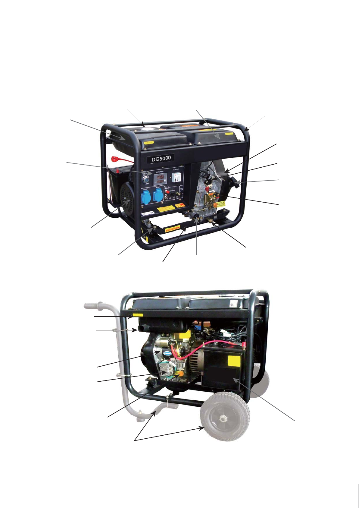
1-1 Generator Component Identification
Open Type: D*
FUEL TANK
CONTROL PANEL
ALTERNATOR
RUBBER ABSORBER
FUEL TANK CAP
BOTTOM FRAME
UP COVER
FRAME
DIESEL ENGINE
INJECTION PUMP
RECOIL STARTER
SPEED GOVERNOR
COCK OF OIL DRANING
OIL PUMP
AIR CLEANER
MUFFLER
START MOTOR
BATTERY CHARGER
OIL DIPSTICK
BATTERY
PUSH WHEEL KIT
1
Changzhou ITC Power Equipment Manufacturing Co.,Ltd.Changzhou ITC Power Equipment Manufacturing Co.,Ltd.

Changzhou ITC Power Equipment Manufacturing Co.,Ltd.
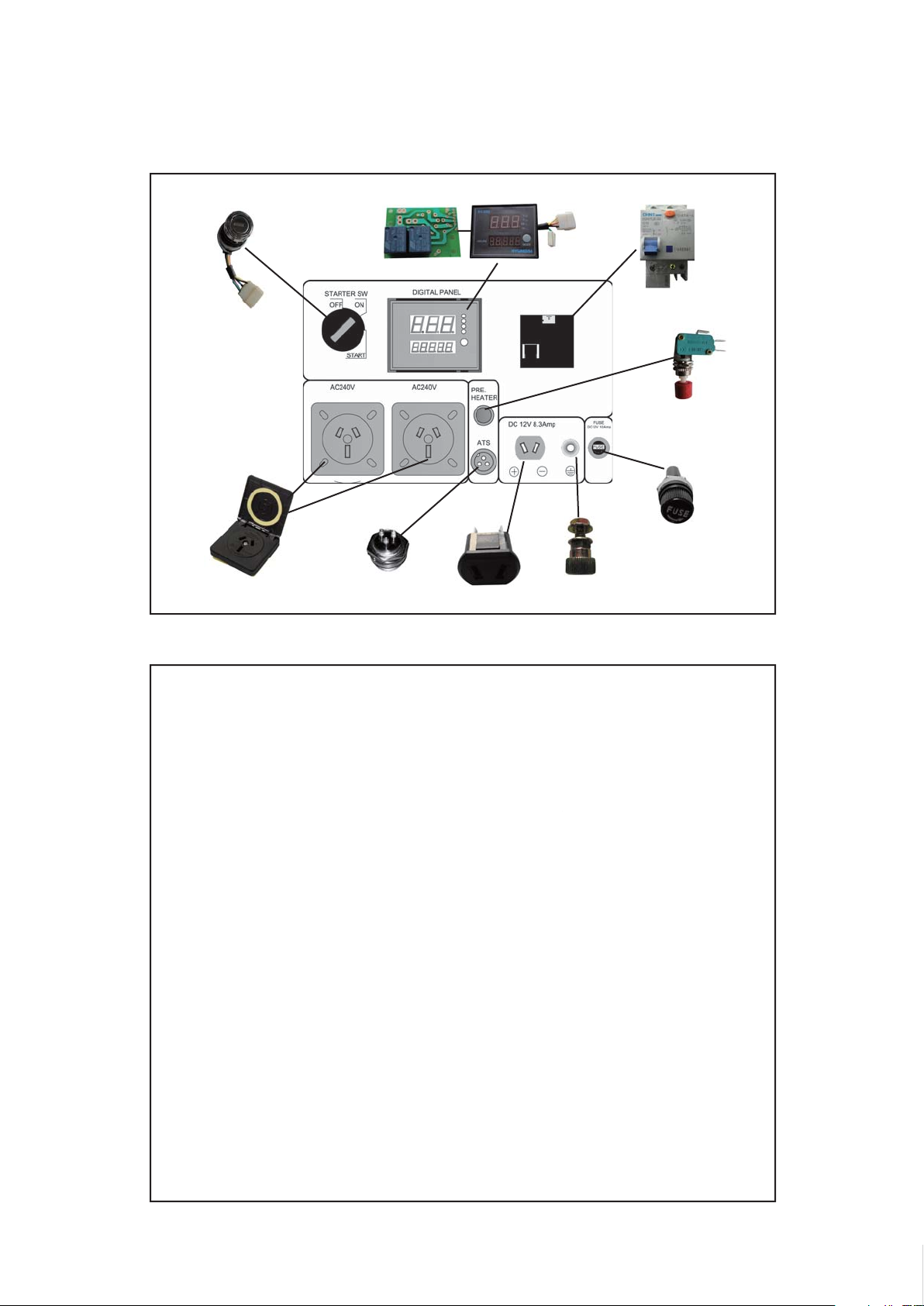
1-2 CONTROL PANEL
ELECTRIC START KEY
SOCKET
PCB
ATS SIGNAL SOCKET
LED4 DISPLAY
12V DC SOCKET
LEAKAGE BREAKER
PRE-HEATER BUTTON
12V DC FUSE
GROUND TERMINAL
Changzhou ITC Power Equipment Manufacturing Co.,Ltd.

LDG4600E Specifi cations
Frequency (HZ) 50 Cooling system Forced Air cooled
Starting Watts 4600 Lubricaton system Forced lubrication
Running Watts 4200 Operation capacity (hr) >12 hrs (25% load)
Voltage (V)
DC output (VA) 12 / 8.3 Net Weight (kgs) 95
Pole Numbers 2 Noise Level dBa@7m 84-89
Insulation B Certifi cation
Engine Model 182FE Start System Electric Key
Engine Type
Displacement (cc) 296 Lube oil capacity (L) 1.1 (SAE10x30)
Engine Speed (RPM) 3000
Low oil pressure alarm
system
1 x 110v 32 Amp / 1 x 240v
32 Amp
Single cyinder, vertical, 4
stroke air cooled direct
injection diesel engine.
Included
Dimension L*W*H (mm) 720 x 492 x 650
ISO9001-2000, GS,
TUV & CE
Fuel tank capacity (L) 15

1-5 Maintenance Standard
Diesel Engine
Parts Item Standard Service limit
POWER PRODUCTS
Diesel
Engine
Maximum Speed (No Load)
Cylinder Compression
Cylinder Sleeve I.D
Cylinder Head
Cover
Warpage -- 0.10mm
Skirt O.D.
Piston-to-Cylinder Clearance
Piston
Piston Pin Bore I.D.
Piston Pin O.D
Piston Pin-to-Piston Pin Bore Clearance
Ring Side Clearance:
Piston Rings
Ring Enc Gap:
Ring Width
Small End I.D
Second
Second
Second
3150~3180rpm
≥1.17Mpa(1400rpm)
86.0mm
+0.035
0
85.94mm
0.015-0.05mm
Ø23mm Ø23.05mm
-.0002
-0.008
18.0mm
0.002-0.014mm
0.015-0.045mm
--
0.2-0.4mm
0.15-0.35mm
1.5mm
2.5mm
18.002mm
--
--
86.185mm
85.80mm
0.12mm
17.954mm
0.06mm
0.15mm
--
1.0mm
1.0mm
1.37mm
2.37mm
18.07mm
Connecting
Rod
Big End I.D
Big Oil Clearance
Big End Side Clearance
30.02mm
0.040-0.063mm
0.1-0.7mm
30.066mm
0.12mm
1.1mm
Crankshaft Crankshaft pin O.D 29.98mm 29.92mm
Valve
Valve Clearance IN
EX
Stem O.D IN
EX
Guide I.D
Stem Clearance IN
EX
Seat Width
Spring Free Length
0.15±0.02mm
0.20±0.02mm
5.48mm
5.44mm
5.50mm
0.02-0.044mm
0.06-0.087mm
0.8mm
34mm
--
--
5.318mm
5.275mm
5.572mm
0.1mm
0.12mm
2.0mm
32.5mm
7
Changzhou ITC Power Equipment Manufacturing Co.,Ltd.Changzhou ITC Power Equipment Manufacturing Co.,Ltd.Changzhou ITC Power Equipment Manufacturing Co.,Ltd.Changzhou ITC Power Equipment Manufacturing Co.,Ltd.Changzhou ITC Power Equipment Manufacturing Co.,Ltd.

POWER PRODUCTS
Cam Height IN
Camshaft
Crankcase
Cover
Carburetor
Spark Plug Gap 0.7-0.8mm -Spark Plug
Cap
Ignition Coil
Cam Height EX
Journal O.D
Camshaft Bracket I.D 14.0mm 14.048mm
Main Jet
Float Height
Pilot Screw Opening
Resistance 5kΩ --
Resistance Primary Coil
Secondary Coil
Air gap
27.7mm
27.75mm
13.984mm
#68
13.7±1.5mm
2-1/8 turns
0.8-1.0Ω
5.9-7.1kΩ
0.4-0.6mm
y Generator
27.45mm
27.50mm
13.916mm
--
--
--
--
--
--
Parts Item Standard Service limit
Stator Winding 1.8±10%Ω at 20℃ --
Stator Winding Resistance
Stator Auxiliary Winding 3.5±10%Ω at 20℃ --
Rotor Excitation
Winding
Carbon Brush Carbon Brush Length 10mm 6mm
Resistance Excitation Winding 51.3±10%Ω at 20℃ --
8
Changzhou ITC Power Equipment Manufacturing Co.,Ltd.Changzhou ITC Power Equipment Manufacturing Co.,Ltd.Changzhou ITC Power Equipment Manufacturing Co.,Ltd.Changzhou ITC Power Equipment Manufacturing Co.,Ltd.Changzhou ITC Power Equipment Manufacturing Co.,Ltd.
POWER PRODUCTS
2. Periodic Maintenance
2.1 Service Intervals
Good maintenance is essential for safe, economical, and trouble-free operation. It will also help reduce air
pollution.
Exhaust gas contains poisonous carbon monoxide. Shut off the engine before
perform any maintenance. If the engine must be run, make sure the area is well
WARNING
ventilated.
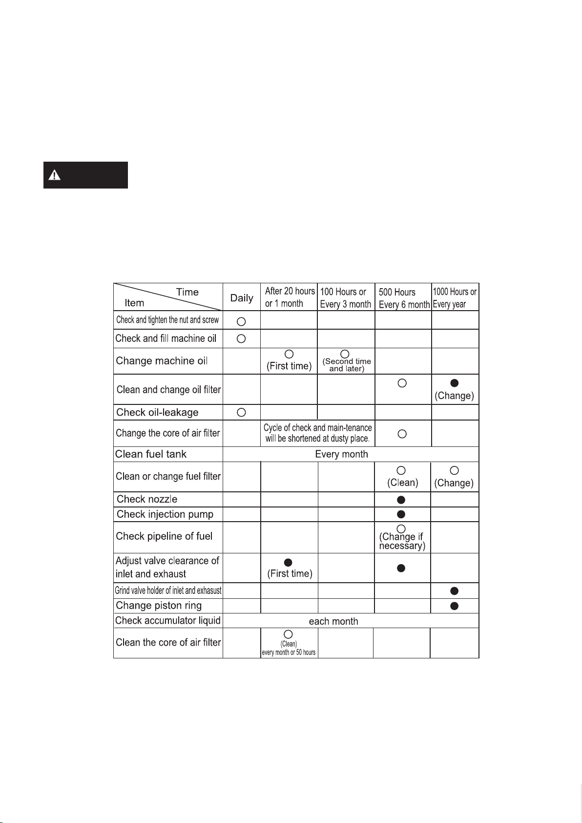
Periodic maintenance and adjustment is necessary to keep the generator in good operating condition.
Perform the service and inspection at the intervals shown in the Maintenance schedule below:
(1) Service more frequently when used in dusty areas.
(2) These items should be serviced by an authorized generator dealer.
(3) When more often use, only servicing according to above correct intervals can insure the generator set
long-term use.
9
Changzhou ITC Power Equipment Manufacturing Co.,Ltd.Changzhou ITC Power Equipment Manufacturing Co.,Ltd.Changzhou ITC Power Equipment Manufacturing Co.,Ltd.Changzhou ITC Power Equipment Manufacturing Co.,Ltd.Changzhou ITC Power Equipment Manufacturing Co.,Ltd.
POWER PRODUCTS
2-2 Routine Maintenance Procedures
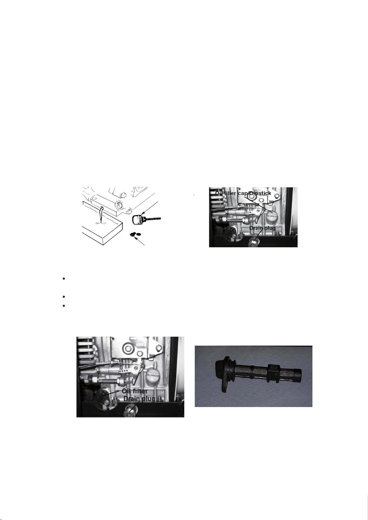
2.2.1 Oil Change
Drain the used oil while the engine is warm. Warm oil drains quickly and completely.
1. Place a suitable container below the engine to catch the used oil, and then remove
the filler cap/dipstick and the drain plug.
2. Allow the used oil to drain completely, and then reinstall the drain plug, and tighten
it securely.
3. With the engine in a level position, fill to the outer edge of the oil filler hole with the
recommended oil.
DIPSTICK
DRAIN BOLT
2.2.2 Oil Filter Service
Remove the bolt that secures the filter and carefully pull the assembly toward
you.
The filter may be immersed in solvent then blown dry with compressed air.
Replace the filter at the scheduled service interval or anytime the screen is
damaged or all deposits cannot be removed.
10
Changzhou ITC Power Equipment Manufacturing Co.,Ltd.Changzhou ITC Power Equipment Manufacturing Co.,Ltd.Changzhou ITC Power Equipment Manufacturing Co.,Ltd.Changzhou ITC Power Equipment Manufacturing Co.,Ltd.Changzhou ITC Power Equipment Manufacturing Co.,Ltd.

2.2.3 Air Filter Service
Remove the air cleaner cover and inspect the filter. Clean or replace dirty filter elements.
Always replace damaged filter elemen ts.
POWER PRODUCTS
2.2.4 Fuel Filter Service
1. Drain out the fuel from the fuel tank. Turn the screw in the drain plug counter
clockwise until fuel flows. Use a suitable container to catch the fuel.
2. Remove the three screws securing the fuel cock assembly and remove the filter
from the housing.
FUEL TANK
DRAIN PLUG
FUEL COCK
FUEL FILTER
ASSEMBLY
11
Changzhou ITC Power Equipment Manufacturing Co.,Ltd.Changzhou ITC Power Equipment Manufacturing Co.,Ltd.Changzhou ITC Power Equipment Manufacturing Co.,Ltd.Changzhou ITC Power Equipment Manufacturing Co.,Ltd.Changzhou ITC Power Equipment Manufacturing Co.,Ltd.
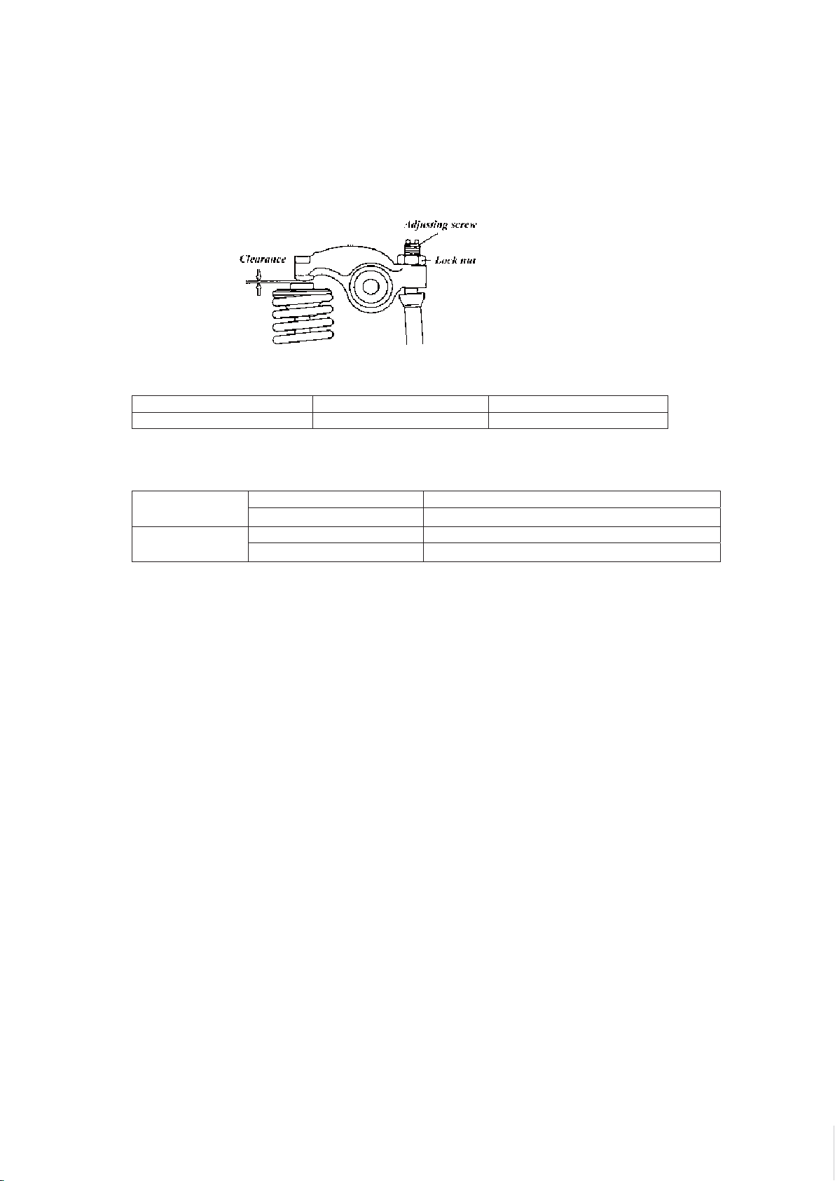
2.2.5 Adjust the va lve clearance
(1) The clearance must be adjusted when the engine is cold.
(2) Valve timing
Intake
Exhaust
Close
Close
POWER PRODUCTS
timiL ecnanetniaM dradnatS
-- mm 51. ecnaraelc tsuahxE/ekatnI
CDT erofeb °41 nepO
50°after BDC
CDB erofeb °45 nepO
10°after TDC
12
Changzhou ITC Power Equipment Manufacturing Co.,Ltd.Changzhou ITC Power Equipment Manufacturing Co.,Ltd.Changzhou ITC Power Equipment Manufacturing Co.,Ltd.Changzhou ITC Power Equipment Manufacturing Co.,Ltd.Changzhou ITC Power Equipment Manufacturing Co.,Ltd.
3. Engine disassembly and reassembly
3.1 Disassembly
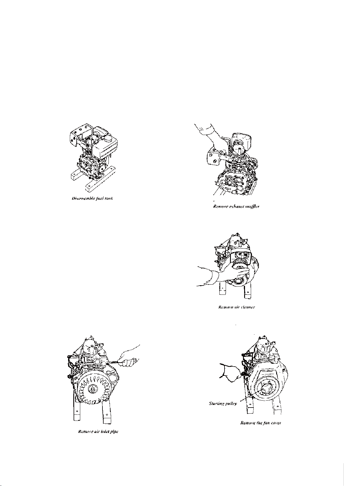
3.1.1 Fuel tank
1. Release the joint between the fuel line and fuel tank.
2. Release the hose clamp of the fuel line on the pump side.
3. Remove the tank.
POWER PRODUCTS
3.1.2 Exhaust Muffler
1. Remove the flange bolt
2. Remove the set bolt
3. Discard the muffler gasket. Do not reuse.
3.1.3 Air cleaner
(1). Disassemble the air cleaner cover.
(2). Pull out the element.
(3). Disassemble the air cleaner bottom case.
3.1.4 Recoil starter unit
(do not disassemble)
3.1.5 Disassemble the fan cover
Unbolt and remove the fan cover.
4.1.6 Starter pulley
Unbolt and remove
13
Changzhou ITC Power Equipment Manufacturing Co.,Ltd.Changzhou ITC Power Equipment Manufacturing Co.,Ltd.Changzhou ITC Power Equipment Manufacturing Co.,Ltd.Changzhou ITC Power Equipment Manufacturing Co.,Ltd.Changzhou ITC Power Equipment Manufacturing Co.,Ltd.
3.1.7 Air inlet pipe
3.1.8 Remove electric starter motor
3.1.9 Remove cylinder head cover
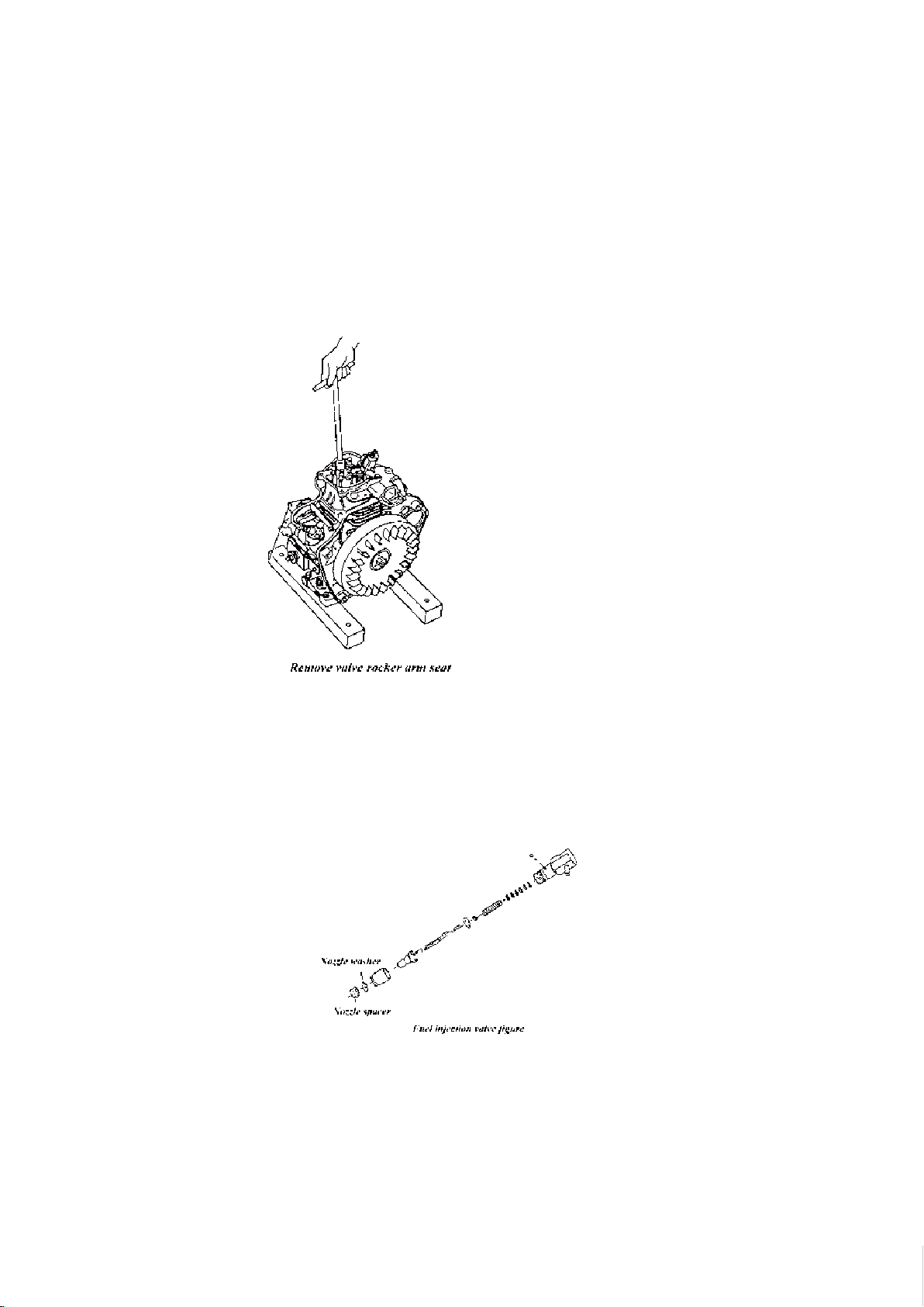
3.1.10 Valve rocker arm seat
POWER PRODUCTS
3.1.11 Push rods
3.1.12 Fuel injector
(1) Remove the high-pressure fuel line.
(2) Remove fuel injector.
(3) Be careful not to damage the nozzle washer and spacer.
14
Changzhou ITC Power Equipment Manufacturing Co.,Ltd.Changzhou ITC Power Equipment Manufacturing Co.,Ltd.Changzhou ITC Power Equipment Manufacturing Co.,Ltd.Changzhou ITC Power Equipment Manufacturing Co.,Ltd.Changzhou ITC Power Equipment Manufacturing Co.,Ltd.

3.1.7 Air inlet pipe
3.1.8 Remove electric starter motor
3.1.9 Remove cylinder head cover
3.1.10 Valve rocker arm seat
POWER PRODUCTS
3.1.11 Push rods
3.1.12 Fuel injector
(1) Remove the high-pressure fuel line.
(2) Remove fuel injector.
(3) Be careful not to damage the nozzle washer and spacer.
15
Changzhou ITC Power Equipment Manufacturing Co.,Ltd.Changzhou ITC Power Equipment Manufacturing Co.,Ltd.Changzhou ITC Power Equipment Manufacturing Co.,Ltd.Changzhou ITC Power Equipment Manufacturing Co.,Ltd.Changzhou ITC Power Equipment Manufacturing Co.,Ltd.
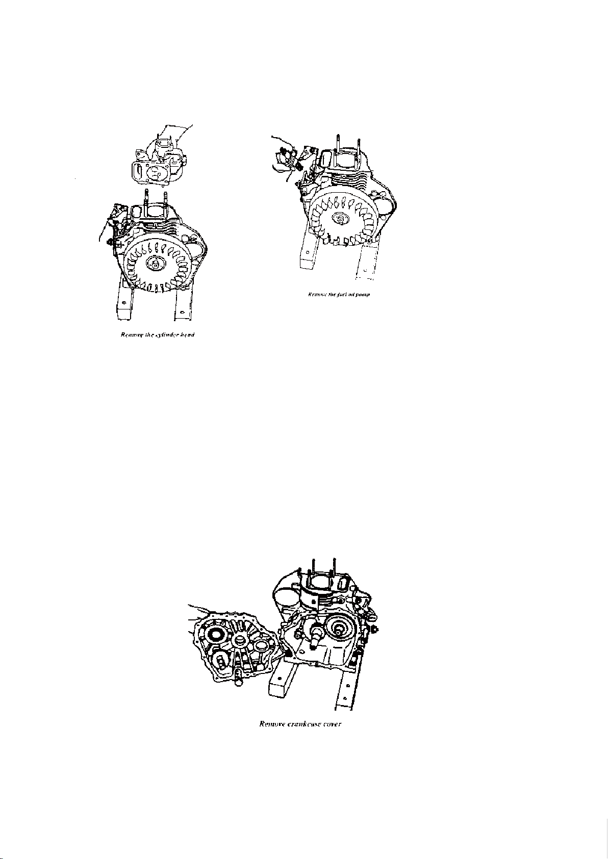
3.1.13 Remove the cylinder head
POWER PRODUCTS
3.1.14 Remove the injection pump
(1) Remove the pump together with the base.
(2) Ensure the hooking part of control lever is at the meshing position before
disassembling.
(3) Pull out the flat tappet remaining inside the housing
3.1.15 Crankcase cover
(1) Remove the engine oil injection pump cover.
(2) Remove the engine oil filter cover.
(3). Remove crankcase cover.
16
Changzhou ITC Power Equipment Manufacturing Co.,Ltd.Changzhou ITC Power Equipment Manufacturing Co.,Ltd.Changzhou ITC Power Equipment Manufacturing Co.,Ltd.Changzhou ITC Power Equipment Manufacturing Co.,Ltd.Changzhou ITC Power Equipment Manufacturing Co.,Ltd.
 Loading...