

Page 1

( E
EV 30i
INVERTER GENERATOR
( !
......:6
Page 2

MANUAL
Inverter Generator
EV 30i
Page 3

PREFACE
Thank you for purchasing our generators.
This manual covers operation and maintenance of the EV30i generator.
All information in this publication is based on the latest product information
Available at the time of approval for printing.
We reserve the right to make changes at any time without notice and without
incurring any obligation.
No part of this publication may be reproduced without written permission.
This manual should be considered a permanent part of the generator and should
remain with it if it is resold.
Pay special attention to statements preceded by the following words;
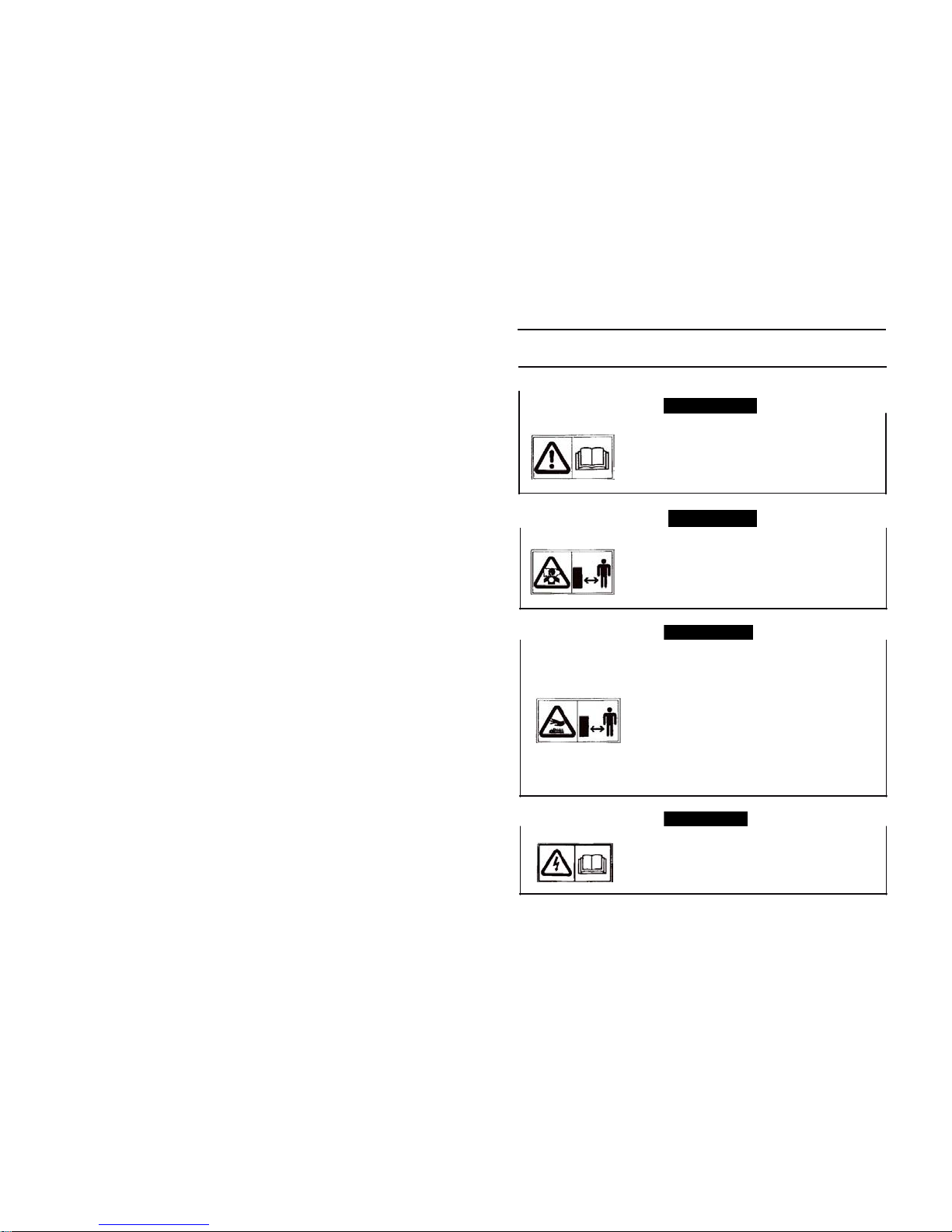
Failure to properly follow these precautions can result in
property damage, serious injury or DEATH!
Read all labels and the owner's manual before operating
this generator.
Operate only in well ventilated areas. Exhaust gas
Contains poisonous carbon monoxide, and can be
deadly. Always stop engine before refuelling. W ait 5
minutes before restarting.
Check for spilled fuel or leaks. Clean and/or repair before
use.
Keep any sources of ignition away from fuel tank, at all
times.
Indicates a strong possibility of severe personal inj ury or
death if instructions are not followed.
Indicates a possibility of personal injury or equipment
damage if instructions are not followed.
NOTE: Gives helpful information.
If a problem should arise, or if you have any questions about the generator,
consult an authorized dealer.
Our generators are designed to give safe and dependable
service if operated according to instructions. Read and
understand the Owner's Manual before operating the
Failure to do so could result in personal injury or
equipment damage.
Page 4

CONTENTS
1.SAFETY INSTRUCTIONS - - - - - - - - - - - - - - - - - - - - - - - - - - - - -
· 1
2.
SAFETY LABEL LOCA
TIONS --------------------------------------3
3.
PRE-OPERATION CHECK --------------------------------------- 5
4.STAR TING THE ENGINE - - - - - - - - - - - - - - - - - - - - - - - - - - - - - · 8
5.GENERAT OR USE - - - - - - - - - - - - - - - - - - - - - - - - - - - - - - - - - · 11
6.STOPPING THE ENGINE - - - - - - - - - - - - - - - - - - - - - - - - - - - - - · 14
7.MAINTENANCE -------------------------------------------------- 15
8.
TRANSPORTI NG/STORAGE --------------------------------- 21
9.
TROUBLESHOOTI NG ------------------------------------------ 22
1O.SPECI FICATIONS ------------------------------------------ 24
11.
WIRING DIAGRAM ------------------------------------------ 25
12.
WHEEL KIT -----------------------------------------------------------26
13. APPENDIX ------------------------------------------------- 27
Page 5
•
Exhaust gas contains poisonous carbon monoxide.
Never run the generator in an enclosed area.
Be sure to provide adequate ventilation.
When installed in ventilated protection are to be
observed.
•The muffler becom es very hot d uring operation and
remai ns hot for a w hile after stopping the engine.
Be caref ul not to touch the muffler while it is hot.
Let the engine cool before storing the generator
indoors.
The engine exhaust system will be heated during operation and remain hot immediately after stopping the
engine.
To prevent scalding, pay attention to the warning
marks attached to the generator.
•Never connect a cable other than the special cable
for parallel operation to the parallel operation socket.
Electric shocks can result if this instruction is not
followed.
1.
SAFETY INSTRUCTI ONS
A.WARNING
-1-
A.CAUTION
A.WARNING
A.WARNING
•Our g enerators are d esigned to giv e safe and d ependable service if operated according to instructions.
Read and und ersta nd the Ow ner's Manual bef ore operating the generat or. Fa ilure to do so could res ult in
personal injury or equipment damage.
Page 6

AWARNING
•
Gasoline is extremely flammable and explosive under certain conditions.
Refuel in a well ventilated area with the engine stopped.
•
Keep away from cigarette, smoke and sparks when refueling the generator.
Always refuel in a well-ventilated location.
•
Wipe up spilled gasoline at once.
AWARNING
•
Connections for standby power to a building's electr-
ical system must be made by a qualified e lectrician
and must comply with all applicable laws and electri
cal codes. Improper connections can allow electrical
current from the generator to back feed into the utility
lines.Such back feed may electrocute utility company
workers or others who contact the lines during a
power outage, and when utility power is restored,
the generator may explode, burn, or cause fires in
the buildings electrical system.
AWARNING
•Always make a pre-operation inspection before you start the engine. You
may prevent an accident or equipment damage.
•
Place the generator at le ast 1m(3ft) away from buildings or other equip
ment during operation.
•
Operate the generator on a level surface.
If the generator is tile d, fuel sp illage ma y result.
•Know how to stop the generator quickly and understand operation of all t he
controls. Never permit anyone to operate the generator without proper
instrucions.
•
Keep children and pets away from the generator when it is in operation.
•
Keep away from rotating parts while the generator is running.
•The generator is a potential source of electrical shocks when misused; do
not operate wit h wet hands.
•Do
not operate the generator in rain or snow and do not let it get wet.
To ensure safe operation--
2.
SAFETY LABEL LOCATIONS
2.1 Outside view
-2-
-3-
Maintenanc e
cover
Control panel
Air intake hole
Air c leaner
Fuel lev el ind icator
Start grip
Air Exhaust h ole
Fig1. Outside view
Page 7

A.NOTE
•When
high electrical load appliances are connected simultaneously , turn
the smart throttle switch to the OFF position to reduce voltage changes.
•
Smart t hrottle system does not operate sufficiently if the electrical
appliance equires the much electric power.
Lower limit
2.2 Control panel
SMART thrott le switc h
3.
PRE-OPERATI ON CHECK
Fig 2. Control panel
Be sure to check the generator on a level surface with the engine stopped.
3.1
Check the engine oil level.
SAE Viscosity Grades
2.3 SMART throttle
Engine speed is kept at idle automatically when the electrical appliance is
disconnected and it will return to the proper speed by the electrical load when
electrical a ppliance is connected. This position is recommended to minimize the
"
.,
"
100 'F
Fuel consumption while in
operation
-20-
-10
10 20 30 40 'C
Ambient Temperature
Open t he oil maintenance cover. Remove the oil filler cap, and wipe the
dipstick with a clean rag. Check the oil level by inserting the dipstick in the filler
hole without screwing it in. If the o il level is below the end of the dipstick, refill
with recommended oil up to the top of the oil filler neck.
OFF:
SMART throttle system does not operate. Engine speed is kept over rated speed.
-4-
A.CAUTION
•Using nondetergent oil or 2-stroke engine oil could shorten the engine's
service life.
•Use high-detergent , premium quality 4-stroke engine oil, certified to meet
or exceed U.S. autom obile ma nufact urer's require ment s for API Service
Classification SG,SF.
•
Select the appropriate viscosity for the average temperature in your area
>OW
20W
Single
viscosity
20
30
'"
Multi-
viscosity
'"
Page 8

Fig.3
5
-
Page 9

.A.WARNING
•
Gasoline is extremely flammable and is explosive under certain conditions.
•Refuel in a we ll-ventilated area with the engine stopped. Do not smoke or
allow flame or sparks in the area where the engine is refueled or where
gasoline is stored.
•Do
not overfill the f uel tank (there should be no fuel in the filler neck). After
refueling, make sure the fuel filler cap is closed properly and securely.
•Be
careful not to spill f uel when refueling. Spilled fuel or fuel vapor may
ignite.
If any fuel is spilled, make sure the area is dry before starting the engine.
•Avoid repeated or prolonged contact with skin or breathing of vapor. KEEP
OUT OF REACH OF CHILDREN.
Oil
surface
Oil
surface
Strainer
•Fuel system damage or engine performance problems resulting from the
use of fuels that contain alco hol is not covered under the warranty. We
cannot endorse the use of fuels containin g methanol since evidence of
their suitabilit y is as yet incomplete.
•
Before buying fuel from an unfamiliar station, try to find out if the fuel
contains alcohol, if it does, confirm the type and percentage of alcohol
used. If you notice any undersirable operating symptoms while using a
gasoline t hat contains alcohol, switch to gasoline that you k now does not
contain alcohol.
A.NOTE
3.2 Check the fuel level
Use automotive gasoline (Unleaded is preferred to minimize combus
tion
chamber
deposits).
If the fuel level is low, refill to the shoulder of the fuel strainer, see fig. 4.
Never use an oil/gasoline mixture or dirty gasoline.
Avoid getting dirt, dust or water in the fuel tank.
After refuelling, tighten the fuel filler cap securely.
Gasoline’s containing alcohol
If you decide to use a gasoline containing alcohol (gasohol), be sure its octane
rating is at least as high as that recommended by us. There are two types of
"gasohol": one containing ethanol, and the other containing methanol. Do not use
gasohol that contains more than 10% ethanol. Do not use gasoline containing
methanol (methyl or wood alcohol) that does not also contain solvents and
corrosion inhibitors for methanol. Never use gasoline containing more than 5%
methanol, even if it has solevents and corrosion inhibitors.
Fuel tank capacity: 1 3L
Fig.4
-6-
3.3 Check the air cle aner
Check the air cleaner elements to be sure they are clean and in good condition.
Open the left side maintenance cover. Remove the air cleaner cover, remove the
paper element from the air cleaner cover, and check the both elements, clean or
replace the element(s) if necessary, see fig.5.
Fig. 5
-7-
.A.CAUTION
•Never run the engine without the air cleaner. Rapid engine wear will
result from contaminants, such as dust and dirt, being drawn through the
carburetor, into the engine.
.A.CAUTION
•Running the engine w ith insufficient oil can cause serious engine damage.
•The Low O il Alarm System will automatically stop the engine before the oil
level falls below the safe limit. However, to avoid the inconvenience of an
unexpected shutdown, it is still advisable to visually inspect the oil level
regularly.
Page 10

A
CAUTION
•When starting the generator after adding fuel for the first time, after
longterm storage, or after running out of fuel, tum the fuel valve lever to
the "ON" position, then wait for 10 to 20 seconds before starting the
Fuel valve lever
Engine switch
Starter grip
4.
STARTING THE ENGINE
4.1
Turn the fuel valve lever to the ON position, see fig.6.
4.3 Insert the engine key, and turn the engi ne s witch to ON posi tion.
Fig.8
4.4(a) Turn the engine s witch to the START until the engine has started,
see Fig.9(a).
4.4(b) Pull the starter grip lightly until resistance is felt, then pull the
starter grip briskly toward the arrow as sho wn below, see Fig. 9(b).
Fig.6
4.2 Pull the choke knob out to the CLOSED positi on
Do not use the choke when the engine is warm or the air temperature is high, see
fig.7.
Fig.9(a)
Fig.9(b)
Fig.7
-8-
-9-
A.CAUTION
•Do
not allow the starter grip to snap back. Return it slowly by hand.
•Do not let the starter rope rub against the generator body or the rope will
wear out prematurely.
Page 11

.ACAUTION
•
Limit operation requiring maximum power to 30 minutes.
For continuous operation do not exceed the rated power.
In either case, the total wattage of all appliances connected must be
considered.
•Do
not exceed the current limit specif ied for any one receptacle.
•Do
not connect the generator to a household circuit. This could cause the
damage to the generator or to electrical appliances in the house.
•Do
not modify or use the generator for other p urposes than it si intended for
Also observe the following when using the generator.
.Do not connect generators in parallel.
.Do not connect an extension to the exhaust pipe.
•
When an extension cable is required, be sure to use tough rubber sheathed
flexible cable.
•Limit length of extension cables; 60 m for cables if 1.5mm
2
and 1OOm for
cables of 2.5 mm
2
•
•
Keep the generator away from other electric cables or wires such as com-
4.5 Push th e choke k no b to the OPEN p o s i t i o n as the engine warms
Up, see page 10.
5. GENERATOR USE
High altitude operation
Fig.10
At high altitude, the standard carburettor air-fuel mixture will be excessively rich
Performance will decrease, and fuel consumption will increase.
High altitude performance can be improved by installing a smaller diameter main
fuel jet in the carburettor and readjusting the pilot screws. If you always operate the
generator at altitudes higher than 1,500 m (5,000 feet) a bove sea level, have
your authorized dealer perform these carburettor modifications.
Even w ith suitable carburettor jetting, engine horsepower will decrease
approximately 3.5% for each 305 m (1.000 feet) increase in altitude. The effect of
altitude on the horsepower will be greater than this if no carburettor modification is
made.
-10-
-11-
.ACAUTION
•Operation of the generator at an altitude lower than the carburetor is jetted
for may result in reduced performance, overheating, and serious engine
damage caused by an excessively lean air/fuel mixture.
.A.WARNING
•To
prevent electrical shock from faulty appliances, t he generator should be
grounded. Connect a length of heavy w ire between the generator's ground
terminal and an external ground source.
•Connections f or standby power to a building's electrical system must be
made by a qualified electrician and must comply with all applicable laws
and electrical codes. Improper connections can allow electrical current from
the generator to backfeed into the utility lines. Such backfeed may
electrocute utility company workers or others who contact the lines during a
power outage, and when utility power is restored, the generator may explode,
burn, or cause fires in the building's electrical system.
A' --
l
Ground
l
terminal .
Page 12

b tt
t
.
I
A.WARNING
•
To prevent the possibility of creating spark near the battery, connect charg-
ing c able f irst to th e generator, then to the battery. Disconnect cable first at
the battery.
•Before connecting chargin g cable to a battery that is i nstalled in a vehicle,
disconn ect the vehicles gr ounded battery cable. Reco nnect the vehicle's
ground ed battery cable after the ch arging cables are removed. This pr oced
dure will prevent the possibility of a short circuit and sparks if you m ake ace
idental contact between a battery terminal and the vehicl e's frame or body.
A.CAUTION
•Do
not attem pt to start an automobile engine with the generator still conn-
ected to batter. The generator may be damaged.
•Connect the positive battery terminal to the positive charging cord. Do not
reverse t he chargi ng cabl es, or seri ous dam age to the generator and/or
battery may oc cur.
A.WARNING
•The battery gives off explosive gases; keep sparks, flames and cigarettes
away. Provide adequat e ventil ation when charging.
•The
battery contains sulfuric acid {electrol yte). Contact with ski n or eyes
may cause sever e b urns. W ear protective clothi ng and a face shi eld.
A.
If electrolyte gets on your skin, flush with water.
B.
lf electrolyte gets in your eyes, flush with water for at l east 15 mi nutes
and call a physici an.
•Electrolyte is poisonous.
A. If swallowed, drink large qua ntities of water or milk and follow with milk of
magneci a or veg etable oil and call a physici an.
•
Keep out of r each of children.
5.1 AC applications
1.
Start the engine and make sure the green output indicator lig ht comes on.
2.
Confirm th at the appliance to be used is switched off and plug in th e appliance.
5.3
DC application
The DC recept acle m ay be us ed for ch arging 12 volt automotive-typ e batteries only.
Output voltage is 15-30V when current recept acle on no load. DC output will vary
according to the po sition of the Sm art throttl e switc h. Wh en the Sm art throttle swit ch
is turned to the ON position and the AC output is n ot used, the DC current will be
about one-third of the rated current.
DC current:
I
OFF
ON
{do not use the AC output)
EV30i
8.3A
approximately 2.BA
•
Substanti al overloading that continuo usly lights the red
overload indicator light may dam age the gen erator.
Marginal overloading t hat temp orarily lights the
overload indicator may short en the servi ce life of the
generato r.
•
Be sure that all appliances are in good working order
before co nnecting them to the generator.
If an
appliance begins to op erate a bnormall y, becom es
sluggish, or stops s uddenly, turn off the generator
engine s witch immediately. Disconnect the appliance
and examin e it for signs of malf unction.
1.Conn ect the c harging cable to the DC r eceptacl e of the generator and then to t he
5.2
Output and Overload Indicators
The green output i ndicator light will remai n ON during n ormal op erating c onditions. If
the generator is overloaded or if there is a short in the connected appliance the
output indicat or will go OFF and the overl oad i ndicator will go ON and curr ent to the
connect ed appliance will be shut off.
Stop th e engine if the overload i ndicator light comes ON and in vestigate the
overload source. The engine will co ntinue to r un even t hough it is not pr oducing any
AC pow er. The engine must be stopped and then the gen erator restarted to resume
normal operation.
Check the engine oil level if the r ed oil alarming i ndicator comes ON.
A
NOTE
A
NOTE
•Before connecting an appliance to the generator, check
that it is i n good ord er, and t hat its electrical rating do es
not exceed that of the generator.
Then c onnec t the po wer cord of the appliance, and
start the engine.
•
When an electric motor is started, both the overloa d
indicator light and the output indicator light may go on
simulta neously. This is normal if the overload indicator
light goes off after about four seconds. If the overload
indicator lig ht stays o n, consult your dealer.
-12-
-13-
CAUTION
A
Page 13

2.
Start the engine
•
The DC receptacle may be used while the AC power is in use.
•
An
overloaded DC circuit will trip the DC circuit protector (push button comes
out). If this happens, wait a few minutes before pushing in the circuit
protector to resume oper ation.
7. MAINTENANCE
The purpose of the maintenance and adjustment schedule is to keep the
generator in the best opera ting condition.
Mai1lenanoe
Schedule
6.STOPPING THE ENGINE
To stop the engine in an emergency tum the engines switch
OFF. In normal use:
1.
Switch off the connected equipment and pull the inserted plug.
2.
Tum off t he engine switch.
3.
Tum the fuel val ve lever to the OFF position.
NOTE: (1) Log hours of oper ation to determine proper maintena nce.
(2) Servi ce more frequently when used in dusty areas.
(3)
These items shoul d be serviced by an authorized dealer, unless the
owner has t he proper tools and is m echani cally proficient. See th e
Shop Manual.
AWARNING
•
Shut off the engine before performing an y maintenance. If the engine must
be run, make sure the area is well ventilated. The exhaust contains poisonous carb on monoxide gas.
•
Use genuine our parts or the equivalent. The use
of
replacement parts
which are not
of
equivalent qu ality may damage the generator.
REGULA R SERVICE PE-
RIOD (1) Perform at every
indicated month or operating
hour interval,whichever
oo-
cursfirst
EACH
USE
FIRST
MONTH
OR
20 HRS
EVERY3
MONTHS
OR
50 HRS
EVERY 6
MONTHS
OR
100HRS
EVERY
YEAR
OR
300HRS
ITEM
Engine oil
Check
0
Change
0
0
Air deaner
Check
0
Clean
0
(2)
Spark plug
Clean-adjust
0
Sparkarrester
Clean
0
Fuelsedimentcup
Clean
0
alve dearanc:e
Check-adjust
Q
C3)
Fuel tank
and
straine
Clean
0
(3)
Fuelline
Check
Every 2 y ears (Replace if necessary)(3)
·
Page 14

7.2
Changing oil
Drain the oil while the engine is still warm to assure rapid and complete draining.
Fig.13
1. Open the left side maintenance cover.
2.
Take out the oil outlet plug.
3.
Remove the drain bolt, and drain the oil. Retighten the bolt
securely. 4. Refill with the recommended oil and check the level.
5. Close the left side maintenance cover.
Engine oil capacity 0.55L
1.
Revolve the left side cover knob; open the left side maintenance cover.
2.
Unsnap the clips, remove the air cleaner cover.
3.
Foam element:
•
Remove the foam element from the air cleaner cover.
•Wash the foam element in a solution of household detergent and warm water,
then rinse thoroughly, or wash in non-flammable or high flashpoint solvent.
AL-
low the foam element to dry thoroughly.
•Soak the foam element in clean engine oil and squeeze out the excess oil. The
engine will smoke during initial startup if too much oil left in the foam element.
• Reinstall the foam element to the air cleaner cover.
4.
Paper element:
If
the paper element is dirty, replace it with a new one. Do not
clean the paper element.
5.
Reinstall the air cleaner cover.
6.
Close and latch the left side maintenance cover.
A
NOTE
•Please dispose of used motor oil in a manner that is compatible with the
environment. We suggest you take it in a sealed container to your local service
station for reclamation. Do not throw it in the trash or pour it on the
Round.
7
.3
Air cleaner service
A dirty air cleaner will restrict air flow to the carburettor to prevent
carburettor malfunction, service the air cleaner regularly. Service more frequently
when operating the generator in extremely dusty areas.
-16-
-17-
•
Never run the generator without the air cleaner.Rapid engine wear may result
OH drain bolt
Oildispstick
Page 15

Spark plug lover
Plug gap
0.5-0.75mm
(0.02-0.03in)
7.5
Spark plug service
Recomm ended spark plug: WR7DC
To ensure pr oper eng ine operation, the spark plug must be properly gap ped and
free of deposits.
1.
Open th e left side maint enance cover.
2.
Remov e the spark plug ca p.
3.
Use the wrench to remov e the spark plug.
4.
Clean any dirt from ar ound the s park plug ba se.
7.
Install the s park plug caref ully, by hand, to avoid cross-threadin g.
8.
After a new spark plug has been seated by hand, it should be tightened 1/2 tum
with a wrench to compr ess its washer.
If a used plug is being rein stalled, it should only require 1/8 to 1/4 turn after bei ng
seated.
9.
Reinstall the spark plu g inspec tion cover and tighten the cover screw.
10.
Close and l atch the l eft side maintenance cover.
Fig.14
5. Visually inspect the spark plug. Discard it if the insulator is crack ed or chipp ed.
Clean the spark plug with a wire brush if it is to be reuse d.
6.
Measure the plug gap with a f eeler gauge.
The g ap sh ould be 0.5-0.7 5mm (0.0 2-0.03in). Correct as necessary by carefully
bending t he si de electrode.
Fig. 15
-18-
-19-
t
A.CAUTION
•The
spark plug mu st be se curely tightened. An improperly tigh tened plug
can bec ome very hot and possibly damage the generator.
•
Never use a spark plug with an improp er heat range.
Page 16

•
The spark arrester must be serviced every 100 hours to maintain its efficiency.
7.6
Spark arreste r mainten ance
Fig. 16
A.WARNING
•
If the generator has been running, the muffler will be very hot. Allow it to
cool before proceeding.
8. TRANSPORTING/STORAGE
8.1 When t ra n s p o r t i ng t h e generator, tum the fuel v a l ve lever O FF and
keep the generator level to prevent fuel spillage. Fuel vapour or spilled fuel may
ignite.
8.2 Before storing the unit for an extended period:
1.Be sure the storage area is free of excessive
humidity and dust.
2.
Drain the
fuel-
a.
Open the left side maintenance cover.
b.
Turn fuel valve leve r to ON and then loosen the
carburettor drain screw. Drain the gasoline from
the
Carburettor and fuel tank and store in a suitable container.
Fig. 17
c.
Tighten the c a r b u r e t t o r screw, close t h e f u e l v a l v e lever a n d
l e f t s i de maintenance cover.
3. Once a month, recharge the battery.
4. Change the engine oil.
5.
Remove the spark plug and pour about a tablespoon of clean engine oil into the
cylinder. Crank the engine several re volutions to distribute the oil, and then
reinstall the spark plug.
6.
Slowly pull the starter grip until resistance is felt. At this point, the piston is
coming up on its compression stroke and both the intake and e xh a us t valves
are c losed.
Storing the engine in this po sition will help to protect it from interna l corrosio n.
1.
Remov e the back cover.
2.
Remove the exhaust tail pipe and spark arrester.
3.
Use a brush to remove carbon deposits from the spark arrester screen.
4.
Reinstall the spark
arrester. 5. Reinstall the upper
•
Inspec t the spark arrester screen f or holes or tears. Replac e
if
necessary.
Page 17

back cover.
-20-
-21-
Page 18

Take the generator to an
authorized dealer.
Take the generator to an
authorized dealer.
•Replace the electrical
appliance or equipment
•Take the electrical appliance or equipment to an
electrical shop
for
repair
A WARNING
•
Be sure there is no spilled
fuel around the spark plug
Spilled fuel may ignite.
9. TROUBLESHOOTING
Appliance does not operate:
Is the output indicator light ON?
When the engine will not start
I s there fuel i n the tank?
iYES
NO
NO
11ol
Refill the fuel tank.
YES
NO
Is the overload
NO
indicator light
ON?
Isthe engine
switch
oo?
Turn the engine switch on.
YES
Is the fuel valve on?
NO
YES
NO
i
YES
Is the enough oil inthe engine?
YES
11o
l
Tum the fuel valve on.
NO
11o l
Add the recommended oil.
Is there a spark from the
Replace the
spark plug?
spark plug.
To check:
1)
Remove the spark plug cap and clean
any dirt from around the spark plug.
2)
Remove the spark plug and install the
No electricity at the DC receptacle:
. 1 s_o_c ci_rc""Tu"i"t_p_ro_te_c_to_r_o_n_?
t---
NO
--•I
Tumthe
DC circui t protector on.
I
Is the fuel reaching the
carburetor?
spark plug in the plug cap.
3)
Set the plug side electrode on the
cylinder head to ground.
4)
Crank the engine, sparks shouldjump
aaoss the gap.
To check:
1)
Tum off the fuel valve and lossen the
drain screw.
2) Fuel should flow from the drain when
the fuel valveIs turned on.
YES
Take the generatorto an
authorized dealer.
Check the electrical appliance or equipment for any
defects.
YES
Take the generator
to an authorized
dealer.
,
,
If the ergine still does not
start.
take
the generator
to
an
authorized dealer.
Page 19

-22- -23-
Page 20

.
.
0
rn rn
10. SPECIFICATIONS
11. WIRING DIAGRAM
DC output
ig1
0
::::J
I
rn
0
'
5j ffi
, r,
--- I
ffi
Engine
rn
a:
&
rn
0
,
.,.
i
s
r
L-o--w--o--il-s-w
---it-cC
h
MA, ---- 0
Trigger winding
!
-
.A.•
\.A.
Ignition coil
ta-
:
;'<:
if)
*:
The declared values shall consider uncertainties due to production variation and
measure ment procedur es.
-24-
Fig.18 EV30i Wiring diagram
-25-
w
()
Model
EV 30i
Rated f requenc y (Hz)
50 60 60
Rated v oltage (V)
230 120
240
Rated current (A)
12.2
23.3
11.7
Rated speed (r pm)
3600
Rated output (kVA)
2.8
Max. ou tput (kVA)
3.0
DC voltage
12V-8.3A
Electr ic circu it b reaker
Without
Phas e num ber
Single phase
Model Type
KG205 GETi
Type
Single cylind er, 4 stroke, vert ical, air-cooled, OHV,gasoline engine
Displ acement (Bor e
x
Strok e)
196ml (68 x 54mm)
Compr ess ion ratio
8.5:1
Rated power [kW (Hp)/(r/min)]
4.0/3600
Igni tion syst em
T. C.
I
Spark plug
WR7 DC
Starting system
Recoil starter, Electric starter
Fuel
Autom otive unleaded gasoli ne
Fuel c onsum ption (g /kW .h)
395
Lube oil
CD grade or SAE 10W-30, 15W-40
Fuel tank capacit y (L)
13
Contin uous running time ( hr) (at rated output)
6
Noise level(zero load- full load) [dB(A)/ 7m]
62-66 *
Overall dimension (LX W X H) [mm(i n)]
EV30i:686 X 425 X 495(27.01 X 16.73 X 19.49)
Dry weigh t [kg(lbs))
EV30i: 60 (13 2)
@
@
T
8
@
@J
u.
u.
0
z
0
Page 21

12.
WHEEL KIT 13. APPENDIX
The unit comes with the rub ber mo unting feet already installed. If you wi sh to
install the wheel k it, please perform the f ollowi ng pr ocedure.
(1)
Remo ve the mounti ng feet
a. Remove the bolt M8X 16.
b.
The mounting feet should drop off easily
1. Mou nting Foot
2.Bolt
(2)
Install the Whee l Assembl y
a. Insert the axle into two br acket s.
b. Install the washer, wheel,washer, and loc k
pin in order.
1.Wheel
2.Axle
3. Lock pin
4. Washer
5. Bracket
(3)
Install the w heel assem bly
a.
Align the bolts in the brackets with the
holes in the bottom of the ch assis
b. Insert four bolts in each bracket and tighte n
secure ly
1.Wheel assembly
2.Bolt
-26-
1.
The choice of the electric cable
The choice of the elec tric cable depend s on t he allow able current of the cable
and the distance between the load and th e generato r. And the cable section
should be big enough.
If
the current in the cable is bigger than the allowable current,
it
will becom e over
hot and the cable will be burnt.
If
the cable is long and thin, the inp ut voltage of
the el ectric appliance will be not enough, causing that the generator doesn't start.
In the followi ng formula, you can calculate the value of t he potential "e".
.
1
Length
Potential (v)=
-x
x Current (A) x
58 Sectio n area
The relations among of t he allow able current, and length, section of the Insulating
cable (single core, multi-core) are as follow:
(Presume that the use volta ge is 220V and the potential is below 1OV.
The application of the single-core insulating cable
section mm
2
The applica tion of the multi-co re insulating cable
sectio n mm
2
c
th
SOm
75m
100m
125
150
200
SOA
14 14
22
22
30 38
lOOA
38
38
38 50 50 60
200A
38X 2
38X 2
38X 2
50X 2
50X 2
50X 2
300A
60X 2
60X 2
60X 2
60X 2
80X 2
100X 2
-27-
JT
c
h
SOm
75m
100m
125
150
200
SOA
8
14
22
22
30 38
lOOA
22
30
38 50 50 60
200A
60 60
60 80 100
125
300A
100 100
100
125
150
200
Page 22

2.
Modified coefficient table of ambient condition power
The conditions of generator rated output:
Altitude: O m Ambient temperature: 25"C Relative humidity: 30%
Ambient modified coefficient: C (Relative humidity 30%)
Altitude
(m)
Ambient temperature ("C)
25
30
35
40
45
0
1
0.98
0.96
0.93
0.90
500
0.93
0.91
0.89
0.87
0.84
1000
0.87
0.85
0.82
0.80
0.78
2000
0.75
0.73
0.71
0.69
0.66
3000
0.64
0.62
0.6
0.58
0.56
4000
0.54
0.52
0.5
0.48
0.46
Note: When the relative humidity
is
60%, the modified coefficient is C-0.01
When the relative humidity is 80%, the modified coefficient is C-0.02
When the relative humidity is 90%, the modified coefficient is C-0.03
When the relative humidity is 100%, the modified coefficient is C-0.04
Counting example:
When the rated power of generator is P.=5KW , altit ude is 1000m , ambient
temperature is 35'C , relative humidity is 80%, the rated power of generator is:
P=P. X (C-0.02) = 5 X (0.82-0.02) = 4KW
-28-
Page 23

 Loading...