

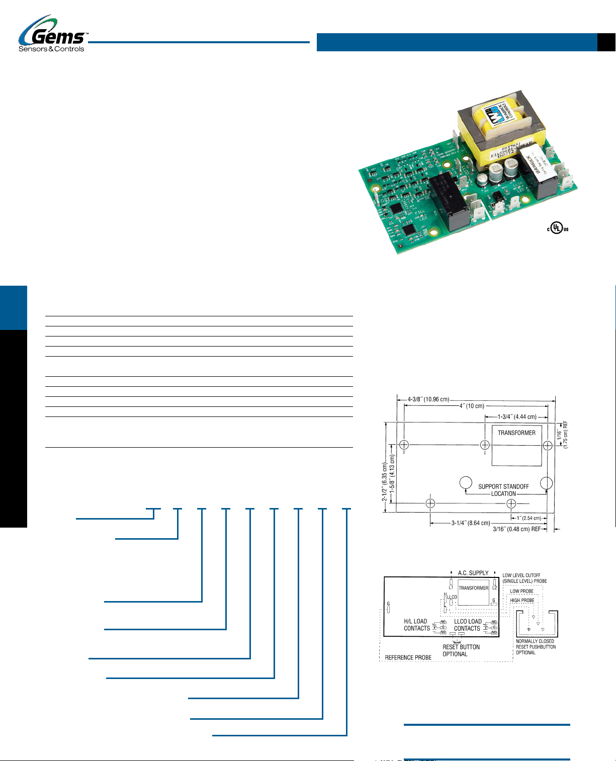
Series DF
Dual Function Controls
Solid State Reliability Spade Terminals for Easy Wiring
Compact Size Manual Reset (optional)
Meets CSD1 Requirements Power Outage Feature (optional)
U.L. “Motor Control” U.L. “Limit Control”
AC Current Minimizes Electrolysis
Optional Test Feature Time Out Option
Optional Dirty Electrode Detection
RELAY OUTPUT
Dual function Series DF models are designed to control two independent level
functions, one single-level control operation and one differential-level operation.
Optional Power Outage feature resets after nuisance outages. Optional Reset Button is
used when device has been deactivated due to low water condition. Reset is activated
only after water has returned to normal level. This control is ideal in applications on
boilers, food service equipment, and chemical delivery systems.
Specifications
Contact Design 1 N.O. & 1 N.C. (1 form C) extra function
WARRICK CONDUCTIVITY SENSORS
Contact Rating (120, 240 VAC) 10 amp Resistive 1/3 hp
Mode of Operation H/L Direct/Inverse, LLCO – factory set
Sensitivity 0-26K ohm, factory set
Primary Voltage 120 VAC, 240 VAC1, 24 VAC (+10%/-15%)
208/240: 187 V min. to 255 V max. VAC 50/60 Hz
Secondary Voltage 12 VAC
Temperature -40°F to +150°F (-40°C to +65°C)
Approvals U.L. 508 File # E44426, U.L. 353 File # MP1430
Terminal Style Spade connection
Options Time Delays, Manual Reset, Power Outage, Retrofit Plate,
Test Feature, Dirty Electrode Detection;
See page E-11 for descriptions
Notes:
1. 240 VAC and 208/240 VAC units do not carry U.L. Limit Control recognition.
How to Order
Use the Bold characters from the chart below to construct a product code.
DF X X X X X XX XX XX
1. Series
DF
2. Mode of Operation
Direct Inverse
A – 4.7K K – 4.7K
B – 10K L – 10K
C – 26K M – 26K
D – 50K N – 50K
E – 100K P – 100K
3. Supply Voltage
1 – 120 VAC; 2 – 240 VAC;
3 – 24 VAC; 8 – 208/240 VAC
4. Standoff Style*
A – 1/16˝ Panel C – Screw Mount
B – 1/8˝ Panel D – Retrofit
5. Enclosure
0 – None; 1 – NEMA 1; 4 – NEMA 4
6. Option Package
See page E-11, Chart B for code letter.
7. Time Delay (increasing level) H/L function
00-90 seconds; Blank 0 seconds
8. Time Delay (decreasing level) H/L function
00-90 seconds; Blank 0 seconds
9.Time Delay (decreasing level) LLCO function only
03-90 seconds; Blank 3 seconds
Series DF
Applications
• Dual Function
• Single-Level Service
• Differential Service
• Feedwater Control / Low-Water Cutoff
• High Level / Low Level
• Pump Down / High Level
Dimensions
Wiring
Note: For single level service, use “H” and “G” connections.
Socket Details and Option Availability
are located on web site.
1.66˝
8-PIN DIN SOCKET
BOTTOM
STANDOFFS, SOCKETS AND OPTIONS
Sockets and Standoffs – 16, 26 and DF Series Only
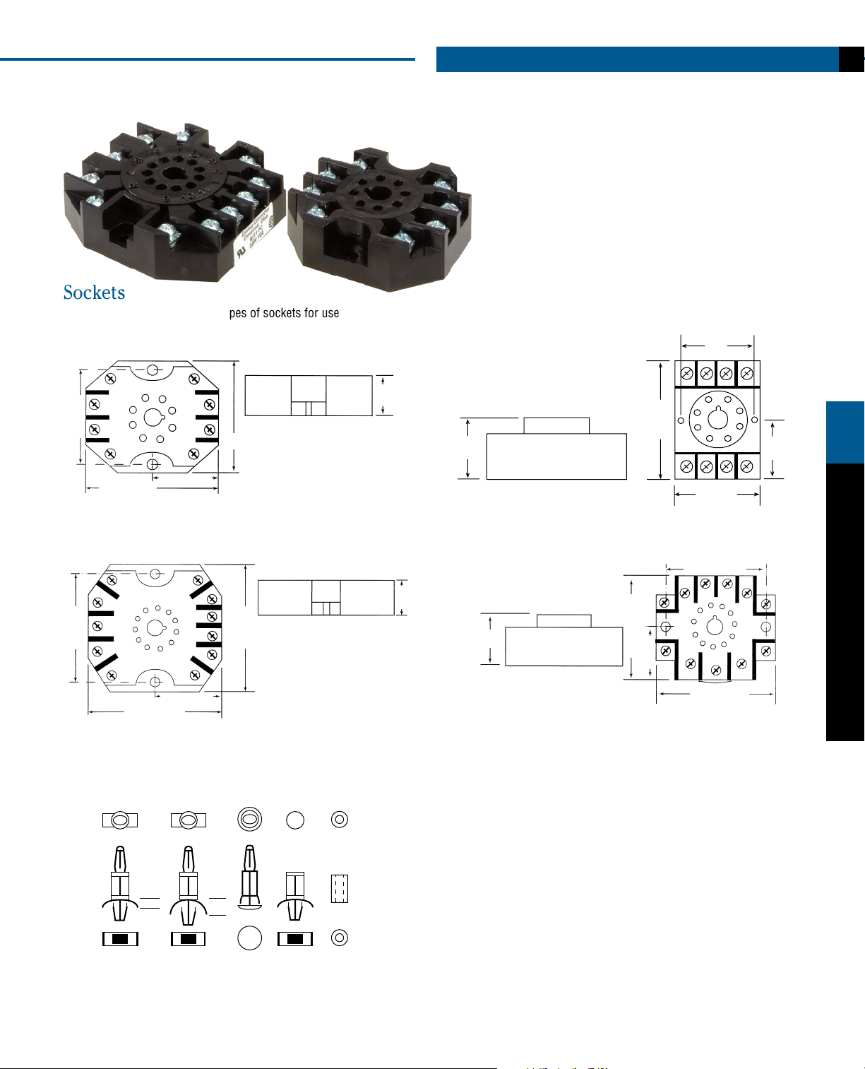
Sockets
Warrick provides four different types of sockets for use
with plug-in control modules.
8-PIN OCTAL SOCKET
0.625˝
(15.9 mm)
(42.16 mm)
2.31˝ (58.7 mm)
1.14˝ (28.96 mm)
2˝
(50.8 mm)
.980˝
(24.89 mm)
2.04˝
(51.82 mm)
1.30˝
(33.02 mm)
1.60˝
(40.64 mm)
1.01˝
(25.65 mm)
11-PIN OCTAL SOCKET
2.21˝
(56.13 mm)
1.3˝ (33.02 mm)
2.60˝ (66.04 mm)
2.53˝
(64.26 mm)
Standoffs
Warrick provides four different types of standoffs
designed to connect circuit boards to panels.
TOP
VIEW
SIDE
VIEW
VIEW
1/16˝
STANDOFF
1/16˝
1/8˝
STANDOFF
1/8˝
RETROFIT
STANDOFF
CIRCUIT
BOARD
STANDOFF
SCREW
MOUNT
STANDOFF
0.625˝
(15.88 mm)
1.0˝
(2.54 mm)
11-PIN DIN SOCKET
2.04˝ (51.82 mm)
1.02˝
(25.91 mm)
2.04˝ (51.82 mm)
2.33˝ (59.18 mm)
WARRICK CONDUCTIVITY SENSORS
 Loading...