

WARREN-SHERER S3(J), S3(j)C Installation And Operaion Manual
. . .
. . ‘. Y’,.‘ . .
,..
. . . . . :r *,,.
,’ I
*’ : , * ., I c, * :‘y:.’
. .;
-
1
WARREN//SHERER ..(.; /-;::_:~;. :;:. ;.;.::,s;f.. -; ‘,-r :- .T .,
DIVISION OF KYSOR INDUSTRIAL CORPORATION ” .‘.: ,‘. ,‘. ’ .-“’ * ‘: : ’
- ‘-
.
‘,, ’
. : r .
.
-
1600-ROCKDALE INDUSTR'iAL BLVD., 60NYERS, GEORGIA ;0207,404483&600 .
INSTALLATION AND OPERATING INSTRUCTIONS
FOR
S3J, S3JC, S3, S3C MODELS
.m
SERVICE DELI/MEAT CASES
. . . . . . . . .._.... . . . . . . . . . .
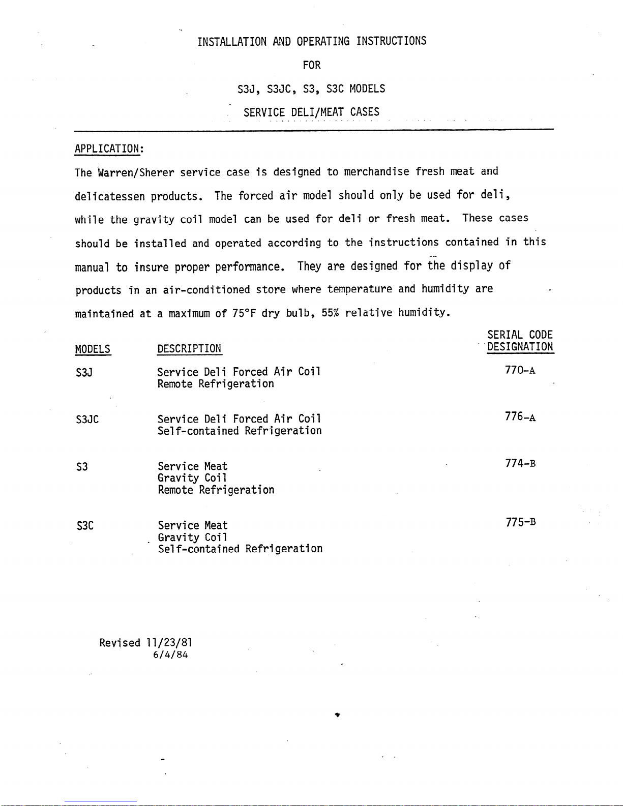
APPLICATION:
The kJarren/Sherer service case is designed to merchandise fresh meat and
delicatessen products.
The forced air model should only be used for deli,
while the gravity coil model can be used for deli or fresh meat. These cases
should be installed and operated according to the instructions contained in this
manual to insure proper performance.
They are designed for the display of
products in an air-conditioned store where temperature and humidity are
4
maintained at a maximum of 75*F dry bulb, 55% relative humidity.
I
SERIAL CODE
MODELS
DESCRIPTION
"DESIGNATION
S3J
Service Deli Forced Air Coil
770-A
Remote Refrigeration
e
S3JC
Service Deli Forced Air Coil
Self-contained Refrigeration
s3
Service Meat
Gravity Coil
Remote Refrigeration
s3c Service Meat
L
Gravity Coil
Self-contained Refrigeration
776.~
774-B
775-B
Revised 11/23/87
6/4/84
9
GENERAL
These display refrigerators may be installed individually or in a continuous
line-up consisting of several 8-foot and V-foot sections by using a joint trim
.
kit A plexiglass divider'kit must be used between cases operating on different
refrigeration systems.
Divar will be factory installed if specified on order.
SHIPPING DAMAGE
All equipment should be examined for shipping damage before and during unloading.
If there is any damage,
the carrier should 'be notified immediately and an inspection
requested. The delivery receipt "must"
be noted that the equipment was received
damaged. If damage is of a conceamnature you must contact the carrier immediately
or
no later than three (3) days following delivery.
A-claim must be filed with the
carrier by the consignee for all damages.
- --
- _ -
LOCATION
This refrigerator must be located on a firmly based floor and leve
or minus l/16".
Use shims provided to level your refrigerator.
JOINING
Two or more fixtures of like models can be joined together to form
line-up. Instructions for joining fixtures are included in the jo
ed within plus
a continuous
nt kit.
Before-lining up refrigerator, inspect refrigeration lines, electrical connections,
and controls to insure refrigerators are in proper line-up and are in the proper
sequence.
Note: THESE REFRIGERATORS ARE LINED UP AT THE FACTORY AND ARE NUMBERED.
. .
. .i
: INSURE THEY ARE LINED UP IN THE FIELD IN THE SAME SEQUENCE NUMBER.
WASTE OUTLET .
These cases are equipped with a l-l/Z'* FPI waste outlet connection which terminates
in the center of the refrigerator below the insulated bottom. A l-l/Z" galv,
. water seal trap is provided for field installation.
INSTALLING DRIP-PIPE
Improperly installed drip pipes can seriously effect the operation of this
equipment and result in increased maintenance cost.
general rules for drip pipe installation.
Listed below are some \..
1. Never use a double water seal.
2. Never use a pipe smaller than the size pipe or water seal supplied with the
equipment.
3:Always provide as much as fall as possible in drip pipe. (l** fall for each
4' of drip pipe).
4. Avoid long runs in drip pipe which make it impossible to provide maximum fall
7iijZpe.
5. Provide a drip space between drip pipe and-floor drain or sewer connection.
6. Do not allow drip pipe to come in contact with uninsulated suction lines,
nhichwill cause the condensation from your refrigerator to freeze.
Rev. 6/4/84
1)
2
--
SXJ)
,
CLEANING
To 'insure minimum maintenance cost, cabinet should be emptied and throughly
washed out once a week.
A mild soap and water solution is recommended for painted
surfaces of the cabinet.
Do not use cleaners containing abrasive materials which
will scratch or dull finish.
The waste outlet should be flushed with a bucket
of water following each cleaning.
Caution: Never introduce water into the fixture faster than the waste outlet
can carry it away.
When cleaning lighted shelves, wipe down with a wet sponge or cloth so that water
does not enter the light rails.'
DO'NOTUSE'A'HOSE'ORSUBMERGE SHELVES IN'lrJATER.
BE SURE REFRIGERATION IS SHUT-OFF AND ALL ELECTRICAL IS OFF BEFORE WASHING YOUR
REFRIGERATOR.
LOADING
Merchandise should not be placed in the fixture until all controls have been
adjusted and the refrigerator is at proper temperature.
At no time should the fixture be stocked beyond the load line or over the front
. -.
edge of adjustable shelves.
In doing so, you will seriously affect the performance
which will result in higher product temperatures and increase operating costs.
ELECTRICAL
All field installed wiring must comply with the NATIONAL ELECTRICAL CODE AND
LOCALCODES.
ELECTRICAL JUNCTION
On these cases, an electrical junction box is provided for field connections.
The junction box is located at the left rear of the case and contains the case
;
thermostat an6 all lighting ballasts. \On self-contained models, a separate -
circuit should be provided for the condensing unit. '
ELECTRICAL CONNECTIONS
ml field connections
are
made in the electrical junction box.
Make sure that proper voltage is supplied to your refrigerator. Check refrigerator
nameplate for correct circuits, volts, and amps.
*ALL'REFRIGERATORS'MUST BE'GROUNDED.
When refrigerators are-mu1 tiplexed, add the total of these amperage values to
determine wire size and circuit protection.
Make sure that proper wire size and branch circuit protection are employed for
safe operation.
.
.
Chart #l shows the electrical ratings for your refrigerator. This is the same
information that appears on your refrigeration nameplate.
REFRIGERATION FAN MOTORS (S3J Only)
The fan motors employed are permanently oiled for the life of the-motor and
require no periodic maintenance.
They are wired according to the enclosed
wiring diagram and'MUST'RUN%ONTINUOUSLY.
+
3
- -
WJ)
EXPANSION VALVE -*
The expansion valve furnished with your refrigerator has been sized for maximum
coil efficiency.
To adjust superheat, place a thermocouple under the expansion
valve bulb. Read the suction line pressure as near coil as possible. (If, at
the condensing unit, estimate suction line loss at 2 PSIG). Convert coil suction
pressure to temperature. The difference between coil temperature and the
thermocouple temperature is superheat. (Use average superheat when expansion
valve is hunting). Do not set superheat until cases have pulled down to operating
temperature and never open or close valve over l/Z turn between adjustments and
allow 10 minutes or more between adjustments. Superheat should be set to 6-8OF.
REFRIGERATION LINES
Refrigerant connections (suction & liquid) are stubbed underneath the case.
Cases multiplexed together must be field connected by running refrigerant
lines in the space under the case. The field installed suction lines must be
insulated to prevent condensation accumulation on the floor. See the section
on "Recommended Piping Practices" for additonal details on piping practices.
IMPORTANT A SEAL AROUND LINES AFTERCONNECTIONS ARE'MADE. KEEP DIRECT FLAME
FROM BOTTOM OF REFRIGERATOR, AS HEAT WILL DISINTEGRATE THE BOTTOM AND INSULATION.
USE A HEAT SHIELD WHEN WELDING NEAR THE BOTTOM OF THE CASES.
REFRIGERANT
R-12 expansion valves are standard. If other refrigerant is used, the order
must specify the expansion valve to be supplied.
*,HEAT EXCHANGER (S3J
only)
Heat exchangers are standard in these refrigerators. They aid to increase
operating efficiency and reduce frosting and flood-'back to compressor.
OPERATION
On single condensing unit systems,
a thermostat should be used to control
temperatures.
The thermostat bulb is mo[lnted on the rear baffle on S3.modeld and
'.in the discharge air on the S3J,
On parallel units, temperature control can be .
provided by EPR valve and thermostat.
Chart #2 shows approximate settings for .
merchandisers. Since many variables are present in each-installation, such as 'i
. store temperature, length of tubing runs, temperature desired in refrigerator, etc.,
'Chart #2 is only a guide for-the installer.
DEHYCRATION OF REFRIGERATION SYSTEMS
Please read'ca~~fully.befd~~'~l~~i~g'~~~t~m intd operation. After laying
. refrigerant lines, they should be blown out before making final connection at
fixture or condensing unit.
Use dry nitrogen to prevent any foreign matter
being left in the lines.
Keep pressure below 250 pounds. To prevent scaling
due to brazing, dry nitrogen should be allowed to flow through lines while
brazing operations are taking place.
. After the refrigeration system has been pressure-tested and proven leak-free,
it is recommended that the system be dehydrated with a vacuum pump to 100 microns
for the first two evacuations and 500 microns on the third. The triple evacuation
method requires evacuating the system three successive times and breaking each
vacuum with dry refrigerant.
Allow the pressure to rise above atmospheric pressure.
Revised 11/23/81
9
4
LI -
WJ)
DEF.ROST CYCLE
Off-time defrost is standard on these models.
The fans run continuously on the
S3J.
Defrost termination is by time (fail safe).. es f '-
( See Chart #2 for defrost
settings.
Self-Contained Models
The self-contained S3(J)C uses a Copeland 'F" line air cooled condensing unit.
The condensing unit is located under the display area. R-12 is the standard
refrigerant in this system.
The unit may be serviced by sliding out of case.
This is done by removing
the retaining clamps on back of the case and pulling
the unit out carefully.
Care must be taken so as not to block the condenser air
inlet and outlet.
.-m
Revised 11/23/87
m
v?
5
- -
WJ)
 Loading...