

Warren Controls E024, E026, EO29, E030, EO25 Installation, Operation And Maintenance Instructions
Page 1
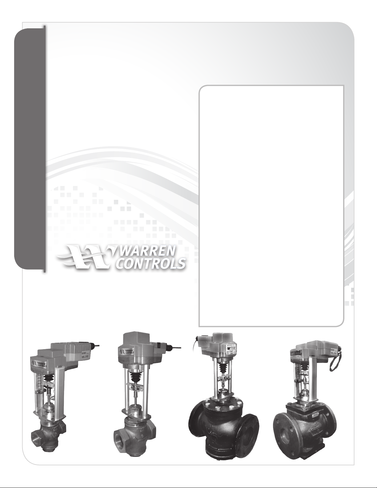
ELECTRIC ACTUATOR
E024, EO25, E026, EO29 & E030
Installation Operation and Maintenance Instructions
TABLE OF CONTENTS
Electric Actuator Specifications...................................... 2
Overview ................................................................................ 3
Actuator Wiring Diagrams ................................................ 4
VMS-35 Specifications and Wiring Diagram .............. 5
VMS -35 Installation and Testing .................................... 6
VMS -35 Battery Replacement ........................................ 7
Removal of E024 & E025 ................................................... 8
Installation of E024 &E025 ............................................... 9
Removal of E026, E029 & E030......................................10
Installation of E026, E029 & E030 ................................. 11
Set-up ....................................................................................12
Control Action ....................................................................13
HVAC/BAC ELECTRIC IOM
Power Failure Direction E025 & E026 .........................14
Indicator Lights ..................................................................15
Installation Drawings ................................................ 16-17
Addendum A ................................................................ 18-20
Addendum B ................................................................ 21-25
HVAC_BAC_ELECTRIC_IOM_RevCa_0219
92500115 RevD
Page 2
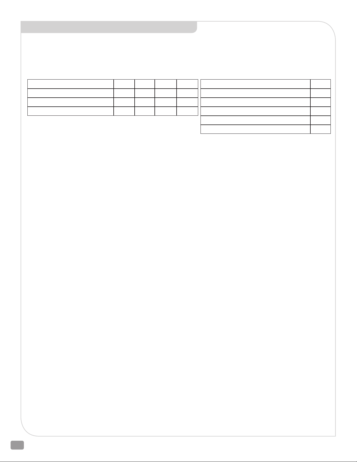
ELECTRIC ACTUATOR SPECIFICATIONS*
Valve Usage: E024, E025 [Valve sizes 1/2 to 4 Inch]
E026 [Valve sizes 1 to 6 Inch]
E029, E030 [Valve sizes 1-1/4 to 10 Inch]
______________________________________________________________________________________________
Power supply: 24 VAC ± 20% 50/60 Hz, 24 VDC ± 10%
______________________________________________________________________________________________
Power Requirements E024 E025 E026 E029
Power consumption running 2 W 3 W 5 W 6 W
Power consumption holding 1.5 W 2 W 2 W 1.5 W
Transformer sizing (24 VAC Class 2) 4 VA 7 VA 9.5 VA 11 VA
Power Requirements E030‡
Power consumption running (Battery charging)
Power consumption running (Battery charged)
Power consumption holding (Battery charging)
Power consumption holding (Battery charged)
Transformer sizing (24 VAC Class 2)
______________________________________________________________________________________________
Timing: 90 seconds full stroke max
______________________________________________________________________________________________
Control Signal: 2-10 Vdc (default), 4-20 mAdc [with KR500 (resistor kit)]
______________________________________________________________________________________________
Feedback Signal: 2-10 Vdc
______________________________________________________________________________________________
Signal Failure Direction: E024, E029, E030 Fail Closed or Lower Port Closed (default), or
Fail Open or Upper Port Closed
E025, E026 Fail Closed or Lower Port Closed (default), or
Fail Open or Upper Port Closed
______________________________________________________________________________________________
Power Failure Mode: E024, E029 Fail-In-Place
E030 Fail-Safe to Signal Failure Direction
E025, E026 Fail Closed or Lower Port Closed (default), or
Fail Open or Upper Port Closed
______________________________________________________________________________________________
Capacitor: E025, E026 Capacitor charge time 5 to 20 seconds
______________________________________________________________________________________________
Manual Override: Yes, with supplied Allen Key (4mm E024, E025 / 5mm, E026, E029, E030)
______________________________________________________________________________________________
Construction: Aluminum die cast Yoke, plastic Housing
______________________________________________________________________________________________
Connections: 3 foot long 4 Conductor 18 gauge wire, pigtail (may include fifth pink colored conductor
only used for factory programming. Do Not Use or Connect)
______________________________________________________________________________________________
Enclosure Type: NEMA 2, IP54, UL 2
______________________________________________________________________________________________
Noise Level: E024, E025 45 dBA
E026 60 dBA
E029, E030 65 dBA
______________________________________________________________________________________________
Environmental: Operating: Ambient + 32°F to +122°F (0 to +50°C)
Humidity: 5 to 95% RH non-condensing
Storage: -40°F to +176°F [-40°C to +80°C]
______________________________________________________________________________________________
Orientation: Factory Aligned per drawings
______________________________________________________________________________________________
Mounting: Vertical above centerline of valve
______________________________________________________________________________________________
Safety Agency Listing: CE, cULus
16 W
11 W
11.5 W
6.3 W
21 VA
‡E029 w/VMS-35
* See page 5 for VMS-35 Specifications
2600 Emrick Blvd • Bethlehem, PA 18020 • USA • 800-922-0085 • www.warrencontrols.com
2
Page 3
OVERVIEW
ADAPTION POWER
The actuators feature a native
2-10 Vdc Control Signal.
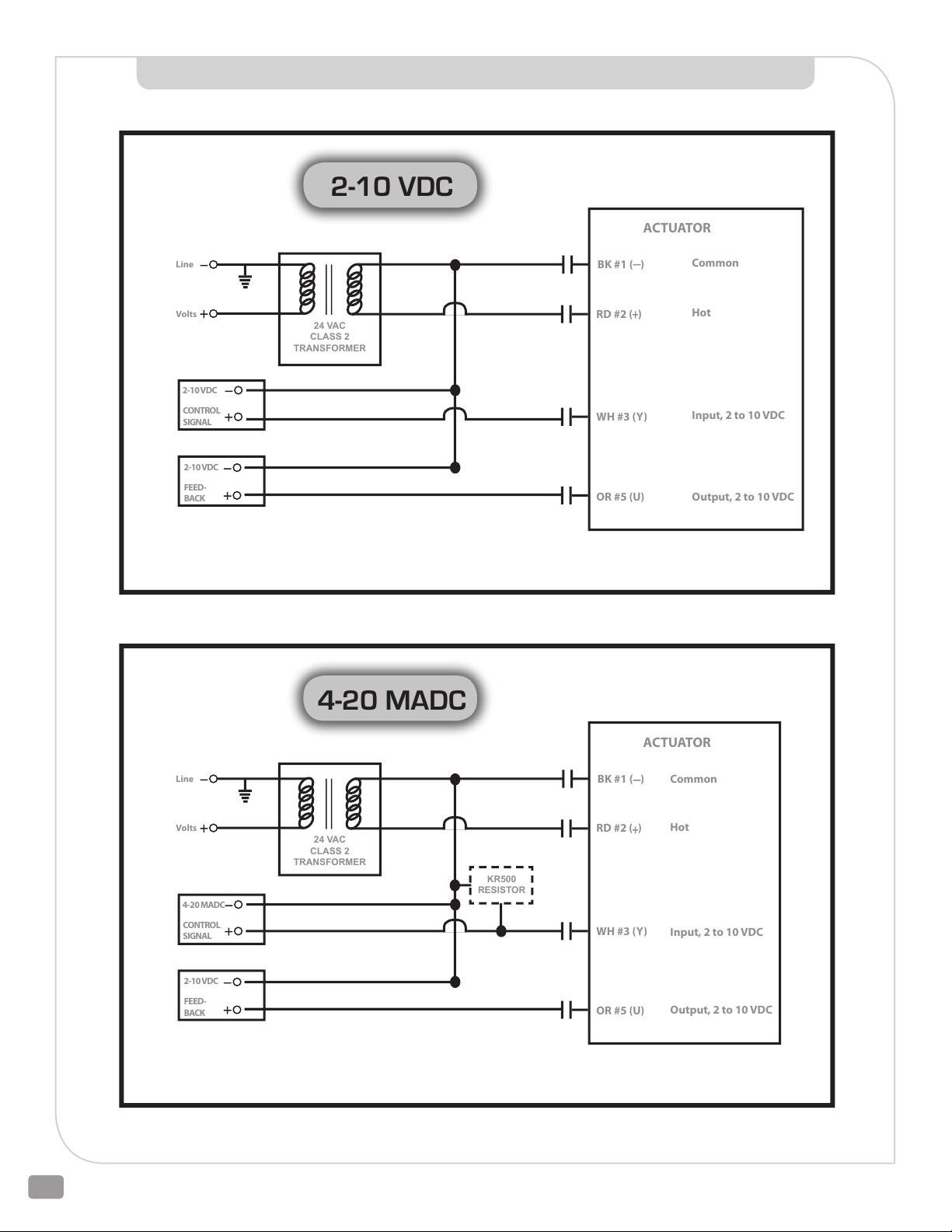
Installation of the KR500
Resistor Kit converts the
Control Signal input to 4-20
mAdc. When using 4-20 mA
input, terminate the 500 ohm
resistor from the KR500 resistor
kit between the White and
Black actuator wires. When
using the VMS-35, this can be
easily done between the NO1
and LN terminals for Actuator
1 and between the NO2 and LN
terminals for Actuator 2.
A single wire brings a 2-10 Vdc
Feedback Signal. The Feedback
Signal is not available using
4-20 mAdc.
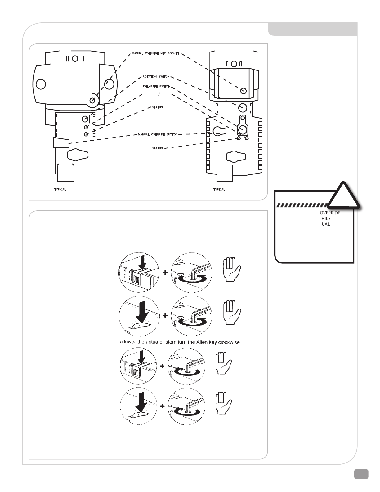
(E024, E029, E030) (E025, E026)
Manual Override is possible by turning off the power, pressing the Manual Override button
and rotating the supplied Allen key in the Hex Override Socket.
To raise the actuator stem turn the Allen key counter-clockwise.
E024
Engage the manual override:
•
The override button can
lock in place for NONCAPACITOR E024, E029
and E030 actuators.
Press the button down
and into the actuator
to lock. The OVERRIDE
BUTTON will remain
down and will need to
be pressed to return
to its original position.
•
The button must be
continuously pressed
completely down
throughout travel for
E025 AND E026 actuators
with CAPACITORS.
E029
E030
E025
E026
E024
E029
E030
E025
E026
WARNING: Do not force or turn the HEX OVERRIDE SOCKET when the OVERRIDE BUTTON is not
pressed. Doing so may cause damage to the actuator gears.
DANGER
PRESS THE MANUAL OVERRIDE
BUTTON IN FIRMLY WHILE
OPERATING THE MANUAL
OVERRIDE. FAILURE TO DO SO
WHILE THE ACTUATOR IS POWERED
OR BEING DRIVEN TO THE POWER
FAILURE DIRECTION CAN CAUSE
SERIOUS PERSONAL INJURY AND
DAMAGE THE ACTUATOR.
The Rotation Switch can be
adjusted to set the direction
the Control Signal opens and
closes the valve (and Loss
of Signal direction in some
actuators) in the field without
actuator removal.
Adaption (Auto-Calibration
- green LED), a combined
Adaption/ Power button to
reset and relearn the valve
stroke as well as indicate the
actuator is powered. When the
Button is pressed, the actuator
will drive one full cycle to
its mechanical end stops OR
the valves mechanical seats.
Upon completion of this cycle
the actuators working range
(Control Signal, Feedback
Signal and running time) will
be adjusted to the actual
stroke of the actuator.
Status (yellow LED) to confirm
communication.
!
HVAC_BAC_ELECTRIC_IOM_RevCa_0219
3
Page 4
2-10 VDC
Line
Volts
24 VAC
CLASS 2
TRANSFORMER
2-10 VDC
CONTROL
SIGNAL
2-10 VDC
FEED-
BACK
ACTUATOR
BK #1 ( )
RD #2 ( )
WH #3 (Y)
OR #5 (U)
Common
Hot
Input, 2 to 10 VDC
Output, 2 to 10 VDC
4-20 MADC
Line
Volts
24 VAC
CLASS 2
TRANSFORMER
4-20 MADC
CONTROL
SIGNAL
2-10 VDC
FEED-
BACK
ACTUATOR
BK #1 ( )
RD #2 ( )
WH #3 (Y)
OR #5 (U)
Common
Hot
Input, 2 to 10 VDC
Output, 2 to 10 VDC
KR500
RESISTOR
ACTUATOR WIRING DIAGRAMS - PROPORTIONAL CONTROL
2600 Emrick Blvd • Bethlehem, PA 18020 • USA • 800-922-0085 • www.warrencontrols.com
4
For On-O control see Addendum B on pages 21-25.
Page 5

VMS-35 BCM
Power
24 VAC
HOT
Existing Jumper
L LN RC LN TG BT AC LNNC1 C1 NO1
NC2 C2
NO2
CONTROL SIGNAL (S)
(RECOMMENDED)
(RECOMMENDED)
OUTPUT TO
ACTUATOR A
OUTPUT TO
ACTUATOR B
(IF USED)
Actuator BActuator A
1. The VMS-35 can power one (1) or two (2) actuators.
2. Energize 24 VAC before connecting red lead to battery.
3. Also read actuator wiring and setup instructions.
4. To prevent signal interference proper signal wire cable
shielding is recommended.
5. When using long wire runs and a 2 – 10 Vdc signal,
signal and power cables should be run in separate
conduits to avoid interference.
NOTES
VMS-35
OR#5(U)
WH#3(Y) RD#2(+) BK#1(-)
OR#5(U)
WH#3(Y) RD#2(+) BK#1(-)
BACKUP CONTROL MODULE
SPECIFICATIONS
Actuator Usage: E030 (E030 includes a VMS-35 BCM), E029, E024
Power supply: 24 VAC ± 20% 50/60 Hz
Power Requirement: 40 VA MAX
Power Output: 24 VAC 25VA 25W Total
Number Actuators: One or Two
Construction: Battery w/Circuit Board, Charger and Transformer
Enclosure Type: NEMA 4X, IP66, UL 4X, CSA 4X
Flame Retardant: UL 50
Construction: UV Stabilized Fiberglass Reinforced Polyester,
Polycarbonate Hinge and Closed Cell Neoprene Gasket
Connections: Two 1/2 IN conduit with one plug
Number Batteries: One
Initial Charge: 2-4 hours
Output Cycle Time:
6.5 Minutes from loss of power until circuit board times out
Battery Life: Up to 5 years … Replacement battery
model UB1213 / 12V, 1.3 Ah
Mounting: Feet for Wall Mount (4.91” x 8.75” centers)
Environmental: Operating/ Storage: Ambient +32°F to +104°F
(0 to +40°C) – due to battery
Weight: 4.25 lbs (2 kg)
Safety Agency Listing: Not listed
VMS-35 WIRING DIAGRAM - PROPORTIONAL CONTROL
For On-O control see Addendum B
on pages 21-25.
TERMINALS
L System Power 24 VAC (+)
LN System Neutral (-)
RC Remote Control
BT Battery Test (+)
TG Test Ground (-)
C1 Control Signal 1st Actuator (+)
C2 Control Signal 2nd Actuator (+)
NC1 Not Used
NC2 Not Used
NO1 Relay Normally Open 1st Actuator
NO2 Relay Normally Open 2nd Actuator
AC 24 VAC Out (+)
Operation:
Proportional Normal: Terminal L is connected to 24 VAC building
power. Terminal LN completes the circuit to BK. Actuator responds to
modulating input signal.
Power Failure: Terminal AC changes to 24 V square wave from battery/
inverter. A relay breaks the connection between Terminals C1 and NO1
forcing the actuator to return to the rotation switch position (See page
13 for explanation of rotation switch position).
Loss of Signal: Terminal AC uses 24VAC building power. The control
signal is broken forcing the actuator to return to the rotation switch
position (See page 13 for explanation of rotation switch position).
HVAC_BAC_ELECTRIC_IOM_RevCa_0219
5
Page 6

INSTALLATION - PROPORTIONAL CONTROL
1. Disengage the 24 VAC building power circuit before wiring. Verify that the battery inside the VMS-35 has its wires disconnected and
leave them that way for now. Disconnect them if they are connected.
2. Connect the VMS-35 to the actuator(s) as shown on wiring diagram. The VMS-35 can power one or two actuators.
Actuator A: Connect terminal N01 to white wire from actuator to drive the valve stem to the rotation switch position. Connect terminal
AC to red wire from actuator to provide power. Connect grounded reference – negative/black wire from actuator to terminal LN. Also
connect the control signal (-) to the black wire from the actuator. Connect terminal C1 to the control signal positive (+). If the control
signal is 4-20mADC a KR500 500 ohm resistor is required. Terminate the resistor between terminals N01 an LN.
Actuator B: Connect terminal N02 to white wire from actuator to drive the valve stem to the rotation switch position. Connect terminal
AC to red wire from actuator to provide power. Connect grounded reference – negative/black wire from actuator to terminal LN. Also
connect the control signal (-) to the black wire from the actuator. Connect terminal C2 to the control signal positive (+). If the control
signal is 4-20mADC a KR500 500 ohm resistor is required. Terminate the resistor between terminals N02 an LN.
3. While still disconnected, wire the VMS-35 to 24 volts AC power. Connect the hot to terminal L then neutral to terminal LN.
4. Engage the 24 VAC building power.
5. Verify that building power is live then connect the loose red wire inside the VMS-35 enclosure to the positive (+) battery terminal and
the black wire to the negative (-) battery terminal.
NOTE: Engage the 24 VAC power to the VMS-35 before connecting the battery. Connecting the battery first causes the VMS-35 to go
into the power failure mode. If there are conditions other than power failure during which the actuator should be driven to the rotation
switch position (See page 13 for explanation of rotation switch position), replace the jumper between RC & LN with a contact that opens
on demand.
For On-O control see Addendum B on pages 21-25.
TESTING
Disconnecting the jumper between RC & LN, with building power on, will drive the actuator to the rotation switch position (See page 11
for explanation of rotation switch position).
Testing the VMS-35 and the charging system and battery is recommended yearly. To test charging measure the voltage between terminals
TG & BT. TG is negative. When the power supply is charging correctly the voltage will be 13 - 14 volts DC. To test the battery disconnect
LN or L, wait for the actuator to return to the rotation switch position (See page 13 for explanation of rotation switch position) and then
measure the voltage between TG & BT. A good and adequately charged battery will be between 10 - 12 volts DC.
The VMS-35 is a standby power supply.
It is intended to drive an actuator to either open or close a valve during a power failure. The VMS-35 can power one or two actuators.
2600 Emrick Blvd • Bethlehem, PA 18020 • USA • 800-922-0085 • www.warrencontrols.com
6
Page 7
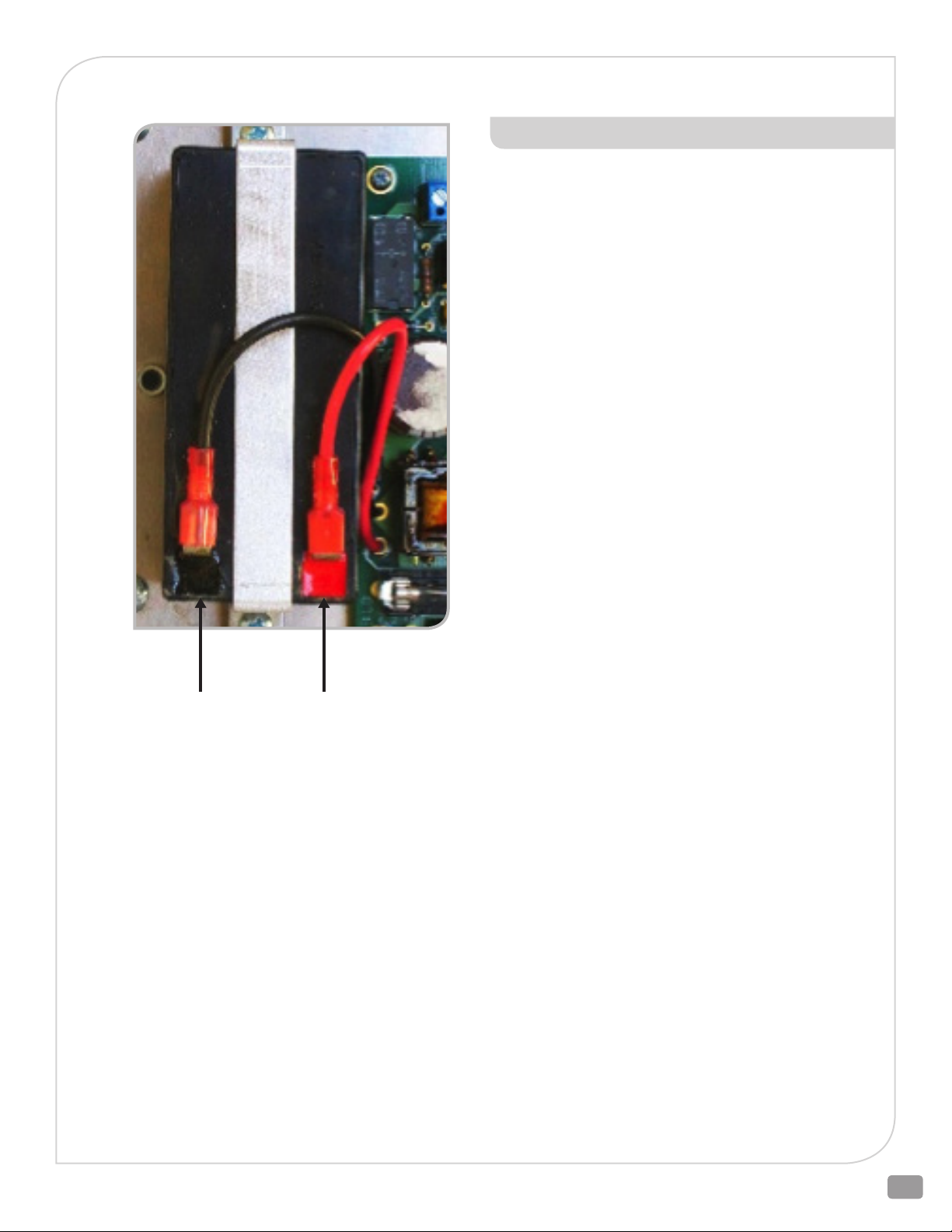
VMS-35 (UB1213) BATTERY REPLACEMENT
PROCEDURE:
NOTE Normal valve operation under 24 VAC power need not be interrupted
during battery replacement; however, the fail-safe function will not be avail-
able until the new battery is in place, connected and sufficiently charged (typi-
cally 2-4 hours).
1. Refer to the picture (left) to locate and disconnect the Red and
Black wires from the battery.
2. Remove the two battery mounting bracket screws and remove
the battery and bracket.
3. Place the bracket over the new battery and install the
assembly as shown, using the two screws removed in step 2
(above).
4. Connect the Black wire to the black (unmarked) terminal.
5. With 24 VAC power present, connect the Red wire to the
red terminal. VMS-35 circuitry will automatically charge the
battery. (If 24 VAC is not present, the valve may move to its
fail-safe position, depending upon residual charge in the new
battery.)
Black Red
6. Recycle or dispose of the old battery properly. Do not
incinerate!
HVAC_BAC_ELECTRIC_IOM_RevCa_0219
7
Page 8
READ ALL INSTRUCTIONS CAREFULLY BEFORE BEGINNING.
REMOVAL OF E024 & E025
ACTUATORS FROM VALVE
SEE DRAWING D3400024 on page 16
THESE INSTRUCTIONS TREAT THE ACTUATOR ITEM 1 AND LINKAGE BASE
ITEM 17 AS AN ASSEMBLY. FOR INSTRUCTIONS ON HOW TO REMOVE THE
ACTUATOR AND THE LINKAGE BASE AS SEPARATE ITEMS SEE ADDENDUM A
ON PAGE 18.
1) Remove line pressure and isolate valve in piping.
2) Operate actuator so plug is off seat(s) or travel stop in valve.
3)
Remove power and signal from actuator. For E025, after power
is removed, cycle Fail-Safe Switch from Up Arrow to Down
Arrow until actuator stem no longer moves. Adaption/Power
(green LED) changes from blinking to off. Return Fail-Safe
Switch to original position. If necessary use the manual override
to operate actuator so plug is off seat(s) or travel stop in valve.
(See manual override on page 3)
WARNING: DO NOT FORCE OR TURN THE MANUAL
OVERRIDE WHEN THE MANUAL OVERRIDE
BUTTON IS NOT PRESSED. DOING SO MAY CAUSE
DAMAGE TO THE ACTUATOR GEARS.
5) Use actuator manual override to raise the stem connector
until the stem adapter is disengaged (See manual override on
page 3).
WARNING: DO NOT FORCE OR TURN THE MANUAL
OVERRIDE WHEN THE MANUAL OVERRIDE
BUTTON IS NOT PRESSED. DOING SO MAY CAUSE
DAMAGE TO THE ACTUATOR GEARS.
WARNING: DO NOT LOOSEN THE FACTORY SET
ADJUSTABLE HEIGHT SCREWS ON THE SIDES OF
THE ACTUATOR YOKE LINKAGE.
6) Loosen yoke locknut (Item 3) until it is free of bonnet.
7) Remove spacer ring (Item 2).
8) Remove actuator from valve.
WARNING: DO NOT LOOSEN THE FACTORY SET
ADJUSTABLE HEIGHT SCREWS ON THE SIDES OF
THE ACTUATOR YOKE.
9) Hold jam nut (Item 4) on valve stem and turn the stem adapter
(Item 5) to disengage from valve stem.
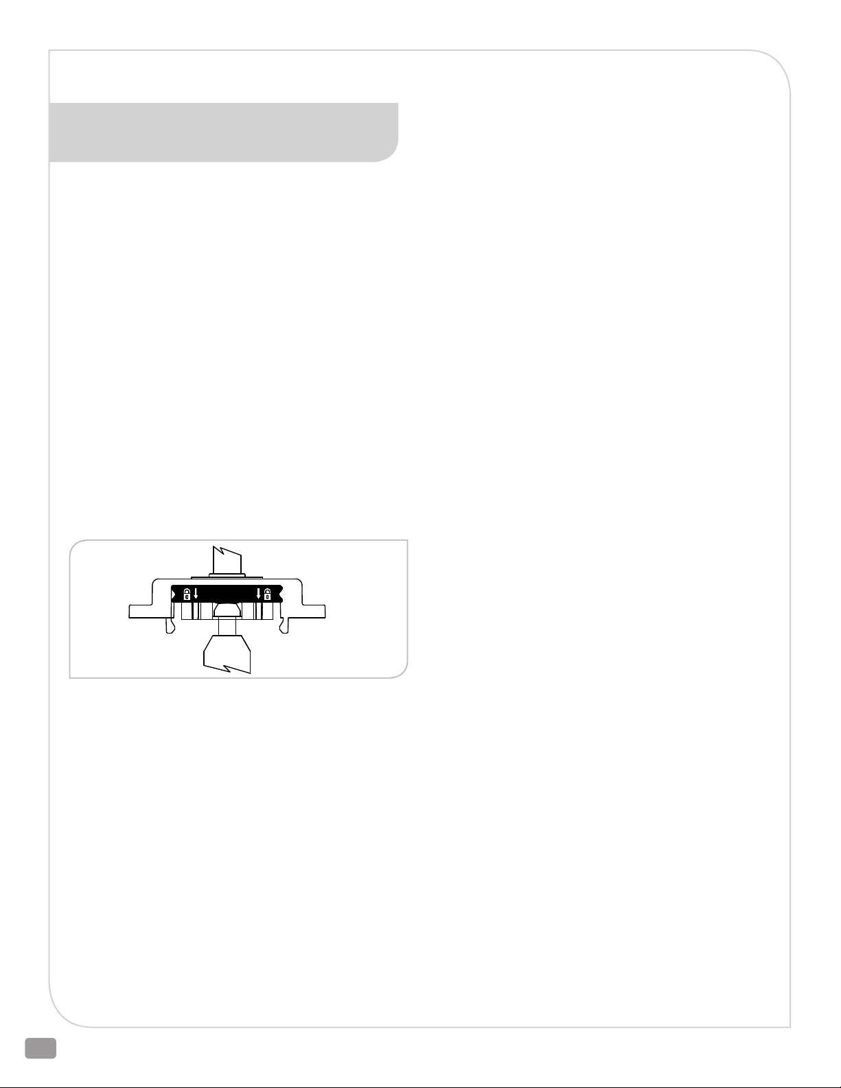
4) Unlock stem connector clamp, use fingers on the front and
back sides of black lock assembly to evenly raise the lock
assembly.
WARNING: WHEN HANDLING THE ACTUATOR TAKE
CARE NOT TO DAMAGE THE STEM CONNECTOR
CLAMP AND CROSS BAR ASSEMBLY.
WARNING: THE VALVE STEM SHOULD NEVER BE
TURNED WHILE THE PLUG IS IN CONTACT WITH
THE SEAT OTHERWISE THE SEATING SURFACES
WILL BE DAMAGED VOIDING THE WARRANTY.
10) Remove stem adapter from valve stem.
11) Remove jam nut from valve stem.
2600 Emrick Blvd • Bethlehem, PA 18020 • USA • 800-922-0085 • www.warrencontrols.com
8
Page 9
READ ALL INSTRUCTIONS CAREFULLY BEFORE BEGINNING.
INSTALLATION OF E024 & E025
ACTUATORS ON THE VALVE
SEE DRAWING D3400024 on page 16
THESE INSTRUCTIONS TREAT THE ACTUATOR ITEM 1 AND LINKAGE BASE
ITEM 17 AS AN ASSEMBLY. FOR INSTRUCTIONS ON HOW TO INSTALL THE
ACTUATOR AND THE LINKAGE BASE AS SEPARATE ITEMS SEE
ADDENDUM A ON PAGE 19.
THE SILVER SPACER RING THAT COMES WITH THE ACTUATOR MUST BE
ASSEMBLED ON TOP SIDE OF YOKE WITH TURNED DOWN (MACHINED) SIDE
FACING DOWN AS SHOWN ON DRAWING.
1) Push valve stem down until plug is seated. Note stem location.
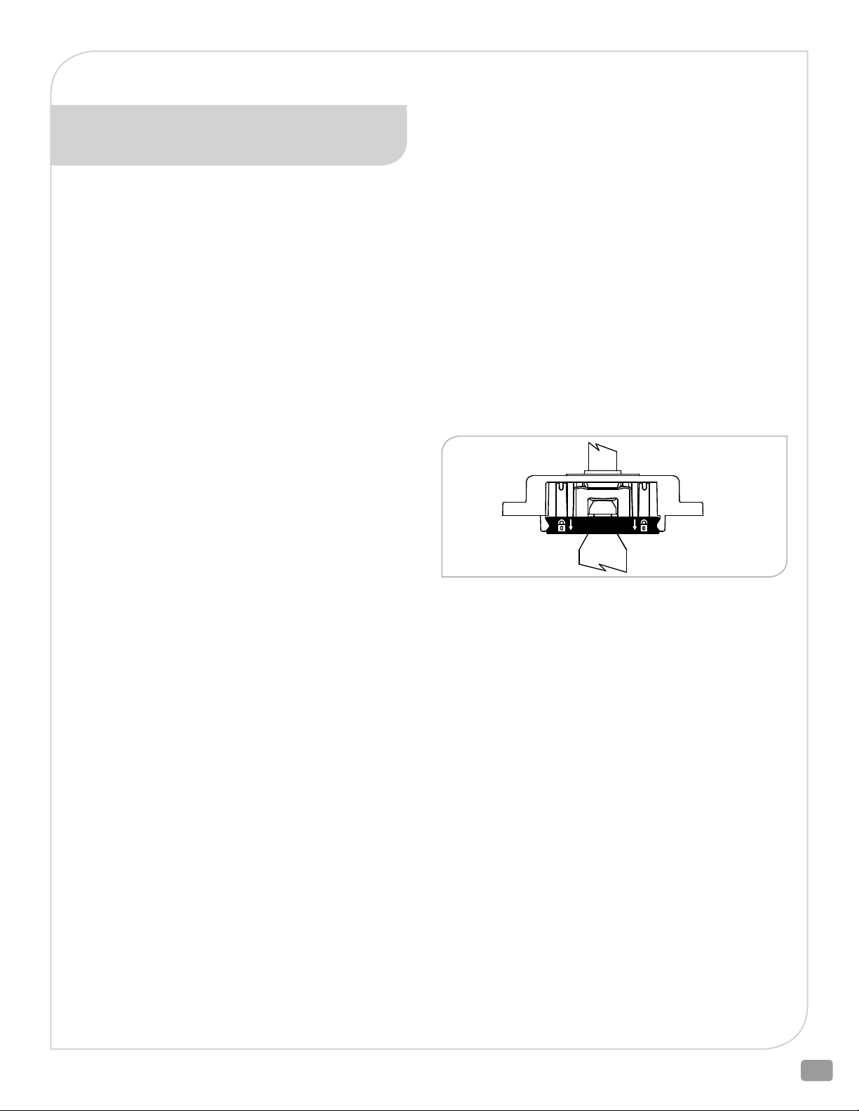
2) Unlock stem connector clamp, use fingers on the front and
back sides of black lock assembly to evenly raise the lock
assembly.
WARNING: WHEN HANDLING THE ACTUATOR TAKE
CARE NOT TO DAMAGE THE STEM CONNECTOR
CLAMP AND CROSS BAR ASSEMBLY.
3) Install hex jam nut (Item 4) on valve stem. Thread jam nut so
that one inch of threads are exposed between jam nut and
top of stem.
4) Hold jam nut on valve stem and turn the stem adapter (Item
5) until it bottoms out on the valve stem. Tighten jam nut to
the bottom of the stem adapter to secure valve stem to stem
adapter.
WARNING: THE VALVE STEM SHOULD NEVER BE
TURNED WHILE THE PLUG IS IN CONTACT WITH
THE SEAT OTHERWISE THE SEATING SURFACES
WILL BE DAMAGED VOIDING THE WARRANTY.
5) Place actuator, spacer ring (Item 2) and yoke locknut (Item
3) over valve stem and onto bonnet. Watch orientation of
spacer ring and yoke locknut. Actuator base must rest on
bonnet. If necessary, use the manual override to raise the
stem connector (See manual override on page 3).
WARNING: DO NOT FORCE OR TURN THE MANUAL
OVERRIDE WHEN THE MANUAL OVERRIDE
BUTTON IS NOT PRESSED. DOING SO MAY CAUSE
DAMAGE TO THE ACTUATOR GEARS.
6) Rotate actuator to desired orientation. For the factory default
actuator position the motor electrical wire end of the actuator
faces the outlet side of a 2-way valve, common “C” port on a
3-way mixing valve, and lower “L” port on a 3-way diverting
valve. Thread yoke locknut onto bonnet and tighten securely.
Use blunt chisel and hammer for tightening.
7) Push valve stem down until plug is seated. Refer to position
noted in Step 1.
8) Use actuator manual override to lower the stem connector
over the stem adapter (See manual override on page 3). Lock
stem connector clamp, use fingers on the front and back sides
of black lock assembly to evenly lower the lock assembly.
WARNING: DO NOT FORCE OR TURN THE MANUAL
OVERRIDE WHEN THE MANUAL OVERRIDE
BUTTON IS NOT PRESSED. DOING SO MAY CAUSE
DAMAGE TO THE ACTUATOR GEARS.
WARNING: WHEN HANDLING THE ACTUATOR TAKE
CARE NOT TO DAMAGE THE STEM CONNECTOR
CLAMP AND CROSS BAR ASSEMBLY.
9 ) Push orange travel indicators (Item 8) together against both
sides of stem connector travel indicator.
10) Connect power and signal to actuator.
(See also Set-Up, page 12)
11) Press the Adaption (Auto-Calibration) button on the actuator
and wait until the cycle is complete.
12) Stroke valve several times to check operation.
WARNING: DO NOT LOOSEN THE FACTORY SET
ADJUSTABLE HEIGHT ADJUSTMENT SCREWS ON
THE SIDES OF THE ACTUATOR YOKE LINKAGE.
13) Return line pressure to valve.
HVAC_BAC_ELECTRIC_IOM_RevCa_0219
9
Page 10

READ ALL INSTRUCTIONS CAREFULLY BEFORE BEGINNING.
REMOVAL OF E026 & E029/E030
ACTUATORS FROM VALVE
SEE DRAWING D3400025 on page 17
1) Remove line pressure and isolate valve in piping.
2) Operate actuator so plug is off seat(s) or travel stop in valve.
3) Remove power and signal from actuator. For E026, after
power is removed, cycle Fail-Safe Switch from Up Arrow to
Down Arrow until actuator stem no longer moves. Adaption/
Power (green LED) changes from blinking to off. Return FailSafe Switch to original position. If necessary use the manual
override to operate actuator so plug is off seat(s) or travel
stop in valve (See manual override on page 3).
WARNING: DO NOT FORCE OR TURN THE MANUAL
OVERRIDE WHEN THE MANUAL OVERRIDE
BUTTON IS NOT PRESSED. DOING SO MAY CAUSE
DAMAGE TO THE ACTUATOR GEARS.
4) Remove stem connector socket head nuts, remove stem
connector U-bolt.
5) While carefully manually holding stem connector clamp
open on the lower portion, use actuator manual override to
raise the stem connector until the stem adapter (Item 2) is
disengaged (See manual override on page 3).
6) Loosen yoke locknut (Item 4) until it is free of bonnet.
7) Remove spacer ring (Item 3).
8) Remove actuator from valve.
9) Hold jam nut (Item 5) on valve stem and turn the stem adapter
to disengage from valve stem.
WARNING: THE VALVE STEM SHOULD NEVER BE
TURNED WHILE THE PLUG IS IN CONTACT WITH
THE SEAT OTHERWISE THE SEATING SURFACES
WILL BE DAMAGED VOIDING THE WARRANTY.
10) Remove stem adapter from valve stem.
11) Remove jam nut from valve stem.
WARNING: DO NOT FORCE OR TURN THE MANUAL
OVERRIDE WHEN THE MANUAL OVERRIDE
BUTTON IS NOT PRESSED. DOING SO MAY CAUSE
DAMAGE TO THE ACTUATOR GEARS.
2600 Emrick Blvd • Bethlehem, PA 18020 • USA • 800-922-0085 • www.warrencontrols.com
10
Page 11

READ ALL INSTRUCTIONS CAREFULLY BEFORE BEGINNING.
INSTALLATION OF E026 & E029/
E030 ACTUATORS ON THE VALVE
SEE DRAWING D3400025 on page 17
THE SILVER SPACER RING THAT COMES WITH THE ACTUATOR MUST BE
ASSEMBLED ON TOP SIDE OF YOKE AS SHOWN ON DRAWING.
1) Push valve stem down until plug is seated. Note stem location.
2) Remove stem connector socket head nuts, remove stem
connector U-bolt.
3) Install hex jam nut (Item 5) on valve stem. Thread jam nut so
that one inch of threads are exposed between jam nut and
top of stem.
4) Hold jam nut on valve stem and turn the stem adapter (Item
2) until it bottoms out on the valve stem. Tighten jam nut to
the bottom of the stem adapter to secure valve stem to stem
adapter.
WARNING: THE VALVE STEM SHOULD NEVER BE
TURNED WHILE THE PLUG IS IN CONTACT WITH
THE SEAT OTHERWISE THE SEATING SURFACES
WILL BE DAMAGED VOIDING THE WARRANTY.
5) Place actuator, spacer ring (Item 3) and yoke locknut
(Item 4) over valve stem and onto bonnet. Watch orientation
of spacer ring and yoke locknut. Actuator base must rest on
bonnet. If necessary, use the manual override to raise the
stem connector (See manual override on page 3).
WARNING: DO NOT FORCE OR TURN THE MANUAL
OVERRIDE WHEN THE MANUAL OVERRIDE
BUTTON IS NOT PRESSED. DOING SO MAY CAUSE
DAMAGE TO THE ACTUATOR GEARS.
6) Rotate actuator to desired orientation. For the factory default
actuator position the motor electrical wire end of the actuator
faces the outlet side of a 2-way valve, common “C” port on a
3-way mixing valve, and lower “L” port on a 3-way diverting
valve. Thread yoke locknut onto bonnet and tighted securely.
Use blunt chisel and hammer for tightening.
7) Push valve stem down until plug is seated. Refer to position
noted in Step 1.
8) While holding the bottom of the stem connector open, use
the actuator manual override to lower the stem connector
over the stem adapter (See manual override on page 3).
Install stem connector U-bolt through stem connector.
Watch orientation. The socket head nuts when installed on
the U-bolt must face away from the electrical wire end of the
motor. Install the socket head nuts on the U-bolt. Evenly
torque the socket head nuts to 44 in-lbf torque.
WARNING: DO NOT FORCE OR TURN THE MANUAL
OVERRIDE WHEN THE MANUAL OVERRIDE
BUTTON IS NOT PRESSED. DOING SO MAY CAUSE
DAMAGE TO THE ACTUATOR GEARS.
WARNING: THE VALVE STEM SHOULD NEVER BE
TURNED WHILE THE PLUG IS IN CONTACT WITH
THE SEAT OTHERWISE THE SEATING SURFACES
WILL BE DAMAGED.
9) Connect power and signal to actuator. (See also Set-Up,
page 12)
10) Press the Adaption (Auto-Calibration) button on the
actuator and wait until the cycle is complete.
11) Stroke valve several times to check operation.
12) Return line pressure to valve.
HVAC_BAC_ELECTRIC_IOM_RevCa_0219
11
Page 12

SET-UP
Prior to enabling the power perform the following check:
1. Verify the Control Signal. The default Control Signal is 2-10 Vdc (see the wiring diagram for 4-20 mAdc).
2. Review the Control Action by inspecting the Rotation Switch position.
3. Confirm the Power Failure mode by inspecting the Fail-Safe switch.
4. Verify that the actuator is correctly installed on the valve body
5. Enable the Power Source.
6. Perform manual Adaption (Auto-Calibration).
2600 Emrick Blvd • Bethlehem, PA 18020 • USA • 800-922-0085 • www.warrencontrols.com
12
Page 13
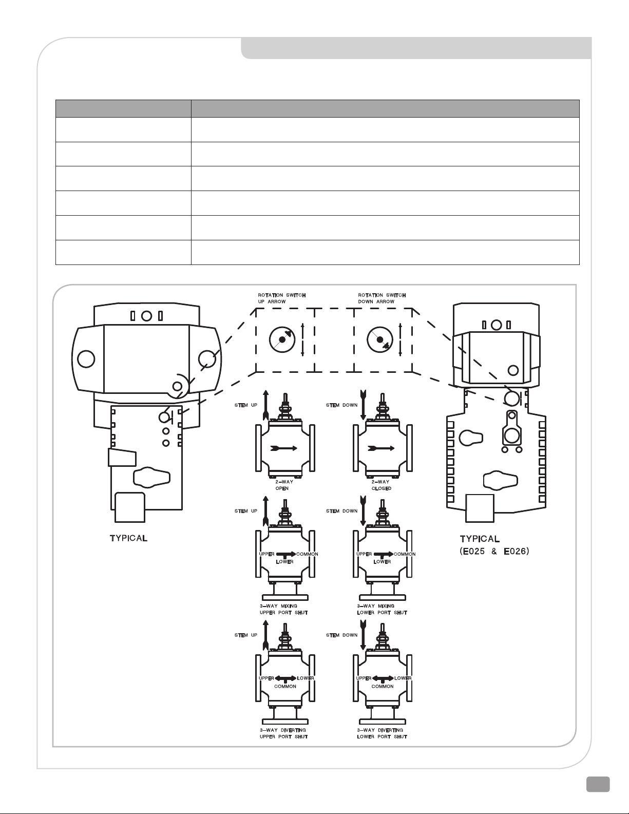
CONTROL ACTION - PROPORTIONAL CONTROL
E024, E025, E026, E029 & E030 Actuators - Rotation Switch position. How the valve and actuator react to the Control Signal. The
Fail-Safe position during Loss of Power and Loss of Signal are identical for an E024 and E029/E030 with VMS-35. For on-off control see
Addendum B on pages 21-25.
FACING DESCRIPTION
Up Arrow
(E024 and E029/E030)
Down Arrow
(E024 and E029/E030)
Up Arrow
(E024 and E029/E030 w/VMS-35)
Down Arrow
(E024 and E029/E030 with VMS-35)
Up Arrow
(E025 & E026)
Down Arrow
(E025 & E026)
Increasing Control Signal Closes, 2-way valves and Lower port for 3-way valve. Signal Failure Direction is Fail
Open (FO) 2-way valves and Fail Upper Port Closed for 3-way vales.
Decreasing Control Signal Closes, 2-way valves and Lower Port for 3-way valves. Signal Failure Direction is
Failed Closed (FC) for 2-way valves and Fail Lower Port Closed for 3-way valves.
Increasing Control Signal Closes, 2-way valves and Lower port for 3-way valve. Signal and Power Failure Direction is Fail Open (FO) 2-way valves and Fail Upper Port Closed for 3-way vales.
Decreasing Control Signal Closes, 2-way valves and Lower Port for 3-way valves. Signal and Power Failure
Direction is Fail Closed (FC) for 2-way valves and Fail Lower Port Closed for 3-way valves.
Increasing Control Signal Closes 2-way valves and Lower Port for 3-way valves. Signal Failure Direction is Fail
Open (FO) 2-way valves and Fail Upper Port Closed for 3-way valves.
Decreasing Control Signal Closes 2-way valves and Lower Port for 3-way valves. Signal Failure Direction is Fail
Closed (FC) for 2-way valves and Fail Lower Port Closed for 3-way valves.
(E024 and E029, E030)
HVAC_BAC_ELECTRIC_IOM_RevCa_0219
13
Page 14
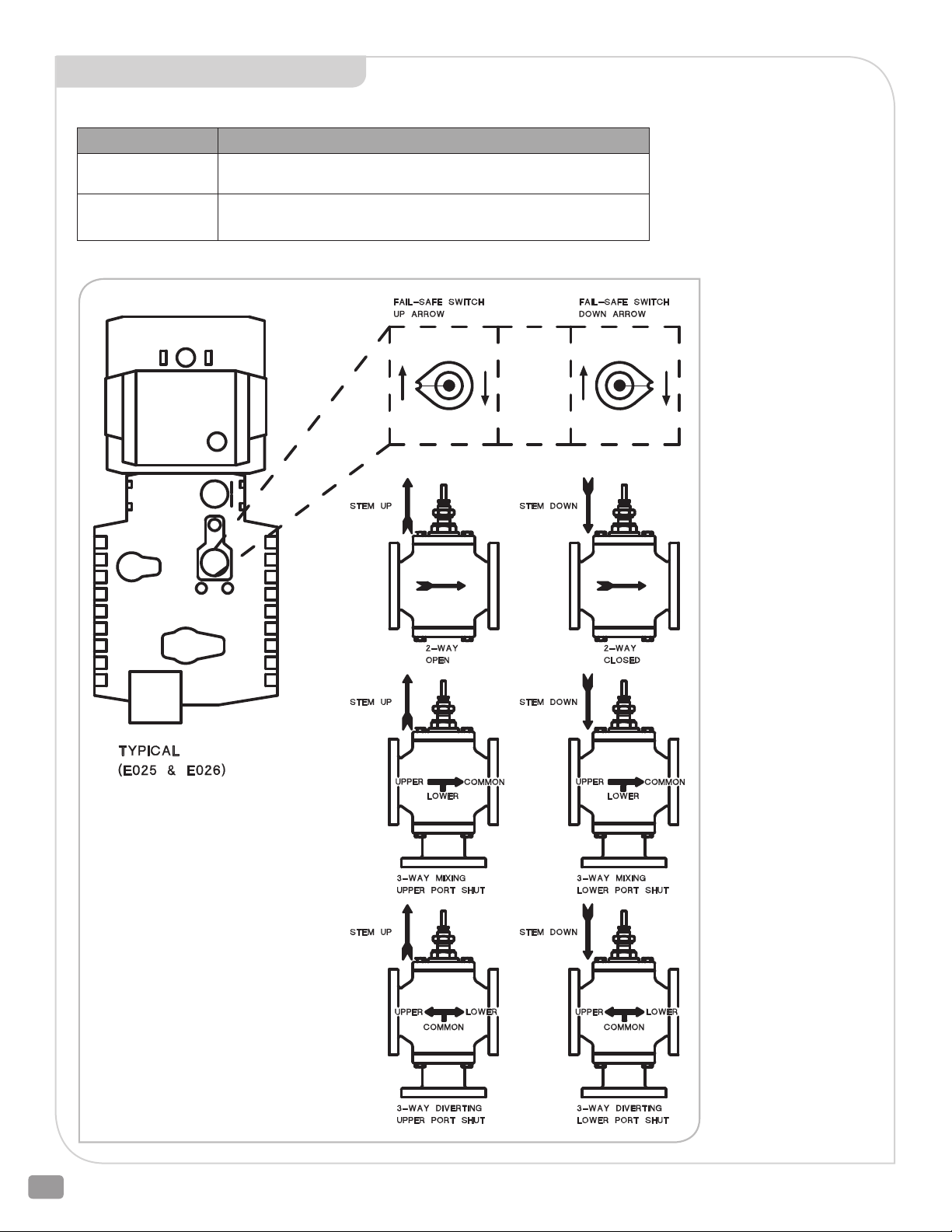
POWER FAILURE
E025 & E026 Actuators - Fail-Safe Switch position: Valve and actuator Power Failure Direction.
FACING
Up Arrow
(E025 & E026)
Down Arrow
(E025 & E026)
Switch must be fully in position shown or actuator will go to intermediate position on loss of power.
DESCRIPTION
Power Failure Direction is Fail Open (FO) 2-way valves and Upper Port
Closed for 3-way valves.
Power Failure Direction is Fail Closed (FC) for 2-way valves and Lower
Port Closed for 3-way valves.
2600 Emrick Blvd • Bethlehem, PA 18020 • USA • 800-922-0085 • www.warrencontrols.com
14
Page 15
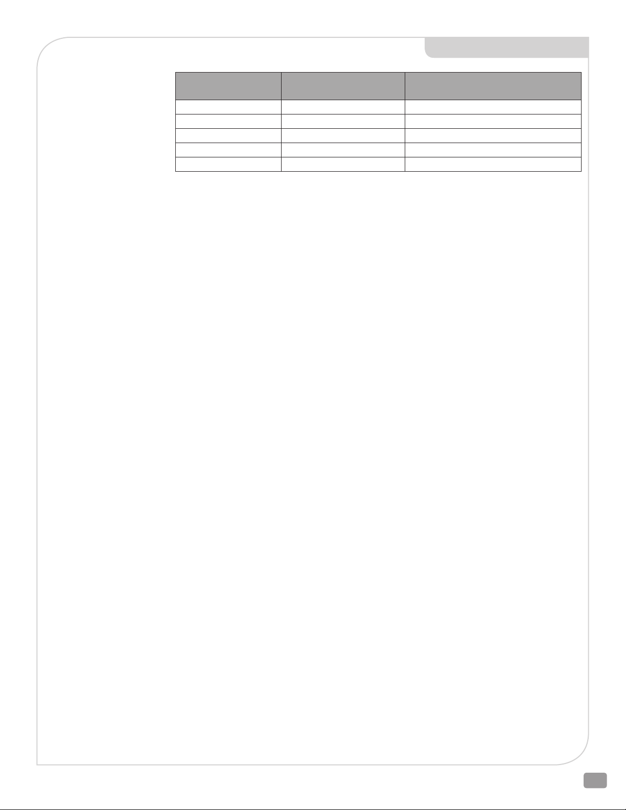
INDICATOR LIGHTS
STATUS
(yellow LED)
OFF ILLUMINATED Normal (no faults)
OFF BLINKING Power Failure is active ( E025 & E026 only)
ILLUMINATED OFF Fault is detected
OFF OFF No Power or Capacitors charging
ILLUMINATED ILLUMINATED Auto-Calibration is running
ADAPTION/ POWER
(green LED)
DESCRIPTION
1
NOTE:
1) Verify Control and Feedback Wiring
and Signals if a Fault is detected.
HVAC_BAC_ELECTRIC_IOM_RevCa_0219
15
Page 16
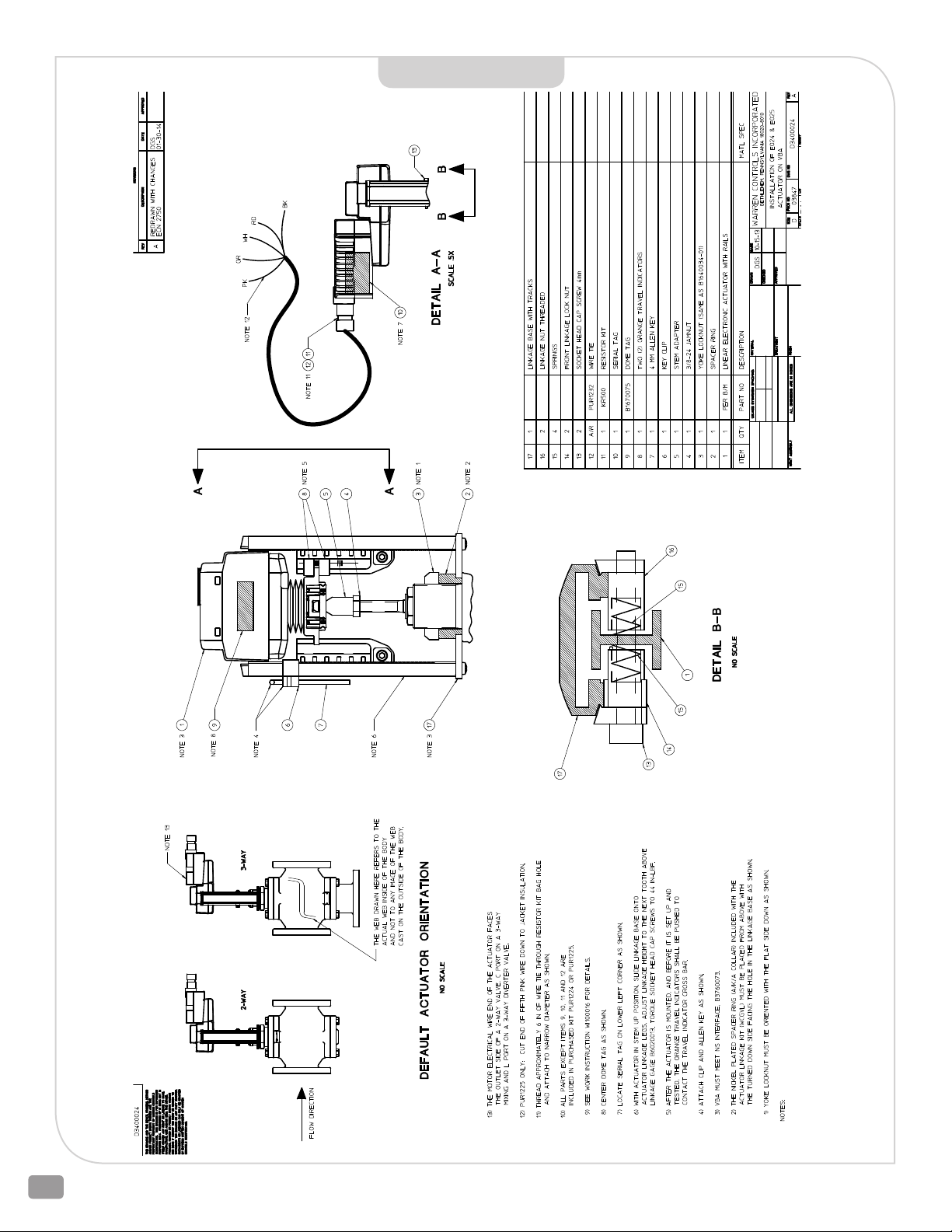
D3400024
2600 Emrick Blvd • Bethlehem, PA 18020 • USA • 800-922-0085 • www.warrencontrols.com
16
Page 17
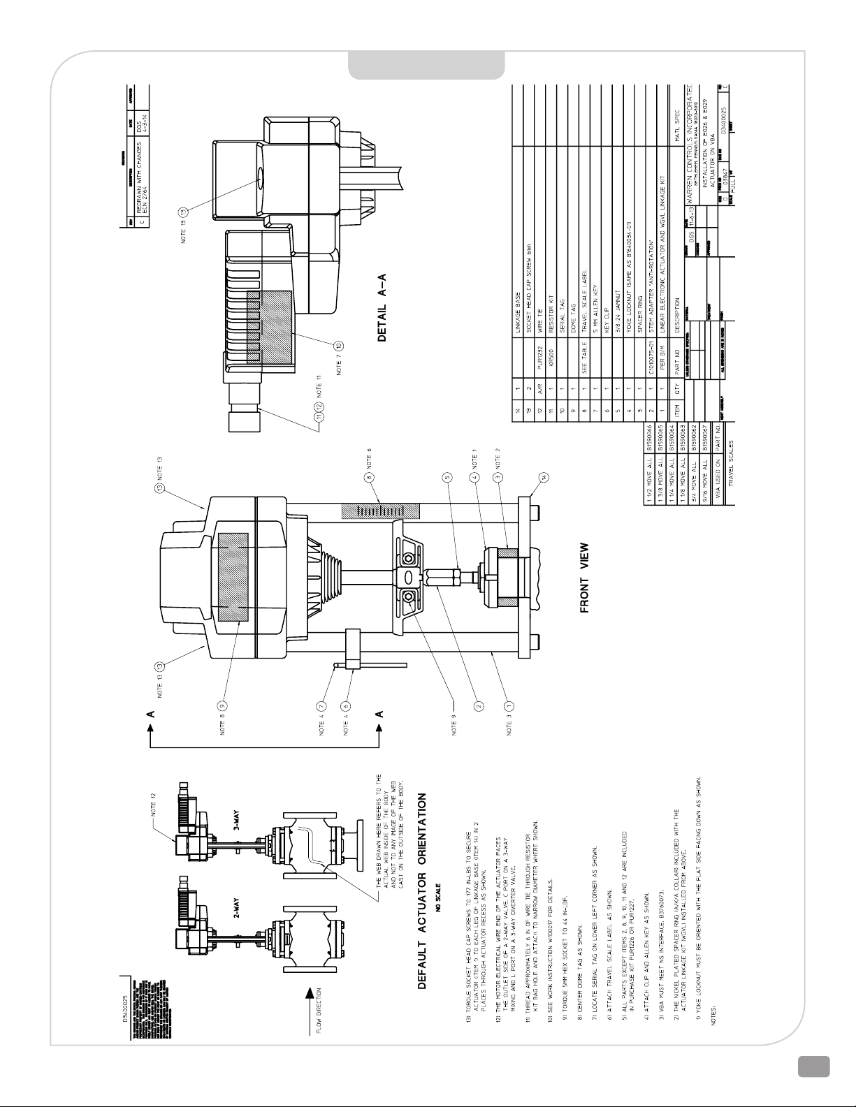
D3400025
HVAC_BAC_ELECTRIC_IOM_RevCa_0219
17
Page 18
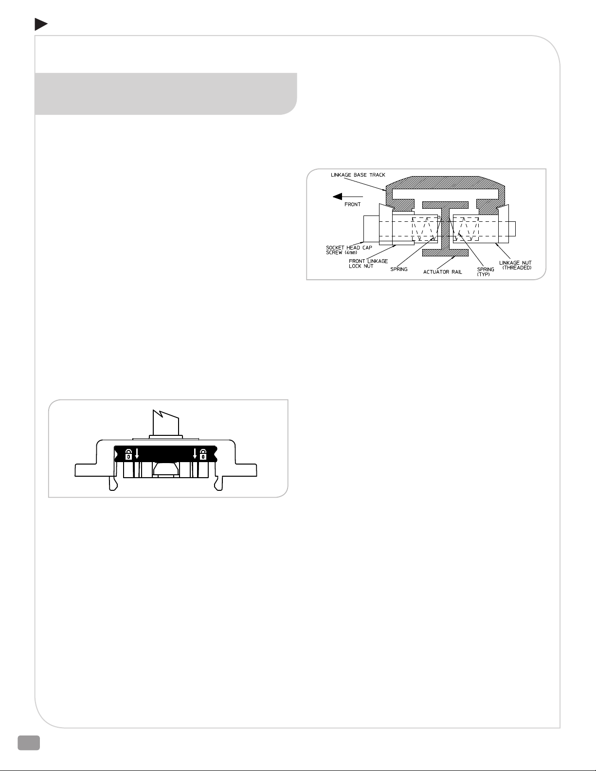
ADDENDUM A
READ ALL INSTRUCTIONS CAREFULLY BEFORE BEGINNING.
REMOVAL OF E024 & E025 ACTUATOR
AND LINKAGE BASE FROM VALVE
SEE DRAWING D3400024 on page 16
THESE INSTRUCTIONS SHOULD ONLY BE USED IF THE SOCKET HEAD
CAP SCREWS ITEM 13 HAVE BEEN LOOSENED AND THE POSITION OF
THE ACTUATOR ITEM 1 RELATIVE TO THE LINKAGE BASE ITEM 17 HAS
BEEN CHANGED. OTHERWISE USE THE REMOVAL AND INSTALLATION
INSTRUCTIONS ON PAGE 8 & 9.
1) Remove line pressure and isolate valve in piping.
2) Operate actuator (Item 1) so plug is off seat(s) or travel stop in
valve.
3) Remove power and signal from actuator. For E025, after
power is removed, cycle Fail-Safe Switch from Up Arrow to
Down Arrow until actuator stem no longer moves. Adaption/
Power (green LED) changes from blinking to off. Return FailSafe Switch to original position. If necessary use the manual
override to operate actuator so plug is off seat(s) or travel
stop in valve (See manual override on page 3).
WARNING: DO NOT FORCE OR TURN THE MANUAL
OVERRIDE WHEN THE MANUAL OVERRIDE
BUTTON IS NOT PRESSED. DOING SO MAY CAUSE
DAMAGE TO THE ACTUATOR GEARS.
6) Adjust the socket head cap screws (Item 13) so the teeth of
the front linkage lock nuts (Item 14) will not interfere with the
teeth of linkage base tracks (Item 17).
7) Press together the linkage base tracks and slide the actuator
rails out of the tracks until the actuator is separate from the
linkage base.
8) Thread the socket head cap screws out of the threaded
linkage nuts (Item 16). Remove and separate the threaded
linkage nuts and springs (Item 15).
9) Remove the socket head cap screws, front linkage lock nuts,
and springs together from the actuator rails. Separate the
socket head cap screws, front linkage nuts, and springs.
4) Unlock stem connector clamp, use fingers on the front and
back sides of black lock assembly to evenly raise the lock
assembly.
WARNING: WHEN HANDLING THE ACTUATOR TAKE
CARE NOT TO DAMAGE THE STEM CONNECTOR
CLAMP AND CROSS BAR ASSEMBLY.
5) Press the manual override button then use the actuator
manual override to raise the stem connector until the stem
adapter (Item 5) is disengaged (See manual override on page
3).
WARNING: DO NOT FORCE OR TURN THE MANUAL
OVERRIDE WHEN THE MANUAL OVERRIDE
BUTTON IS NOT PRESSED. DOING SO MAY CAUSE
DAMAGE TO THE ACTUATOR GEARS.
10) Remove the orange travel indicators (Item 8) from the
actuator rail.
11) Loosen yoke locknut (Item 3) until it is free of bonnet.
12) Remove spacer ring (Item 2).
13) Remove linkage base from valve.
14) Hold jam nut (Item 4) on valve stem and turn the stem adapter
(Item 5) to disengage from valve stem.
WARNING: THE VALVE STEM SHOULD NEVER BE
TURNED WHILE THE PLUG IS IN CONTACT WITH
THE SEAT OTHERWISE THE SEATING SURFACES
WILL BE DAMAGED VOIDING THE WARRANTY.
15) Remove stem adapter from valve stem.
16) Remove jam nut from valve stem.
2600 Emrick Blvd • Bethlehem, PA 18020 • USA • 800-922-0085 • www.warrencontrols.com
18
Page 19
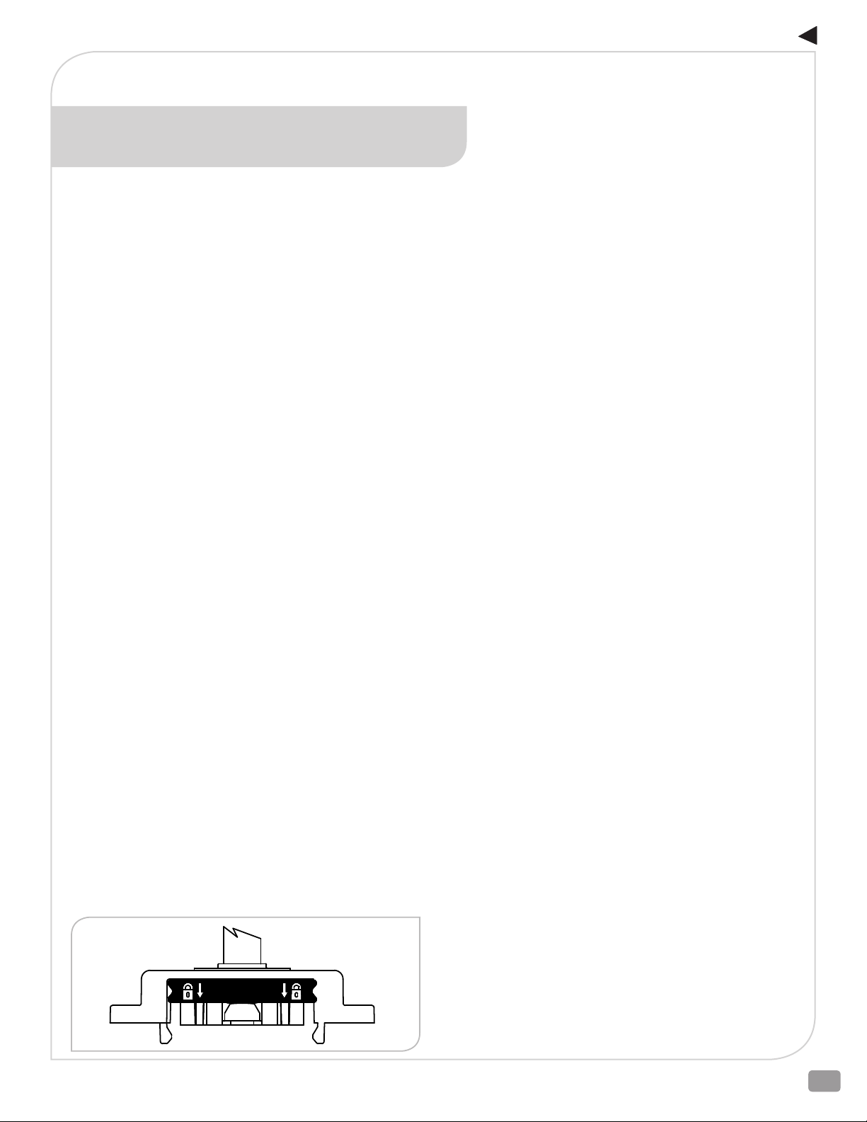
ADDENDUM A
READ ALL INSTRUCTIONS CAREFULLY BEFORE BEGINNING.
INSTALLATION OF E024 & E025 ACTUATOR
AND LINKAGE BASE ON A VALVE
SEE DRAWING D3400024 on page 16
THESE INSTRUCTIONS SHOULD ONLY BE USED IF THE SOCKET HEAD
CAP SCREWS ITEM 13 HAVE BEEN LOOSENED AND THE POSITION OF
THE ACTUATOR ITEM 1 RELATIVE TO THE LINKAGE BASE ITEM 17 HAS
BEEN CHANGED. OTHERWISE USE THE REMOVAL AND INSTALLATION
INSTRUCTIONS ON PAGE 8 & 9.
THE SILVER SPACER RING THAT COMES WITH THE ACTUATOR MUST BE
ASSEMBLED ON TOP SIDE OF YOKE WITH TURNED DOWN (MACHINED) SIDE
FACING DOWN AS SHOWN ON DRAWING D340024.
1) Push valve stem down until plug is seated. Note stem location.
2) Install hex jamnut (Item 4) on valve stem. Thread jamnut so
that one inch of threads are exposed between jamnut and
top of stem.
3) Hold jamnut on valve stem and turn the stem adapter (Item
5) until it bottoms out on the valve stem. Tighten jamnut to
the bottom of the stem adapter to secure valve stem to stem
adapter.
WARNING: THE VALVE STEM SHOULD NEVER BE
TURNED WHILE THE PLUG IS IN CONTACT WITH
THE SEAT OTHERWISE THE SEATING SURFACES
WILL BE DAMAGED VOIDING THE WARRANTY.
4) Place linkage base (Item 17), spacer ring (Item 2), and yoke
locknut (Item 3) over valve stem and onto bonnet. Watch
orientation of spacer ring and yoke locknut. Linkage base
must rest on bonnet.
5) Rotate linkage base to desired orientation. For the factory
default actuator position, when the actuator (Item 1) is
installed in the linkage base, the motor electrical wire end of
the actuator faces the outlet side of a 2-way valve, common
“C” port on a 3-way mixing, and lower “L” port on a 3-way
diverting valve. Thread yoke locknut onto bonnet and tighten
securely. Use a blunt chisel and hammer for final tightening.
6) Unlock stem connector clamp on the actuator, use fingers on
the front and back sides of black lock assembly to evenly raise
the lock assembly.
WARNING: WHEN HANDLING THE ACTUATOR TAKE
CARE NOT TO DAMAGE THE STEM CONNECTOR
CLAMP AND CROSS BAR ASSEMBLY.
7) Press the manual override button then use the actuator
manual override to lower the stem connector until a slight
resistance is felt. Then raise the stem connector approximately
2-1/4 turns of the manual override (approximately 0.086 inch)
(See manual override on page 3).
WARNING: DO NOT FORCE OR TURN THE MANUAL
OVERRIDE WHEN THE MANUAL OVERRIDE
BUTTON IS NOT PRESSED. DOING SO MAY CAUSE
DAMAGE TO THE ACTUATOR GEARS.
8) Insert first socket head cap screw (Item 13) through front
linkage lock nut (Item 14). Watch orientation. Install first
spring (Item 15) over threaded end of socket head cap screw
into spring bore of front linkage lock nut. Insert threaded end
of socket head cap screw into hole in socket for front linkage
lock nut in one of the actuator rails. The socket for the front
linkage lock nut is oriented away from the motor electrical
wire end of the actuator. Press front linkage lock nut into
socket. The teeth on the front linkage lock nut must face the
teeth on the closest linkage base track when the actuator
is installed on the linkage base. Install second spring on
exposed threaded end of the socket head cap screw. Install
threaded linkage nut (Item 16) over threaded end of socket
head cap screw so second spring is captured in spring bore
of threaded linkage nut. The dovetail on the threaded linkage
nut must face the groove in the closest linkage base track
when the actuator is installed on the linkage base. Thread the
socket head cap screw into the threaded linkage nut. Adjust
the socket head cap screw so the teeth of the front linkage
lock nut will not interfere with the teeth of linkage base track
when the actuator is installed in the linkage base in the next
step. Repeat this step with second socket head cap screw
9) Verify the valve stem is down and the plug is seated. Refer to
location noted in Step 1. Position the actuator (Item 1) in the
desired orientation. For the factory default actuator position,
the motor electrical wire end of the actuator faces the outlet
side of a 2-way valve, common “C” port on a 3-way mixing
valve, and lower “L” port on a 3-way diverting valve. Verify that
the teeth of both front linkage lock nuts will face the teeth in
the closest linkage base track when the actuator is installed
in the linkage base. Verify that the dovetail of both threaded
linkage nuts will face the groove in the closest linkage base
track when the actuator is installed in the linkage base. Press
together the linkage base tracks and insert the actuator rails
into the tracks. Slide the actuator rails into the actuator base
tracks until the metal actuator stem touches the top of the
stem adapter.
HVAC_BAC_ELECTRIC_IOM_RevCa_0219
19
Page 20
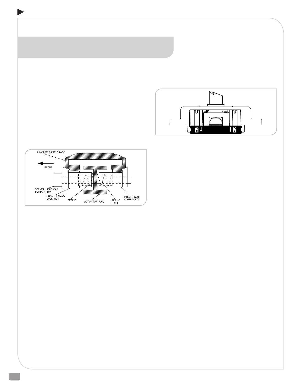
ADDENDUM A
READ ALL INSTRUCTIONS CAREFULLY BEFORE BEGINNING.
INSTALLATION OF E024 & E025 ACTUATOR
AND LINKAGE BASE ON A VALVE CONTINUED
10) Press the first threaded linkage nut into the socket on the
actuator rail and hold. The dovetail on the threaded linkage
nut must fully engage the groove on the linkage base track.
Press the front linkage lock nut into the socket on the actuator
rail and hold. The teeth on the front linkage lock nut must
engage the lowest teeth possible on the linkage base track.
The dovetail on the front linkage lock nut must fully engage
the groove on the linkage base track. Tighten the socket
head cap screw hand tight. Repeat for the second threaded
linkage nut. The number of teeth visible on the linkage base
tracks below the front linkage lock nuts should be the same
on both sides. If the number of teeth visible on the linkage
base tracks below the front linkage lock nuts is not the same
on both sides, loosen the socket head cap screws then repeat
this step.
13) Lock stem connector clamp, use fingers on the front and
14) Install orange travel indicators (Item 8) on embossed actuator
back sides of black lock assembly to evenly lower the lock
assembly.
WARNING: WHEN HANDLING THE ACTUATOR TAKE
CARE NOT TO DAMAGE THE STEM CONNECTOR
CLAMP AND CROSS BAR ASSEMBLY.
rail above and below travel indicator cross bar. Push orange
travel indicators on leg of actuator to contact cross bar.
11) Tighten both 4 mm socket head cap screws to 44 in-lbf torque.
12) Use actuator manual override to verify the metal actuator
stem touches the top of the stem adapter (See manual
override on page 3).
WARNING: DO NOT FORCE OR TURN THE MANUAL
OVERRIDE WHEN THE MANUAL OVERRIDE
BUTTON IS NOT PRESSED. DOING SO MAY CAUSE
DAMAGE TO THE ACTUATOR GEARS.
15) Connect power and signal to actuator. (See also Set-Up on
page 12)
16) Press the Adaption (Auto Calibration) button on the actuator
and wait until the cycle is complete.
17) Stroke valve several times to check operation.
18) Return line pressure to valve.
2600 Emrick Blvd • Bethlehem, PA 18020 • USA • 800-922-0085 • www.warrencontrols.com
20
Page 21
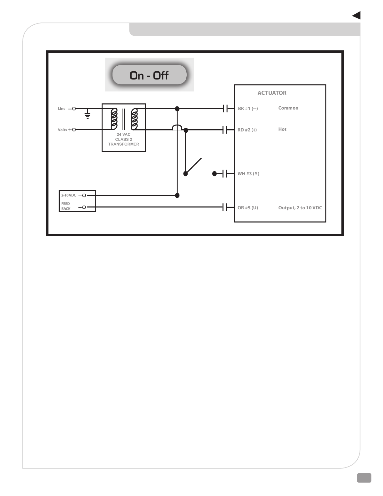
ADDENDUM B
On - Off
Line
Volts
24 VAC
CLASS 2
TRANSFORMER
2-10 VDC
FEED-
BACK
ACTUATOR
BK #1 ( )
RD #2 ( )
WH #3 (Y)
OR #5 (U)
Common
Hot
Output, 2 to 10 VDC
ACTUATOR WIRING DIAGRAM ON-OFF CONTROL
HVAC_BAC_ELECTRIC_IOM_RevCa_0219
21
Page 22
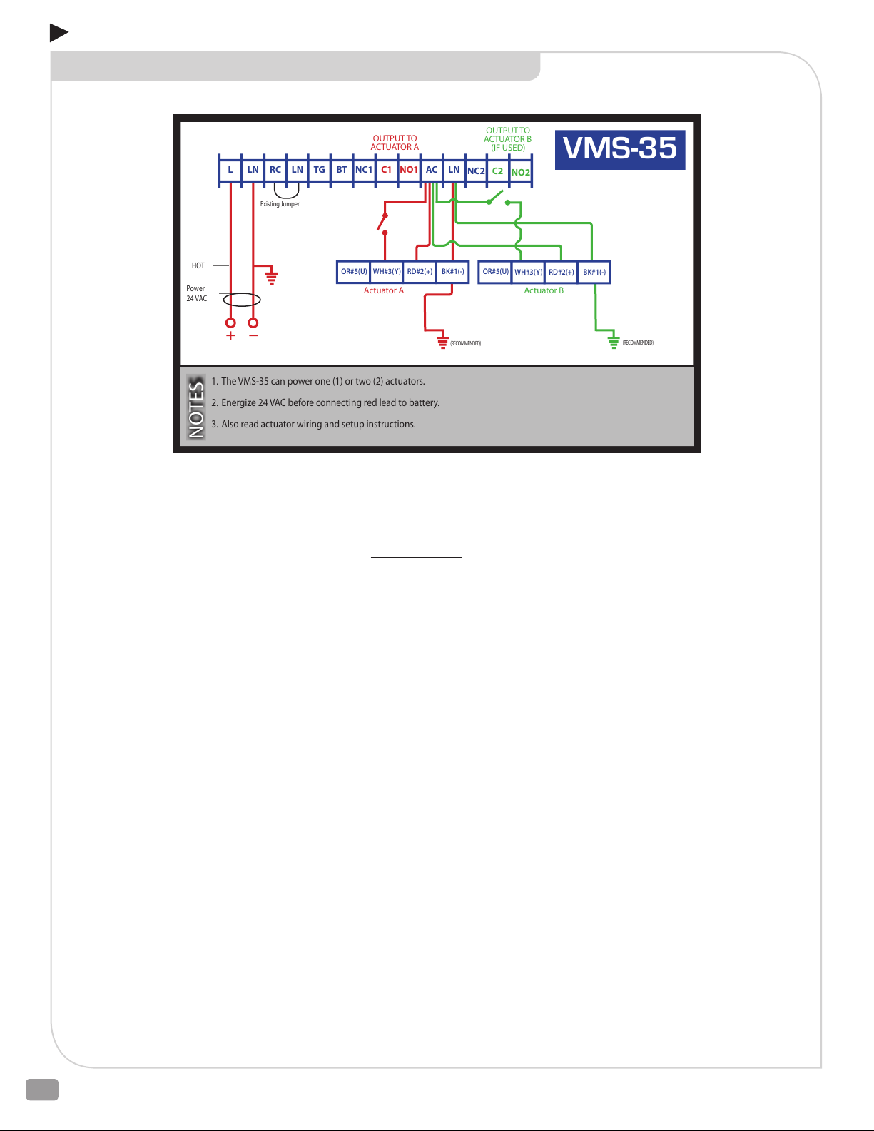
Power
24 VAC
HOT
Existing Jumper
L LN RC LN TG BT AC LNNC1 C1 NO1
NC2 C2
NO2
(RECOMMENDED)
(RECOMMENDED)
OUTPUT TO
ACTUATOR A
OUTPUT TO
ACTUATOR B
(IF USED)
Actuator BActuator A
1. The VMS-35 can power one (1) or two (2) actuators.
2. Energize 24 VAC before connecting red lead to battery.
3. Also read actuator wiring and setup instructions.
NOTES
VMS-35
OR#5(U)
WH#3(Y) RD#2(+) BK#1(-)
OR#5(U)
WH#3(Y) RD#2(+) BK#1(-)
ADDENDUM B
VMS-35 WIRING DIAGRAM ON-OFF CONTROL
TERMINALS
L System Power 24 VAC (+)
LN System Neutral (-)
RC Remote Control
BT Battery Test (+)
TG Test Ground (-)
C1 Not Used
C2 Not Used
NC1 Not Used
NC2 Not Used
NO1 Not Used
NO2 Not Used
AC 24 VAC Out (+)
Operation:
On - Off Normal: Terminal L is connected to 24 VAC building power.
Terminal LN completes the circuit to BK. Actuator responds to opening
and closing of contact between WH# 3(Y) and Terminal AC.
Power Failure: Terminal AC changes to 24 V square wave from battery/
inverter. Actuator responds to position of contact between WH#3 (Y)
and Terminal AC.
2600 Emrick Blvd • Bethlehem, PA 18020 • USA • 800-922-0085 • www.warrencontrols.com
22
Page 23

ADDENDUM B
INSTALLATION ON-OFF CONTROL
1. Disengage the 24 VAC building power circuit before wiring. Verify that the battery inside the VMS-35 has its wires disconnected
and leave them that way. Disconnect them if they are connected.
2. Connect the VMS-35 to the actuators as shown. The VMS-35 can power one or two actuators.
Actuator A: Connect terminal AC to red wire from actuator to provide power. Connect grounded reference – negative/black wire
from actuator to terminal LN. Connect terminal AC to white wire from actuator to drive the valve stem to the rotation switch position.
Disconnect terminal AC from white wire from actuator to drive the valve stem to the opposite position.
Actuator B: Connect terminal AC to red wire from actuator to provide power. Connect grounded reference – negative/black wire
from actuator to terminal LN. Connect terminal AC to white wire from actuator to drive the valve stem to the rotation switch position.
Disconnect terminal AC from white wire from actuator to drive the valve stem to the opposite position.
3. While still disconnected, wire the VMS-35 to 24 volts AC power. Connect the hot to terminal L then then neutral to terminal LN.
4. Engage the 24 VAC building power.
5. Verify that building power is live then connect the loose red wire inside the VMS-35 enclosure to the positive (+) battery terminal
and the black wire to the negative (-) battery terminal.
NOTE: Engage the 24 VAC power to the VMS-35 before connecting the battery. Connecting the battery rst causes the VMS-35 to
go into the power failure mode. If there are conditions other than power failure during which the actuator should be driven to the
rotation switch position, replace the jumper between LN & RC with a contact that opens on demand.
HVAC_BAC_ELECTRIC_IOM_RevCa_0219
23
Page 24
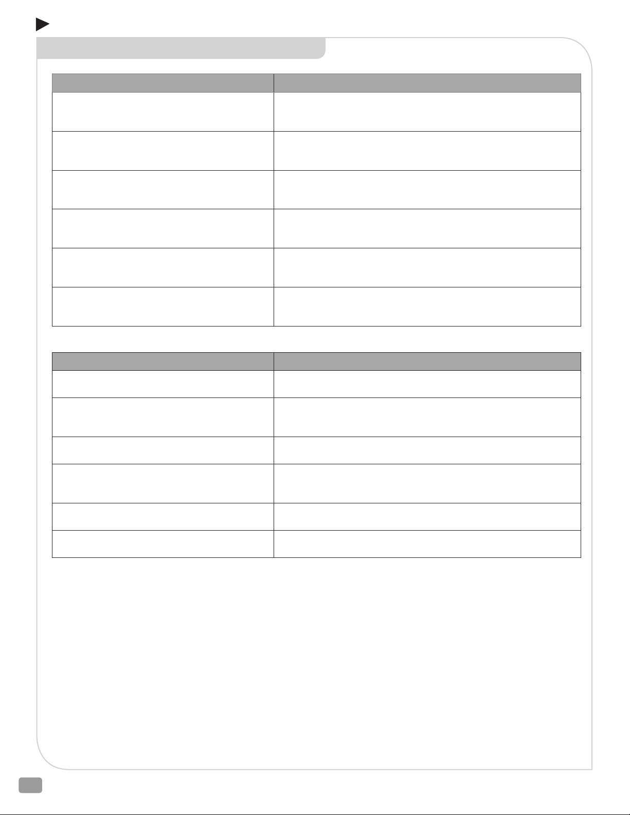
ADDENDUM B
CONTROL ACTION ON-OFF CONTROL
Rotation Switch Position On-O Control Action
Facing Up Arrow
(E024 & E029 without VMS-35)
Facing Up Arrow
(E024 and E029/30 with VMS-35)
Facing Down Arrow
(E024 & E029 without VMS-35)
Facing Down Arrow
(E024 and E029/30 with VMS-35)
Facing Up Arrow
(E025 & E026)
Facing Down Arrow
(E025 & E026)
WH#3(Y) connected to RD#2(+) Closes 2-way valves and Closes Lower
port 3-way valves. WH#3(Y) not connected to RD#2(+) Opens 2-way
valves and Closes Upper port 3-way valves.
WH#3(Y) connected to Terminal AC Closes 2-way valves and Closes Lower
port 3-way valves. WH#3(Y) not connected to Terminal AC Opens 2-way
valves and Closes Upper port 3-way valves.
WH#3(Y) connected to RD#2(+) Opens 2-way valves and Closes Upper
port 3-way valves. WH#3(Y) not connected to RD#2(+) Closes 2-way
valves and Closes Lower port 3-way valves.
WH#3(Y) connected to Terminal AC Opens 2-way valves and Closes Upper
port 3-way valves. WH#3(Y) not connected to Terminal AC Closes 2-way
valves and Closes Lower port 3-way valves.
WH#3(Y) connected to RD#2(+) Closes 2-way valves and Closes Lower
port 3-way valves. WH#3(Y) not connected to RD#2(+) Opens 2-way
valves and Closes Upper port 3-way valves.
WH#3(Y) connected to RD#2(+) Opens 2-way valves and Closes Upper
port 3-way valves. WH#3(Y) not connected to RD#2(+) Closes 2-way
valves and Closes Lower port 3-way valves.
Rotation Switch Position On-O Power Failure Action
Facing Up Arrow
(E024 & E029 without VMS-35)
Facing Up Arrow
(E024 and E029/30 with VMS-35)
Facing Down Arrow
(E024 & E029 without VMS-35)
Facing Down Arrow
(E024 and E029/30 with VMS-35)
Facing Up Arrow
(E025 & E026)
Facing Down Arrow
(E025 & E026)
LAST POSITION
WH#3(Y) connected to Terminal AC Closes 2-way valves and Closes Lower
port 3-way valves. WH#3(Y) not connected to Terminal AC Opens 2-way
valves and Closes Upper port 3-way valves.
LAST POSITION
WH#3(Y) connected to Terminal AC Opens 2-way valves and Closes Upper
port 3-way valves. WH#3(Y) not connected to Terminal AC Closes 2-way
valves and Closes Lower port 3-way valves.
See POWER FAILURE E025 & E026 actuators – Fail-Safe Switch position PG
14
See POWER FAILURE E025 & E026 actuators – Fail-Safe Switch position PG
14
2600 Emrick Blvd • Bethlehem, PA 18020 • USA • 800-922-0085 • www.warrencontrols.com
24
Page 25
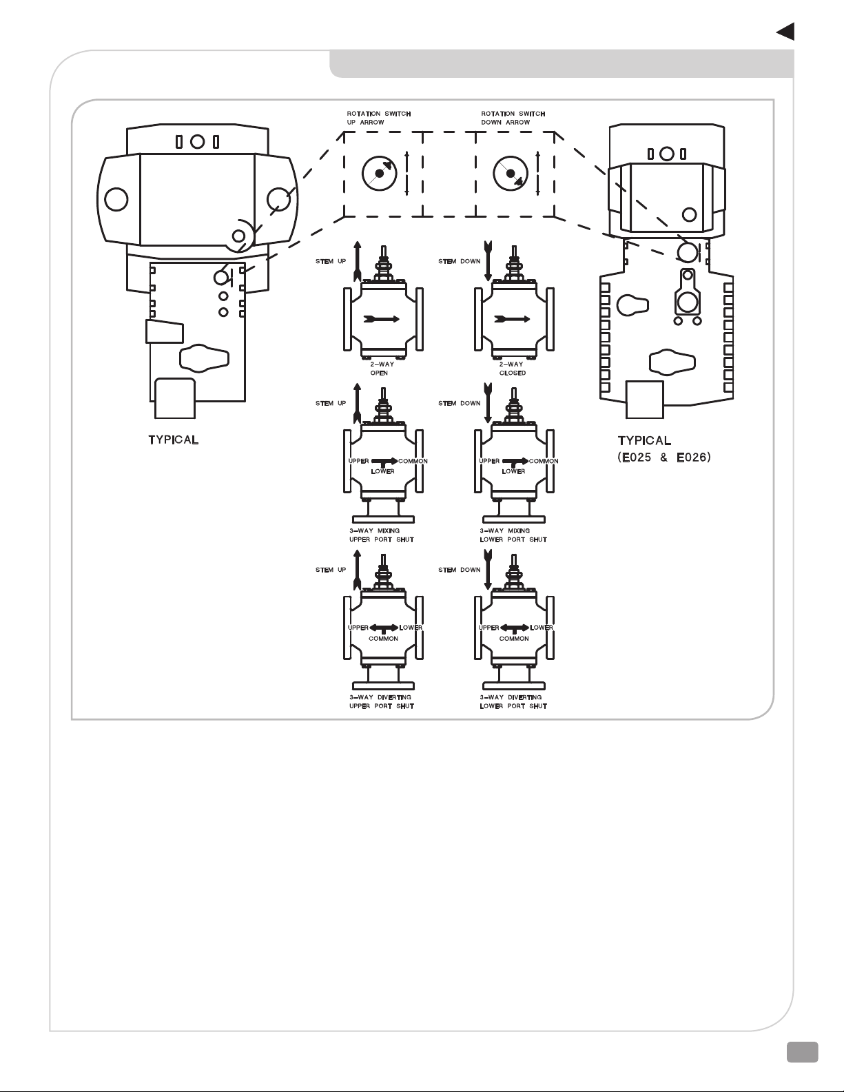
ADDENDUM B
CONTROL ACTION ON-OFF CONTROL
(E024 and E029, E030)
HVAC_BAC_ELECTRIC_IOM_RevCa_0219
25
Page 26

NOTES
2600 Emrick Blvd • Bethlehem, PA 18020 • USA • 800-922-0085 • www.warrencontrols.com
26
Page 27

NOTES
HVAC_BAC_ELECTRIC_IOM_RevCa_0219
27
Page 28

HVAC_BAC_ELECTRIC_IOM_RevCa_0219
2600 EMRICK BLVD • BETHLEHEM, PA 18020 • USA •8009220085 • WWW.WARRENCONTROLS.COM
DEPENDABLE, RUGGED, PRECISION CONTROL VALVES AND ACCESSORIES
 Loading...