

Page 1

DC INVERTER AIR PLASMA
CUTTING MACHINE
LGK-40
Instruction Manual
M/s WARPP ENGINEERS PVT. LTD.
B-1005, WESTERN EDGE II, NEAR METRO MALL,
OFF.WESTERN EXPRESS HIGHWAY, BORIVALI (E),
MUMBAI-400 066.
Tel:91-22-28542272/73/74. Fax: 91-22-28542275.
Email:sales@warpp.co.in W ebsite:www.warpp.co.in
Page 2

Introduction
The cutting machine applies the advanced technology of inversion. Its
principle is making the 50/60Hz line frequency inverted to high frequency
(more than 100 kHz) with the V-MOSFET high power binistor, and then
stepping down and rectifying to attain high power DC source through the
pulse width modulation (PWM) technology. Thus the weight and size of the
transformer is greatly decreased and the efficiency is improved up 30%. The
principle of high frequency oscillation (HFO) is applied in the arc striking
system and makes it easy to arcing. Furthermore, the gas pre-flow and
post-flow function is available. It is stable, reliable, portable, energy saving,
noiseless, fast cutting speed, smooth scarfing and free of burnishing.
The cutting machine can be widely used. It can cut stainless steel, low carbon
steel, copper and other non-ferrous metals. The conversion efficiency of the
whole machine is over 85%.
Page 3

CONTENTS
1. MAJOR TECHNICAL PARAMETERS ................................................................... ................ 1
2. INSTALLATION ......................................................................................................................... 2
3. OPERATION ............................................................................................................................... 3
4. PRECAUTIONS .......................................................................................................................... 4
5. MAINTENANCE ........................................................................................................................ 6
6. TROUBLESHOOTING ............................................................................................................. 7
Page 4
r
r
1. Major Technical Parameters
Model
LGK-40
Parameters
Input voltage(V) AC220V±10%
Input power supply capacity
(KVA)
6
No-load voltage(V) 230
Current adjustable range(A) 10-40
Rated output voltage(V) 100
Rated duty cycle(%) 60
Efficiency ≥ 85
Power factor cosø 0.93
Insulation level B
Casing protection level IP21
Arcing mode contacted
Recommended air compresso
pressure(KG)
Recommended air compresso
air displacement(KG)
4.5
0.17
Net weight(kg) 8
Dimensions(mm)
( L×W×H )
375×155×240
Page 5

2. Installation
2.1.Connection of the input lines
1. Every cutting machine is equipped with a power line, which should be
connected to appropriate voltage level. Some users directly connect the
220V power source to the 380V AC power supply due to carelessness and
make the components inside the machine burnt.
2. The power line should be well connected to the power switch or the
connector and prevented from oxidization. If possible, check if the power
voltage lies in the range percent with instruments.
2.2.Connection of the output lines
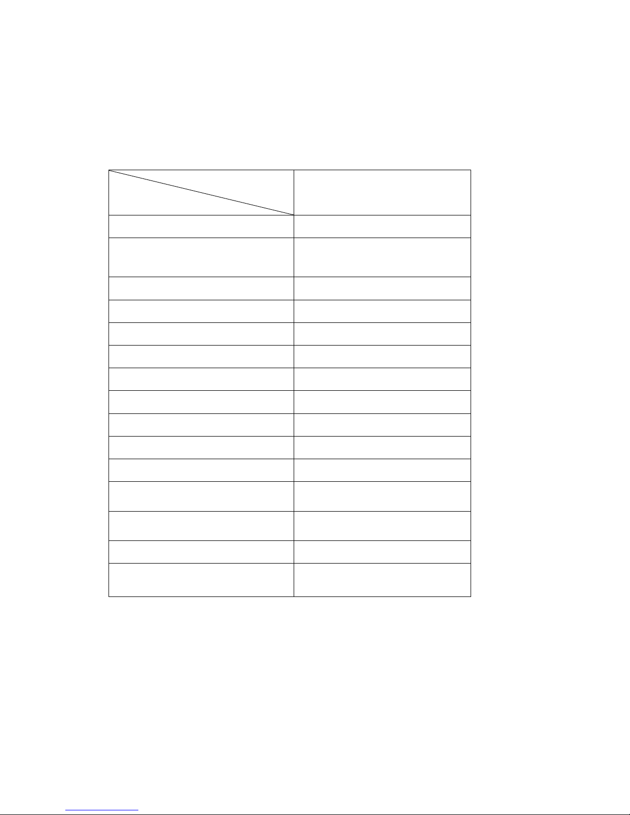
power source abnormity indicator cutting current knob
integrated electro-gas output cutting torch output terminal
A
terminal to cutting torch switch connector to workpiece
Figure 1. Control panel of LGK-40
Page 6

1. Connect the output terminal of the compressor and the input terminal (IN) of
the pressure reducing valve with a gas pipe; there should be closed butt
joint between the output terminal (OUT) and the copper tube on the back of
the machine.
2. Connect the copper nut on the cutting torch with the integrated electro-gas
output terminal and clockwise rotate it (to avoid air leakage). The fast plug
on the ground cable should be connected to the positive output terminal on
the front panel of the cutting machine and tightened up.
3. Connect the switch plug on the cutting torch with the cutting torch switch
connector on the panel.
4. Rotate the electrodes into the cutting torch in proper order. Tighten them
when they reach the end. Then correctly install the spray nozzle and the
shielding case onto the designated positions successively. (Attention: the
machine should be turned down each time the spray nozzle or the electrode
is replaced or examined.)
2.3.Examination
1. Whether the cutting machine is grounded according to the standard.
2. Whether all the connection points is well contacted.
3. Whether the voltage that the power line is connected to is correct.
4. Whether there is no abrasion, breakage or bending on the connection cable
and the gas pipe.
3. Operation
1. Turn on the power switch on the front panel and keep it to “ON”. This time
the power LED shines and the screen of the gauge outfit displays the preset
current value.
2. Rotate the air pressure knob to the value you want. Open the valve of the
compressed air.
3. Press down the control button on the cutting torch and the electromagnetic
valve acts. The discharging sound of high frequency arc striking from inside
the machine can be heard, and at the same time, gas flows out from the
spray nozzle of the cutting torch.
4. Preset the corresponding cutting current according to the thickness of the
workpiece to be cut.
Page 7

5. Contact the copper nozzle of the cutting torch with the workpiece (if the
copper nozzle carries with pilot arc, the distance between the nozzle and the
workpiece is approximately 2mm), and press down the button on the cutting
torch to ignite arc. Properly raise the cutting torch, making it about 1mm
from the workpiece, and then cutting can be started.
4. Precautions
4.1.Operating environment
• Use the machine in relatively dry air (humidity≤80%).
• The ambient temperature should lie between -10°C and +40°C.
• Avoid using the machine in direct sunlight or in the rain.
• Avoid using the machine in environments that is dusty or filled with
corrosive gas.
4.2.Summary for safety items
1. Keep good ventilation
The size of the machine is relatively small with compact structures, and the
output current is heavy. The natural ventilation condition cannot meet the heat
radiation requirements of the components, so an axial flow fan is installed inside
the machine for forced cooling.
NOTE: Do not cover or block the louver for ventilation on both sides and on the
front of the machine. The place that the welding machine is installed should at
least 0.3m from the surrounding objects. The ventilation condition should be
ensured to be ceaselessly improved. This is extremely important for the failure
free operation and service life of the welding machine.
2. By all means avoid overload
Overload operation is strictly forbidden. Otherwise sudden ceasing operation will
emerge during the cutting process. This is because the thermosensitive element
inside the cutting machine functions when it works at an overload. The primary
power source does not need to be cut off. Let the fan continue working to
quicken the cooling down process. The operation can be resumed when the
temperature drops to the tolerance range.
3. By all means avoid overvoltage
Consult the table of “major technical parameters” for the range of the power
supply voltage range of the cutting machine. In this case, the automatic
compensation circuit in the machine can ensure that the welding current does
not exceed the permitted level. If the supply voltage exceeds the specified value,
the components will be damaged, so please be twice as careful.
Page 8

4. There is a ground terminal on the back of each welding machine, whose
symbol is the earthing mark. Before working starts, connect the casing of the
machine with the ground with a wire whose sectional area is 10mm
2
to avoid
static electricity or electric leakage that can cause failure.
5. During working, do not touch the output terminal with bare hands to avoid
electric shock.
4.3.Matters needing attention during cutting
1. Hold the cutting torch with your hands and press the switch when you are
preparing to cut. If this moment there is plasma arc blowing out from the
nozzle bore, the electrode and the nozzle are correctly installed. If no
plasma or only weak plasma arc blows out from the nozzle bore, the
electrode and the nozzle are incorrectly installed and need reinstalling after
the machine is turned off.
2. The external rim of the nozzle bore should aim at the edge of the workpiece
when cutting begins. Press the switch of the cutting torch to strike arc. If the
arc is not stricken, release the switch and press it again. After the arc is
successfully stricken, move the cutting torch at a uniform speed to conduct
normal cutting (The speed varies according to the thickness of the plate. If
the sparks upwell, it indicates that the moving speed is too high and the
workpiece is not cut to full depth so that the moving speed should be
adjusted).
3. The cutting speed should be slowed down when cutting comes to the end
and the workpiece is about to be broken. Release the switch of the cutting
torch and cutting is finished.
4. If splashing matters adhere to the surface of the nozzle and affect the
cooling result, they should be cleaned without delay. In addition, the dust
and splashing matters on the head of the cutting torch should be often
cleaned so that the effect of heat elimination can be kept.
5. The wheel carrier of the cutting torch is for the purpose of keeping the
distance between the end face of the nozzle and the plate. It is strictly
forbidden to dismount the wheel carrier of the cutting torch. Otherwise the
distance between the end face of the nozzle and the plate cannot be
ensured and may cause the nozzle to contact the plate to burn the cutting
torch.
6. Replacement of the electrode and the nozzle
Page 9

The electrode and nozzle should be replaced when:
(1) The consumption depth of the hafnium wire of the electrode is over 1.5mm;
(2) The diameter of aperture of the nozzle is irregularly out of shape;
(3) The cutting speed obviously slows down and green flare emerges in the arc;
(4) It is hard to strike arc;
(5) The cut is skew or widen.
The electrode and the nozzle should be simultaneously replaced without delay;
otherwise strong arc will emerge inside the nozzle and break down the electrode
and the nozzle or even burn the cutting torch out. The nozzles are different if the
models are different so that the model uniformity should be kept when the
nozzle is replaced.
7. During cutting, the cable line should be kept as fully as possible. Even if the
space is too limited, dog leg should be avoided. Do not step on or extrude
the cable line in order to avoid gas suffocate and gas inadequacy that may
burn the cutting torch out. The cable line should be prevented from
contacting with sharp things so as to avoid breakage.
8. Dismount the nozzle casing, the nozzle, the electrode and the pilot arc line
(if the pilot arc line is not removed the cutting torch will be burned out).
Press down the switch after the machine is started up and this moment there
is gas blowing out from the hole of the air injector to clean the soil inside the
air injector. It should be cleaned once every day after used, which lasts
about 15s each time.
9. The head of the cutting torch should not be used as a knocking tool.
5. Maintenance
1. Periodically get rid of the dust with dry and clean compress air. If the welding
machine is used in environments with heavy smoke and serious polluted air,
dust elimination should be conducted at least once a month.
2. The pressure of the compressed air should be adjusted down to the value
required to prevent from damaging the small components in the machine.
3. Examine whether the electrical continuity places are well contacted
(especially the socket connectors). Reinforce the loosen connection points.
If there are oxidation phenomena, erase the oxide film with sandpaper and
reconnect them.
Page 10

4. Prevent the machine from water entering or being affected with damp,
otherwise dry it by blowing and examine the insulation condition with a
megohmmeter (both between the connected nodes and the between the
connection points and the casing). Welding cannot be continued unless no
abnormal circumstance is found.
5. If the welding machine will be disused for a long time, it should be put into
the original packaging and stored in a dry environment.
6. Troubleshooting
Note: The following operation requires that the operator have enough
professional knowledge on electricity and overall elementary knowledge of
safety. The operation should have the qualification certificate that can
prove his ability and knowledge.
Troubleshooting for LGK-40:
Faults Correction actions
The power LED shines
The fan does not rotate and the
control button is out of control.
The power LED shines.
The fan rotates. If the control
button of the cutting torch is
pressed, the electromagnetic
valve acts without the sound of
high frequency arc striking
discharging, and the red LED
inside the machine shines.
The power LED shines.
The fan rotates. If the control
button of the cutting torch is
pressed, the electromagnetically
operated valve acts without the
sound of high frequency arc
striking discharging, and the red
LED inside the machine does not
shine.
Overvoltage protection. Turn off the machine and wait for a
moment. Then restart the machine.
1. The MOS field effect tube K1170 of the upper board is
damaged (the driving module is damaged).
2. The step up electric transducer is damaged.
3. The control module is damaged.
There is something wrong with the arc striking part:
1. The distance of the discharging nozzle may be too long or
there may be edge adherence phenomenon.
2. There may be the phenomenon of open circuit or loose
contact in the primary coil of the arc striking transformer.
3. The quadruple voltage rectifier diode may be sparked
over.
4. The high frequency capacitor 102/10KV may leak
electricity.
5. The relay may be damaged.
Arc cannot be stricken during
welding, and the else is normal.
1. The input voltage is too low.
2. The pressure of the air compressor is too high or too low.
Page 11

 Loading...