

Page 1

-1-
INTIG- PULSE
Digital Inverter
MMA/TIG / Pulse TIG
Welding Machines
Operating manual
WARPP ENGINEERS PVT. LTD.
B-1005, 10TH FLOOR, WESTERN EDGE II, NEAR METRO MALL,
OFF.WESTERN EXPRESS HIGHWA Y, BORIVALI (E,)
MUMBAI-400 063.
TEL: 91-22-28542272 /73/74 / 32404434 Fax91-22-28542275.
E-mail:[email protected] Web Site: www.warpp.co.in
Page 2

-2-
Thank you for selecting WARPP brand inverter welding machine. In order to keep
THE operator safe, away from unexpected accidents, and enjoy full benefits offered by
our quality products during welding, please read the instruction in details prior to
operation. Complying with procedures defined in this manual is always appreciated.
INDEX
1. Usage& Features……………………………………..…(3)
2. Safety Precautions………………………………………(3)
3. Installation…………….………………………………...(5)
4. Principle in Brief…………….………………………....(7)
5. Operating Instruction…………………………………..(8)
6. Repair& Maintenance.………………………….…….(14)
7. Technical Data………………………………………..(16)
8. Appendix A: Ordinary failures, probable cause &
countermeasures……………………(17)
9. Structural Diagram……………………………………….(18)
10. Spare Part List………………………………………….(24)
Page 3

-3-
Usage & Features
IN TIG series pulse TIG welders include 315 A, and 400A types, can
Perform DC TIG, Pulse TIG, and DC MMA, used for mild steel, alloy
steel, stainless steel, Copper, Silver, and Titanium welding. This series
welder enjoy reasonable static characteristic and sound dynamic
characteristic as well as comprehensive functions:
& Soft switch Inverter, high efficiency and reliability, small size,
light weight and portable
& Non-source power factor correcting technical, high PF(power
factor)
& Multifunction, convenience, good adjustability
& Less spatter, less weld distortion, pretty weld formation.
& High success rate of arc-starting due to stronger pulse strike
& Pulse frequency, pulse ratio, pulse amplitude can be adjusted
freely in wider range.
Safety precautions
General safety precautions:
z Please strictly comply with rules defined in this manual to avoid
unexpected accidents
z How to connect to power supply, select working area and use
pressure gas, please comply with proper rules
z Not allow non-operator for entering working area
z Welding machine installation, inspection, maintenance, operation
should be completed by authorized person.
z Don’t use welding machine for unrelated purpose (Such as
recharging, heating or pipe thawing )
z Must take safe precaution in case welder falling when it is put on
the uneven ground
Page 4

-4-
Avoid being electric shocked and burnt
z Never touch on the hot electrical units.
z Please instruct the authorized electrician to ground the welder
case by using proper sized copper wire.
z Please instruct the authorized electrician to connect the welder to
power supply by using proper- sized, well-insulated copper wire.
z When operating in the damp, space-limited area, must ensure
well-insulated between body and work piece
z When operating at the high-rising location, must ensure safety by
using safe net.
z Please power off the welder while no longer using.
Avoid breathing in hazardous welding fume or gas
z Please use specified ventilation to prevent being gas poisoned
and asphyxiated
z Especially in the container where oxygen is depleted easily
Avoid being harmed by arc flash, hot spatter and slag
z Arc rays can injure your eyes and make your eyes feel
uncomfortable.
z Hot spatter and slag can burn your skin.
z Please wear proper welding helmet, leather gloves, long- sleeved
suit, cap, apron and boot before welding.
Preventing accidents from fire, explosion, container
break
z Don’t put flammable material in the working area. Hot spatter
and hot weld can easily start a fire.
z Cable must be connected the work piece firmly to ensure good
conductivity in case causing fire by resistance heat.
z Don’t weld in the flammable gas or weld container which
contains flammable material, otherwise it can cause explosion.
z Don’t weld encapsulated container, otherwise it can break.
z Ensuring fire extinguisher at hand in case a fire break out.
Page 5

-5-
Avoid being hurt by moving parts
z Never let the finger, hair, and cloth near the rotary cooling fan
and wire feeder rollers.
z When feeding wire, don’t let the bottom of gun near your eyes,
face and body, to prevent being harmed by wire.
Avoid gas bottle falling or gas regulator breaking
z Gas bottle must be firmly fixed on the ground, else if injure will
exerts on.
z Never place bottle under high temperature or sun light.
z Never let your face near gas outlet while turning on the gas valve
to prevent from being hurt by pressure gas.
z Customer should use gas regulator provided by our company, and
comply with the proper instruction.
Avoiding being hurt by welders while in transport
z When moving the welding machine by fork-lift truck or crane,
nobody can be allowed for standing downright the route of the
moving welder, in case being hurt by the falling welder.
z The ropes or wires which used for hanging up the welding
machine must be strong enough to withstand corresponding
tension strength. The rope or wire inclination hanging on the
tackle must be no more than 30°.
Installation
1. Installing situation:
(1) Must place welding machine in the room where is no straight
sunlight, no rain, less dust, low humidity, and temperature range
of -10~+40
(2) The gradient of ground must be no more than 15°
(3) Ensure no wind at the welding position, or use screen to block
the wind.
Page 6

-6-
(4) The distance between welder and wall must be more than 20cm,
between welders more than 10cm to ensure enough heat
radiation.
(5) When using water cooled gun, must be care of not being frozen.
2. Requirement of input supply:
(1) Input volt must be standard sine wave, effective value 350 ~
465V,frequency 50Hz/60Hz
(2) Unbalance degree of three phase volt must be no more than 5%
3. Power supply:
Table1: The size of fuse and breaker in the table are for reference only.
4. Installation:
The input power of this series welding machines is three phase
AC 350 ~ 465 V. Operator must use the properly disconnected
switchboard or switch box(not outfitted by our company) which is
equipped air switch or breaker, and make sure to ground the
machine safely and firmly.
Product type IN TIG-315 P IN TIG-400 P
Power supply
3 phase AC380V
Min. capacity Power network 13.8KVA 18.4KVA
Input volt
protection
Fuse 32 A 32 A
Circuit breaker 32 A 32A
Cable size
(cross-section)
Input side 4mm
2
4mm2
Output side 35mm2 50mm2
Earth lead 4mm2 4mm2
Page 7
-7-
4.1 For MMA welding:
(1) Connect welding cable to welding machine tightly.
(2) Reset the circuit beaker on the rear panel of the machine
(3) Connect the input power cable to the disconnected switchboard,
then power on.
4.2 For TIG welding:
(1) Well-connect welding cable with welder (+), and well-connect TIG
torch with welder (-).
(2) Well-connect gas hose and gas source; well-connect water pipe and
water source when using water cooled torch.
(3) Close air switch of the welder.
(4) Connect 3 phase cable with the switchboard and power it on.
Principle in Brief
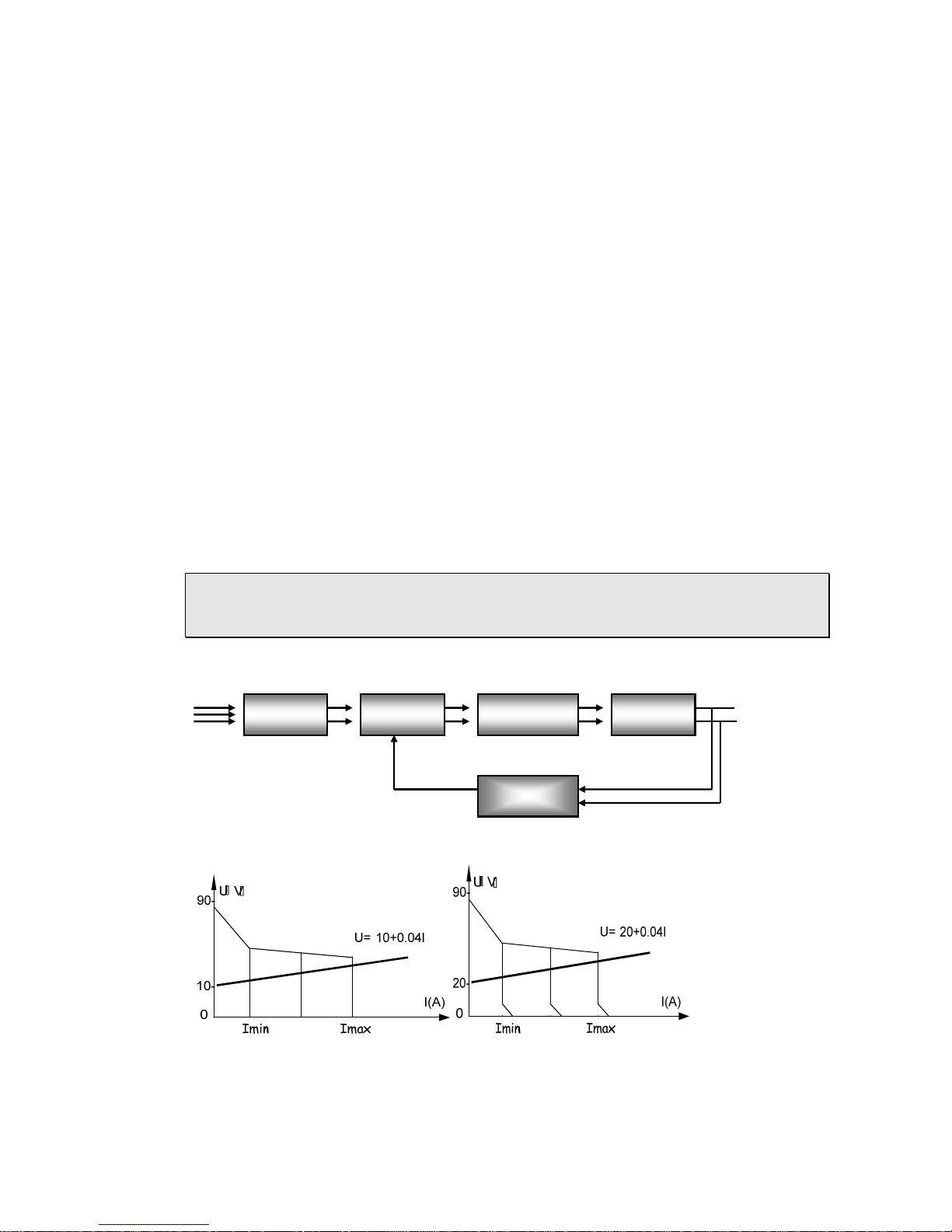
Fig 2 Block diagram of principle
Fig 3a TIG Output Characteristic Fig 3b SMAW output characteristic
3~380V/50Hz
Rectifier HF inverter Main transformer
Rectifier Filter
Control circuit
+
Page 8

-8-
This series welding machines apply IGBT soft switch inverter technology.
3- phase input volt are rectified by rectifier, inverted into HF AC, reduced
by HF transformer, rectified and filtered by HF rectifier, then output DC
power suitable for welding. After this process, the welder’s dynamically
responsive speed has been greatly increased, so the welder size and
weight are reduced noticeably result in energy saving. Power source enjoy
sound anti-fluctuating ability and high-quality performance during
external context changes (As to fluctuation in input power supply and
extended welding cables). Easy to arc start, stable arc length, pretty weld
formation and capability of continuous regulation the current of welding,
arc-starting and arc force as well as time of down-slope add significant
values to customers. They have down-slope, pre-gas flow and post-gas
flow function due to reasonable logic circuit design.
Operating Instruction
1. Function introduction
1.1 Front panel illustration and parts number reference
Fig.4: Front panel
Page 9
-9-
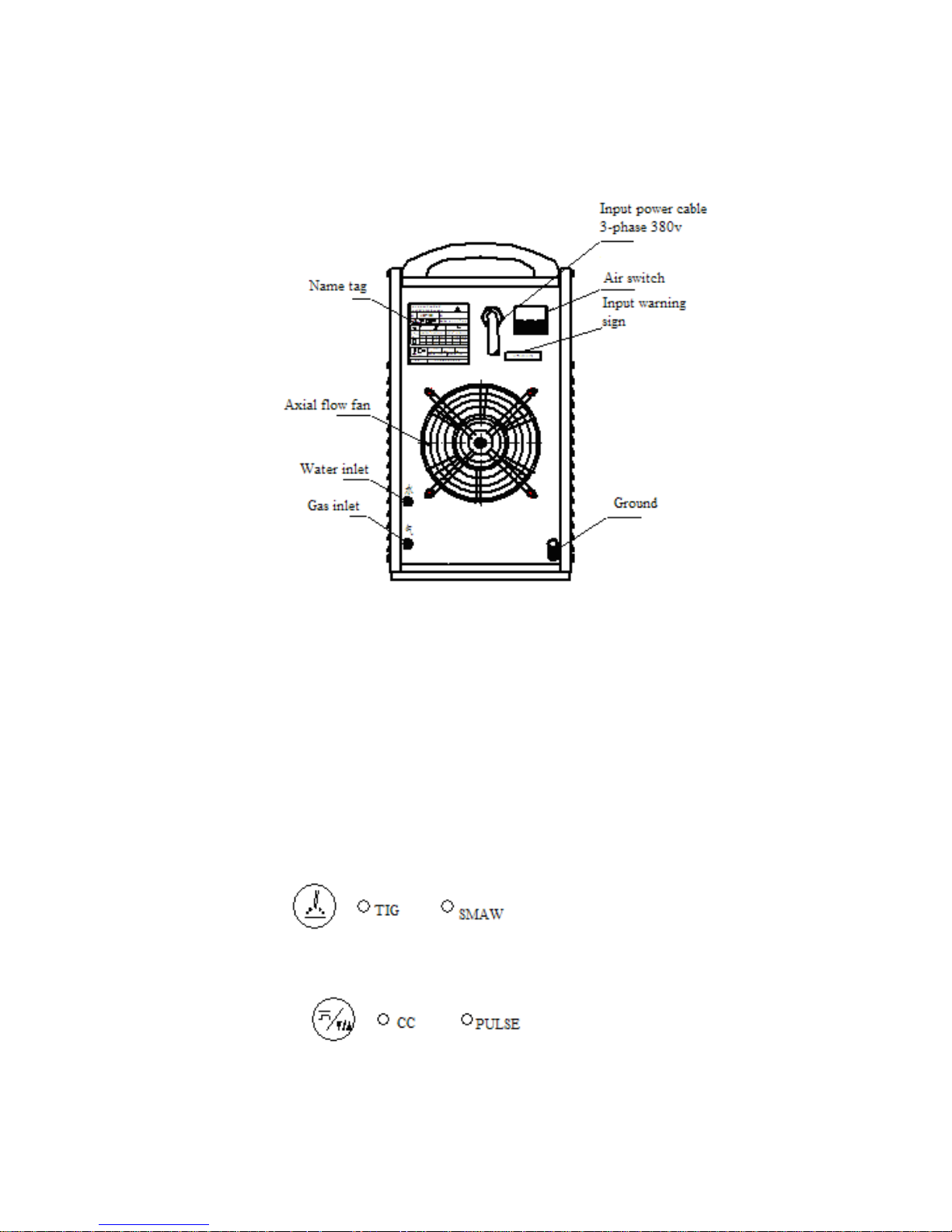
1.2 Rear panel illustration and parts number reference
Fig.5: Rear panel
1.3 Control panel
The machine’s control panel drawing for mode selection and parameters preset
shows as figure (6). Control panel includes LED alphanumeric display, tuning knob,
diode indicator lamps.
Fig.6: Control panel
1.3.1 Mode selection and parameters preset
“TIG /MMA” shift
On “TIG”: Switch between “Constant” DC TIG and “Pulse” DC TIG
On “MMA”: Switch between “Amp” Display and “Volt” display
Page 10
-10-
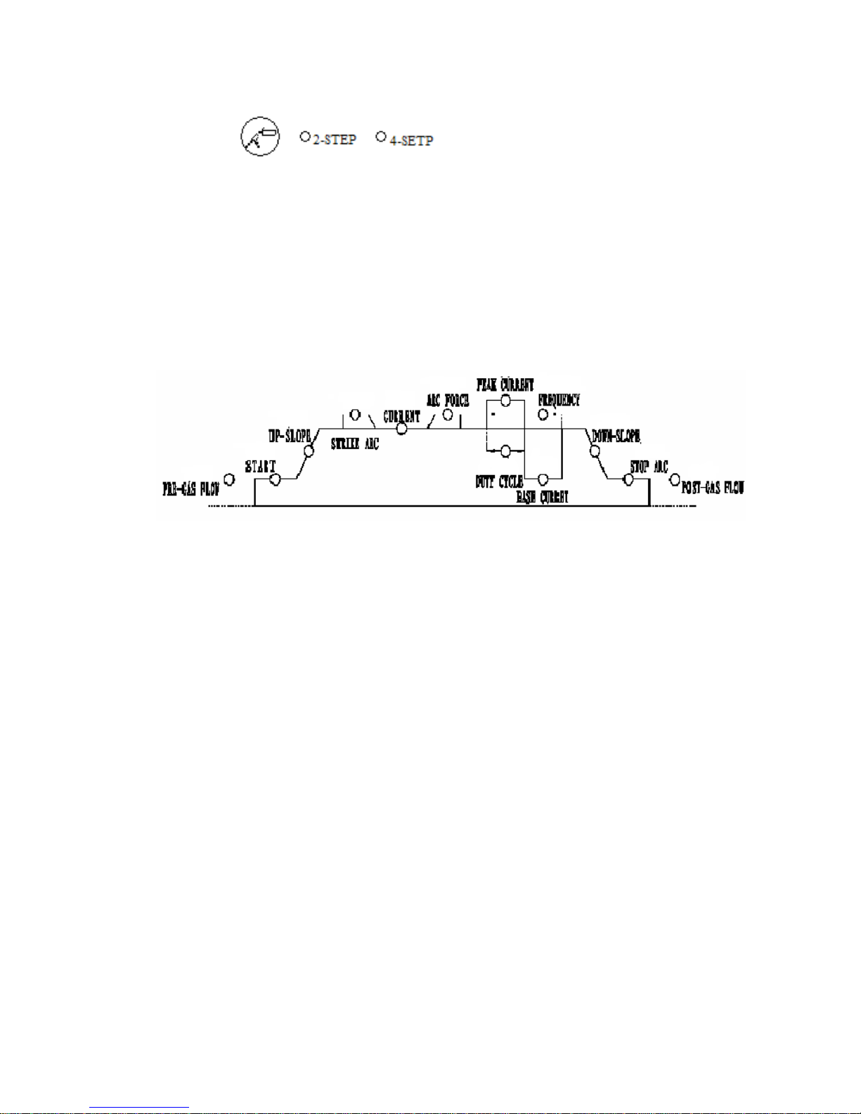
Switch between “2- Step” (Non-Autolock) and “4-Step” (Autolock) on TIG
“2-step” refers to start welding while push torch trigger, stop welding while releasing
it.
“4-step” refers to starting-arc current while firstly pushing torch trigger, then current
slopes up to where can welding normally while releasing it. When welding finished,
current slopes down to where stops arc and stands while pushing it again, then stops
output current while releasing it.
Glossary:
1、Pre-gas flow: time of gas flow before welding
2、Arc-starting: current of start arc
3、Up-slope: time of welding current slopes up
4、Arc-striking: current of start arc on MMA
5、Constant current: welding current in constant output state
6、Arc-force: current of arc- force on MMA
7、Peak value: Peak current of pulse output
Page 11

-11-
8、Pulse ratio: time ratio between length of peak value current and length
of whole single pulse, can be used for controlling penetration in
all-position or thin sheet welding.
9、Pulse frequency: frequency of pulse output.
10、Base current: current of arc-stand in pulse output.
11、Down –slope: time of welding current slopes down
12、Crater filling: current of crater filling
13、Post-gas flow: time of gas flow after ending welding
Parameters selection knob: used to select parameters illustrated previously. Select
consequently from left to right by tuning clockwise, select reversely by tuning
counter-clockwise.
Parameter regulation knob: Used to adjust value of the selected parameters. Increase
by tuning clockwise, reduce by tuning counter-clockwise. Press the knob and tune
clockwise or counter-clockwise for quick preset.
“Water cooled/Air cooled” shift: Default set-up is “Water–cooled”. If “Air-cooled” is
selected, then press on “Parameter Selection” and “Parameter regulation” knobs
simultaneously for two seconds to eliminate “Water insufficient” protection in order
to normal welding. Redo the same procedure to come back to the previous mode.
Welder can automatically save settled parameters for next time using while turning
off the machine.
1.3.2 “Protection” indicator lamp: lights on yellow and stops welding automatically
while in overheat or water insufficient, but will not light on while in normal welding.
1.3.3 Protection code:
Display 804: overheat protection
Display 805: On TIG welding, push welding torch trigger for too long time in
open load or trigger damaged.
Page 12
-12-
Display 806: water insufficient protection
1.3.4 Power on/off lamp: display red when power on
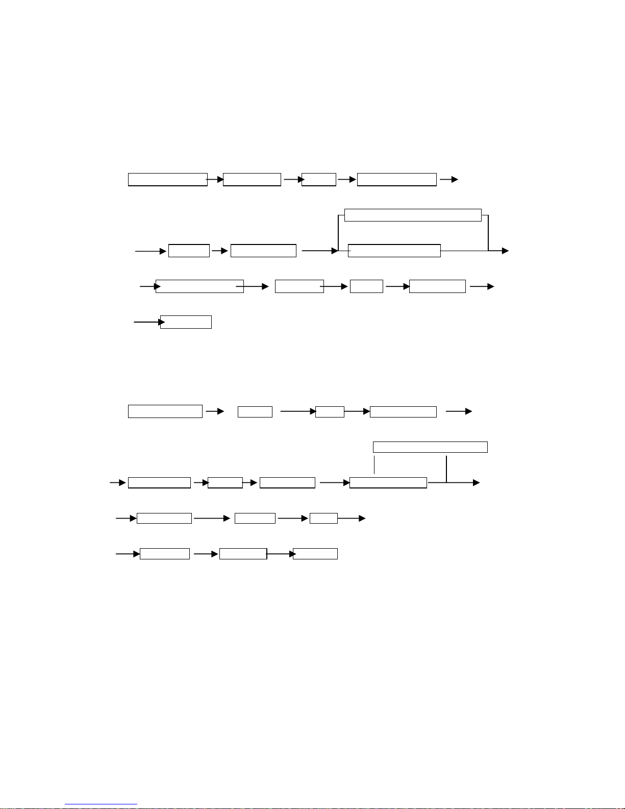
2. Procedures of TIG welding
2.1”2-step”
push torch trigger pre-gas flow arc-start arc-starting current
constant current TIG arc welding
up-slope normal welding pulse TIG arc welding
release torch trigger down-slope stop arc post-gas flow
end welding
2.2”4-step”
push torch trigger pre-gas flow arc-start arc-starting current
constant current TIG arc welding
release the trigger up-slope normal welding pulse TIG arc welding
push the trigger down-slope stop arc
release trigger post-gas flow stop welding
3. Welding parameters
Page 13
-13-
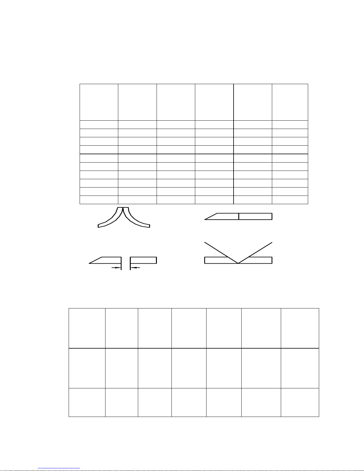
3.1 TIG welding parameters
Sheet
thickness
(mm)
Tungsten
electrode
diameter
(mm)
wire
diameter
(mm)
Welding
current
(A)
Gas flow
rate
(L/min)
Clearance
(mm)
0.4 1.0-1.6 0-1.0 5-30 4-5 1
1.0 1.0-1.6 0-1.6 10-30 5-7 1
1.5 1.0-1.6 0-1.6 50-70 6-9 1
2.5 1.6-2.4 1.6-2.4 70-90 6-9 1
3.0 1.6-2.4 1.6-2.4 90-120 7-10 1-2
4.0 2.4 1.6-2.4 120-150 10-15 2-3
5.0 2.4-3.2 2.4-3.2 120-180 10-15 2-3
6.0 2.4-3.2 2.4-3.2 150-200 10-15 3-4
8.0 3.2-4.0 3.2-4.0 160-220 12-18 4-5
12.0 3.2-4.0 3.2-4.0 180-300 12-18 6-8
①
②
③ ④
3.2 MMA welding parameters
Work
piece
thickness
(mm)
≤1
1~2 2~3 4~5 6~12
≥13
Welding
electrode
diameter
(mm)
1.5 2 3.2
3.2~4 4~5 5~6
Welding
current
(A)
20~40 40~50 90~120 90~130 160~250 250~400
Page 14

-14-
Repair & Maintenance
Warning: Should not open up case freely, the max volt inside machine
will be 600V. Must take safe precautions to prevent from being electric
shocked while in maintenance.
1. Apparently misunderstand failures
Normal phenomenon occurs in welding
(1) Welder doesn’t work while in pretty low input volt.
(2) When welder has worked for a long time in high temperature or
in high welding current context , the thermal-sensitive circuit breaker
will tripped to stop welder working, protection lamp will light on
and LED will show “804” protection code. Welder will automatically
reinstate after merely running up for several minutes in open load
(not necessarily shut down welder).
(3) When welder has worked for a long time in high temperature or
in high welding current context, the circuit breaker on the rear panel
will tripped to power off. When this situation occurs, please switch
off the disconnected switchboard. Then halt the welder lasting at
least five minutes to restart. When restarting the welder, please reset
the circuit breaker firstly, then turn on the disconnect switchboard or
switch box to power on welder, finally use for welding after running
up for several minutes in open load.
2.Attention
1. The input volt range must be between 340-420V, and no phase
missing.
2. Check if the ground leads are connected correctly and firmly.
3. Must wires welding cable to terminal plug socket firmly, otherwise
will burn out the terminal which lead to welding process
instability.
4. Power off as soon as finished welding
5. When use in outdoor, make sure welder be shielded from rains or
snows, but don’t block air circulation.
Page 15

-15-
3. Troubleshooting
3.1 Routine checking procedure prior to maintenance
1. Check if the input volt has the phase to be lost, and range are
between 340-420V.
2. Check if the power input cables are correctly and firmly.
3. Check if the ground leads are connected correctly and firmly.
4. Check if the cables are connected correctly and firmly
3.2 Regular troubleshooting & countermeasure .Refer to appendix A.
4. Periodical check and maintenance
1. Must removes dust from power resource with pressure air by
authorized maintainer each year while checking if the jointers are
loose. Must check frequently if quick plug or terminal sockets are
loosely connected, knobs are loose, at least per month.
2. Must check if knobs are loose connection in time.
Page 16
-16-
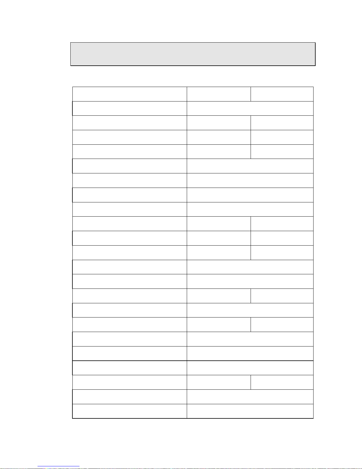
Technical Data
1. Main technical parameters
Item IN TIG-315 P IN TIG-400 P
Rated output volt 3 phase 350 ~ 465 V/50Hz
Rated input volt 13.8KVA 18.4KVA
Rated input current 21A 28A
Duty cycle 35%
60%
Pre-flow gas 0.1-15s
Striking arc current
10-160A
Slope up time 0.1-10s
Arc-starting current 20-160A
Constant current 5-315A 5-400A
Arc Force current 10-100A 10-200A
Peak current 5-315A 5-400A
Pulse percentage 1%-100%
Pulse frequency 0.2-50Hz
Base current 5-315A 5-400A
Slope down time 0.1-15s
Stop-arc current 5-315A 5-400A
Post flow time 0.1-15s
Efficiency
89%
Power factor 0.95
Weight 30kg 35kg
Main transformer insulation grade H
Output reactor insulation grade B
Page 17

Page 18

-18-
Appendix A: Ordinary failures, probable cause & countermeasures
№ Trouble Probable cause Remedies
1
Indicator lamp does not
light on and doesn’t work
when machine switches on.
① Phase missing
② Fuse size(2A)
breaks
③ Input cable break
down
① inspect power
source
② Inspect fan, power
source transformer and
control board are in
good condition or not
③ Inspect cable
2
Air switch trips
automatically while welder
working on without big
welding current for long
time
① The following
components may
probably damaged:
IGBT module, 3 phase
rectified module,
output diode module,
other components
② Short circuited
Inspection and
replacement
3
Welding current is not
stable.
① Phase missing
② Main control board
is damaged.
① Inspect power
source
② Inspection and
replacement
4
Welding current is not
adjustable.
① Conductive wires
broken.
② Main control board
is damaged.
③ Coder damaged
Inspection and
replacement
5
Protection code displays
804
① Welding current is
too big
② Context temperature
is too high.
③ Thermal relay is
damaged
① Needs zero load
cooling
② Replace
temperature relay
6
displays 805 protection
code
① torch is damaged
② torch trigger has
been pushed for a long
time in open load
Inspect the torch and
replace it
release the trigger
Page 19
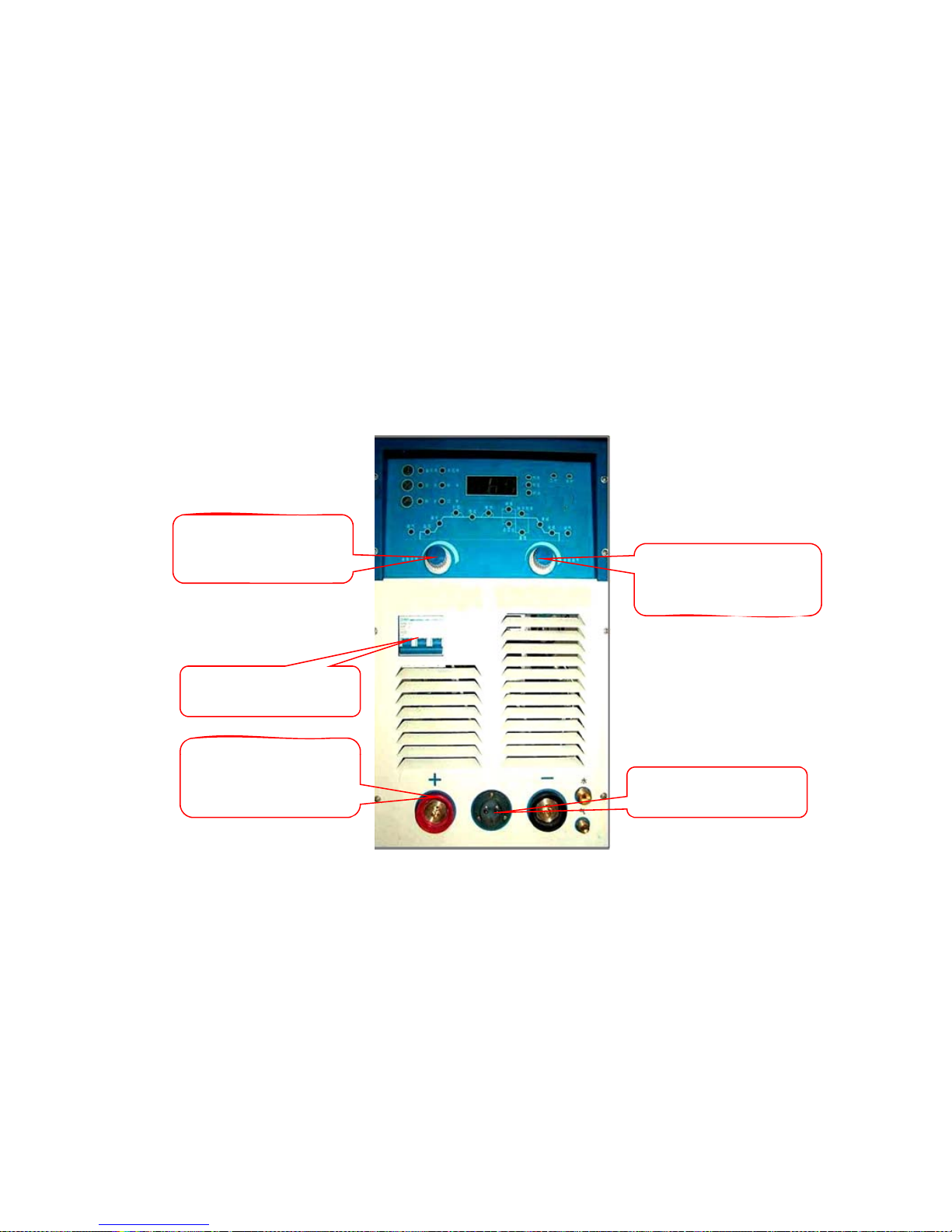
Front Panel
Encoder for
Encoder for
Parameter
Parameter Setting
(ENC01)
Selecti
on
(ENC01)
MCB (MCB001)
Output Connector
EURO Type (OCN-
EURO-S)
2 Pin Connector
Male (CON2PNM)
Page 20
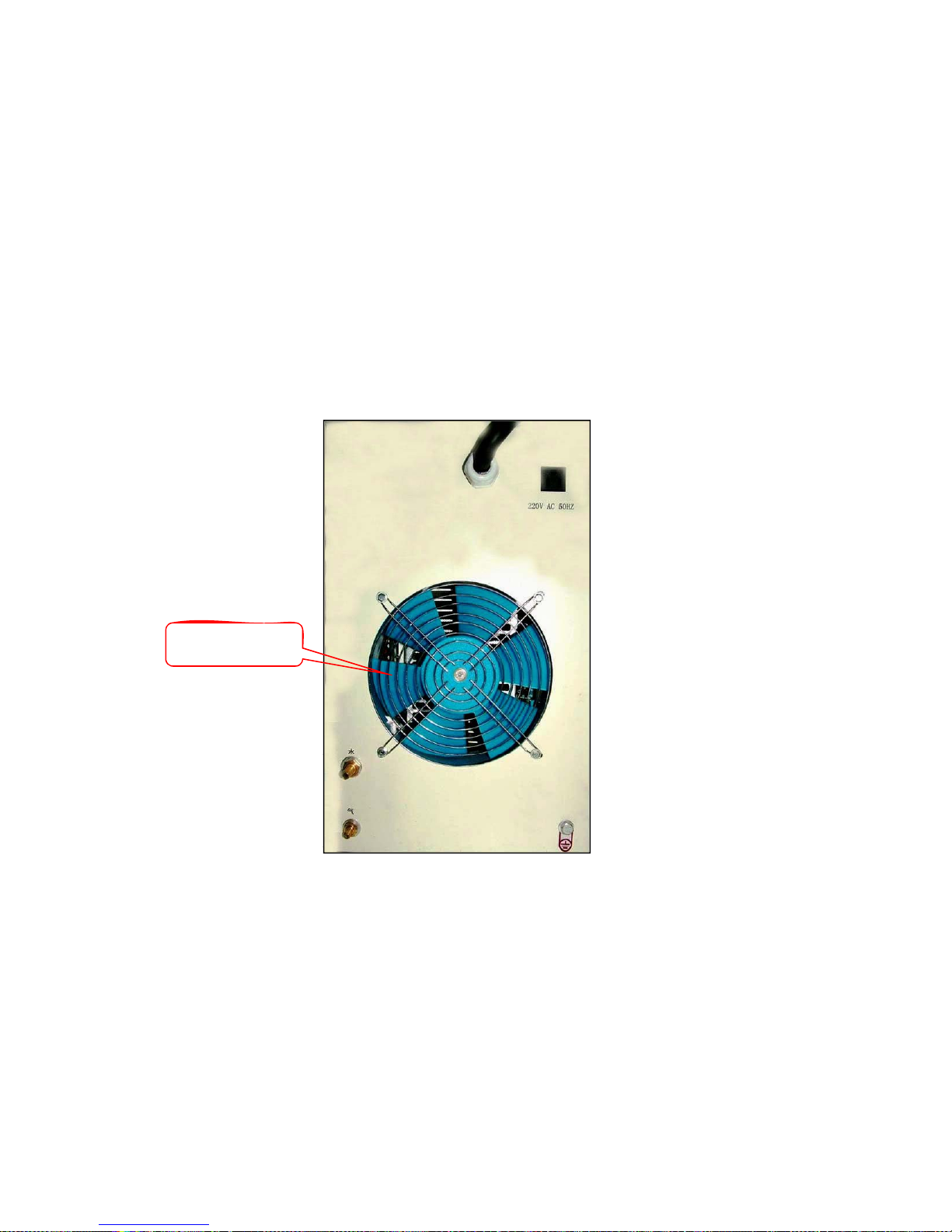
Rear Panel
Fan (FAN002)
Page 21
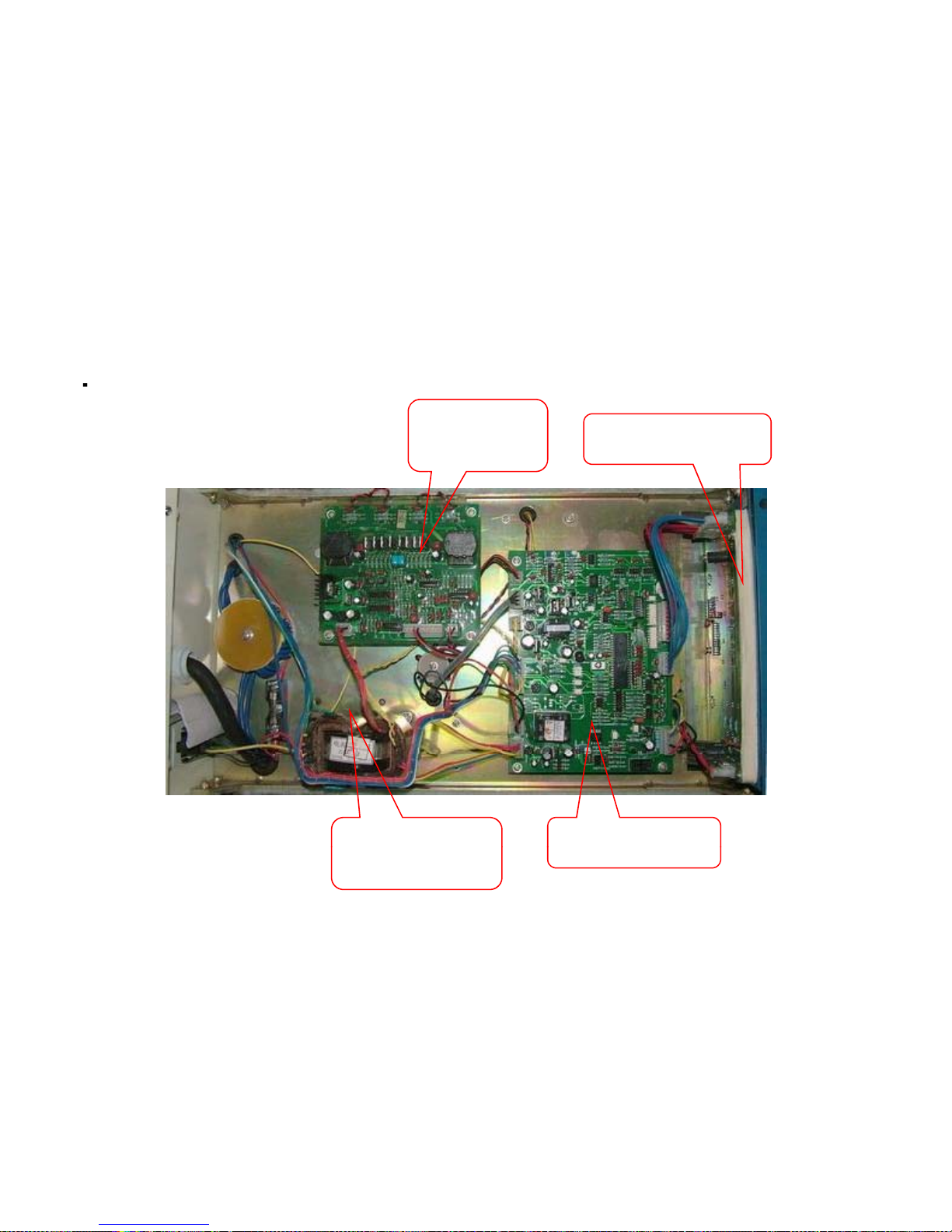
Top View
p
Drive Card
(PCB-DRV-
01U)
Display PCB (PCB-
DSP-TIGPLS-01)
Control
Main PCB (PCBTransformer
(CTRAX004)
TIGPLS-315I)
Page 22

Right View
g
SNUBBER CARD
(PCB-SNB-04)
O
ver Current Protection
PCB (PCB33)
AC
IGBT
(IGBT50R12)
Capacitor
(CAP002)
Input Bridge
Module
(IBDG003)
HF PCB
(PCB-HF-01)
Water Flow
Switch
(WFS-50W)
MOV
(MOV001)
DC Capacitor
(CAP001)
F
an Capacitor
(CAP005)
Solonaid Valve
(SV001)
HF T
ransformer
(CTRA007)
Page 23
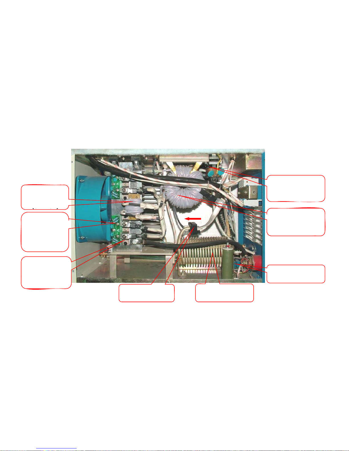
Left View
Secondary
Thrust Coil
-
Insulation
Transformer
(INSTRX001)
Main
Transformer
(MTRAX006-P)
(S
THCL)
Snubber
PCB for
Output FRM
Isolation PCB
Output
Rectifier
(PCB
-
SNB
-
OUT-01)
(PCB-ISO-02)
Output Choke
(CHK001)
Modul
e
(FRM001)
Current Sensor
(CS001)
Page 24
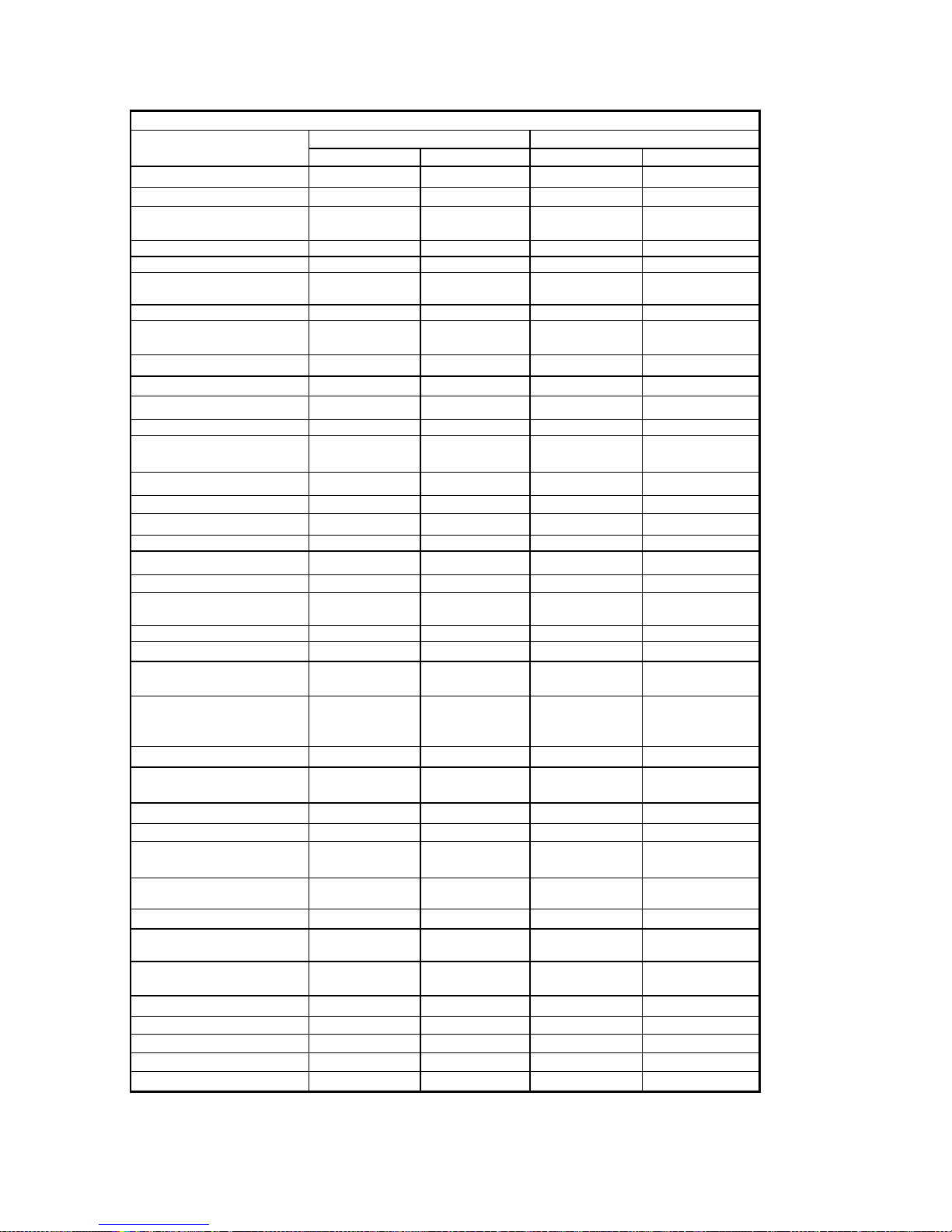
-
-
List for the spares of INTIG-PULSE Series Machines
DESCRIPTION
MAIN PCB PCB-TIGPLS-315I PCB-TIGPLS-400I
DRIVE CARD PCB-DRV-01U PCB-DRV-01U
DISPLAY PCB
IGBT IGBT50R12 NA IGBT50R12 NA
SNUBBER CARD PCB-SNB-04 PCB-SNB-04
IGBT WITH SNUBBER CARD IGBT50R12SNB
INPUT BRIDGE MODULE IBDG003 100 Amps 1200V IBDG003 100 Amps 1200V
OUTPUT RECTIFIER
MODULE
FAN FAN002 FAN002
DC CAPACITOR CAP001 20UF 1400V CAP001 20UF 1400V
AC CAPACITOR CAP002 4 UF 500 V CAP003 5UF 500V
MCB MCB001 40 Amps MCB002 40 Amps
INPUT SURGE
SUPPRESSOR
SNUBBER CAPACITOR SCAP001 0.47UF 1200V SCAP001 0.47UF 1200V
CONTROL TRANSFORMER CTRAX004 CTRAX004
OUTPUT CHOKE CHK001 CHK001
HF PCB PCB-HF-01 PCB-HF-01
HF PCB CAPACITOR PCB22.01 PCB22.01
SOLONAID VALVE SV001 SV001
INSULATION
TRANSFORMER
MOV MOV001 MOV001
ISOLATION PCB PCB-ISO-02 PCB-ISO-02
SNUBBER PCB FOR
OUTPUT FRM
ENCODER FOR
PARAMETER SELECTION
AND SETTING
KNOB FOR THE POT (ENC) KNOB001 KNOB001
OVERCURRENT
PROTECTION PCB
MAIN TRANSFORMER MTRX006-P MTRX002
FAN CAPACITOR CAP05 CAP05
OUT PUT CONNECTOR
MACHINE SIDE
OUT PUT CONNECTOR
CABLE SIDE
2 PIN CONNECTOR MALE CON2PNM CON2PNM
2 PIN CONNECTOR FEMALE
CABLE SIDE
OUTPUT CONNECTOR
EURO TYPE WITH STRIP
CURRENT SENSOR CS001 CS001
SECONDARY THRUST COIL S-THCL-315 S-THCL-400
LED RED LEDR01 LEDR01
WATER FLOW SWITCH WFS-50W WFS-50W
LED YELLOW LEDR01 LEDY01
PCB-DSP-TIGPLS
01
PCB-SNB-OUT-01 PCB-SNB-OUT-01
CON-2-CM-F-01 CON-2-CM-F-01
INTIG-315 PULSE INTIG-400 PULSE
Part/Code SPEC. Part/Code SPEC.
PCB-DSP-TIGPLS
01
50R12SNB ( 50
Amps 1200V)
FRM001 200 Amps 400V FRM001 200 Amps 400V
ISS001 ISS001
INSTRX001 INSTRX001
ENC01 ENC01
PCB33 PCB16
FST-PLG-F-01 FST-PLG-F-01
FST-PLG-M-01 FST-PLG-M-01
OCN-EURO-S OCN-EURO-S
IGBT50R12SNB
50R12SNB ( 50
Amps 1200V)
 Loading...