

Page 1

INTIG 316/501 AC/DC
Inverter AC/DC Pulsed Argon Arc Welding Machine
OPERATOR’S MANUAL
(PLEASE READ CAREFELLY BEFORE OPERATION)
Page 2

INTIG 316/501 AC/DC
-1-
Safety Depends on You
our arc welding and cutting equipment's are designed and built with ample safety consideration. However, proper installing and
operating the machine can increase your safety.
DO NOT INSTALL, OPERATE OR REPAIR THIS EQUIPMENT CASUALLY WITHOUT READING THIS
MANUAL THROUGHOUT.
Special
Attention (Very Important):
● PLACE THE MACHINE ON A PROPER PLANE, SO THAT THE MACHINE DOES NOT
SLIP.
● PLEASE KEEP THE MACHINE AWAY FRO M RAIN ( UNDER PROPER ROOFING ).
● READ THE INSTRUCTION MANUAL CAREFU LLY BEFORE OPERATE THE MACHINE.
Purchase Date:
Serial Number:
Machine Type:
Purchase Place:
Page 3
INTIG 316/501 AC/DC
-2-
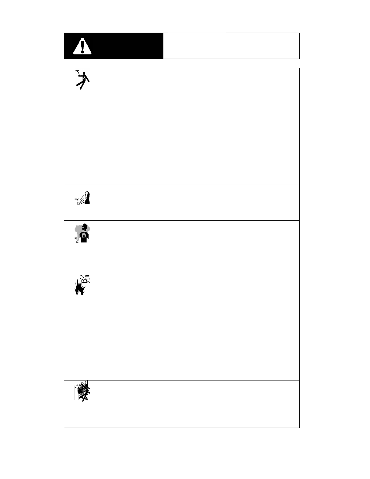
Cautions
Arc and arc rays can hurt.
1
Electric shock: The welding circuits are not insulated when welding. If you touch the
two
output
electrodes
of
the
machine
with
your
bare
skinatthe
same
time,itwill
lead
to
electric
shock,
sometimes
even
fatal
dangers.
Users
needtofollow
the
items
below
to
avoid electric shocks:
If
possible,
lay
some
insulating
materials,
which
are
dry
and
large
enough,
in
your
working
field.
Otherwise, use the automatic or semiautomatic welding machine, DC welding machine as possible as you
can.
Components in the automatic and semiautomatic welding machine such as the welding wire reel, feed
wheel, contact tip and welding head are all electriferous.
Always
be
sure
the
machine
has
been
connected
perfectly
to
the
work
piece
with
the
work
cables
and
should be as close as possible to the working area.
The work piece should be grounded perfectly.
Make
sure
that
the
insulating
material
of
the
electrode
holder,
the
grounding
clamp,
the
welding
cable
and
the welding head are not affected by damp, mildewed or spoilt, and be replaced momentarily.
Never
dip
the
electrode
in
water
for
cooling.
Never touch electriferous parts of two welding machines at the same time, because this voltage is
supposed to be two times of welding voltage while the grounding mode is not clear.
While
working
high
above
the
ground
or
other
places
having
the
riskoffalling,
please
be
suretowear
safety
belttoavoid
losing
balance
caused
by
electric
shock.
2
Arc: Use an arc welding mask to protect your eyes and skin from sparks and the rays of
the
arc,
pay
special
attention
to
the
filter
glass,
which
mustbeconformable
to
the
national
standard.
Use
clothing
made
from
durable
flame-resistant
material
or
sailcloth
to
protect
your
skin
from hurting by the arc rays.
Remind
other
nearby
personnel
before
working
lest
arc
rays
hurt
thembyaccident.
3
Fumes and Gases: Welding may produce fumes and gases hazardous to health. Avoid
breathing
these
fumes
and
gases.
While
working
in
limited
room,
use
enough
ventilation
and/or
exhaust
to
keep
fumes
and
gases
away
from
the
breathing
zone,oruse
the
respirator.
Do
not
weldatthe
same
time
when
usingofdegreasing,
cleaning
or
spraying
operations. The heat and rays of the arc can react with these gases to form phosgene, a highly toxic gas,.
Some
protective
gases
usedinwelding
might
displace
the
oxygen
in
the
air,
and
can
leadtohurtoreven
death.
Read and understand the manufacturer’s instructions for this equipment, and validate the health
certification of consumptive materials, make sure they are asepsis and innocuity.
4 Spatter: Spatter can cause fire or explosion.
Remove fire hazards from the welding area. Remember that spatter from welding can
easilygothrough
small
cracks
and
touch
fire
hazards.
Keep
the
safety
of
all
kinds
of
lines
going
though
welding
area,
including
hydraulic
linesinthe
wild.
Where
compressed
gases
aretobe
usedinthe
field,
special
precautions
should
be
usedtoprevent
explosion.
When not welding, make certain that no electriferous part is touching the work piece or the work stage.
Accidental contact can create a fire hazard.
Do
not
weld
containers
or
lines,
which
are
not
proved
tobeinnocuity.
It is very dangerous to heat, cut or weld tanks or containers at entry holes. Does not start work until the
proper steps have been taken to insure that there are no flammable or toxic gases there.
Spatter
might
cause
burn.
Wear
leather
gloves,
heavy
shirt,
cuffless
trousers,
high
shoes
andacap
over
your hair to prevent from burning by spatter. Wear the ear shield when performing sideways or face up
welding. Always wear safety glasses with side shields when being in a welding area.
The welding cables should be as close to the welding area as possible, and the short, the better. Avoid
welding cables going through the building framework, lifting chains, AC or DC cables of other welding
machines and appliances. The welding current is strong enough to damage them while having short circuit
with
them.
5
Cylinder: Damage of it might cause explosion.
Make
sure
that
the
gasinthe
storage
cylinder
is
qualified
for
welding,
and
the
decompression
flowmeter,
the
adapter
and
the
pipe
are
allingood
condition.
Make
sure
that
the
installation
of
cylinder
isbythe
wall
and
bundled
tightly
byachain.
Be sure to put the cylinder in the working space with no crash or shake, and far from welding area.
Itisforbidden
to
touch
cylinder
with
the
welding
clamp
or
the
work
cables.
Avoid
facing
the
cylinder
while
installing
the
decompression
flowmeter
or
the
gasometer.
When
not
working,
please
tighten
the
valve.
Page 4
INTIG 316/501 AC/DC
-3-
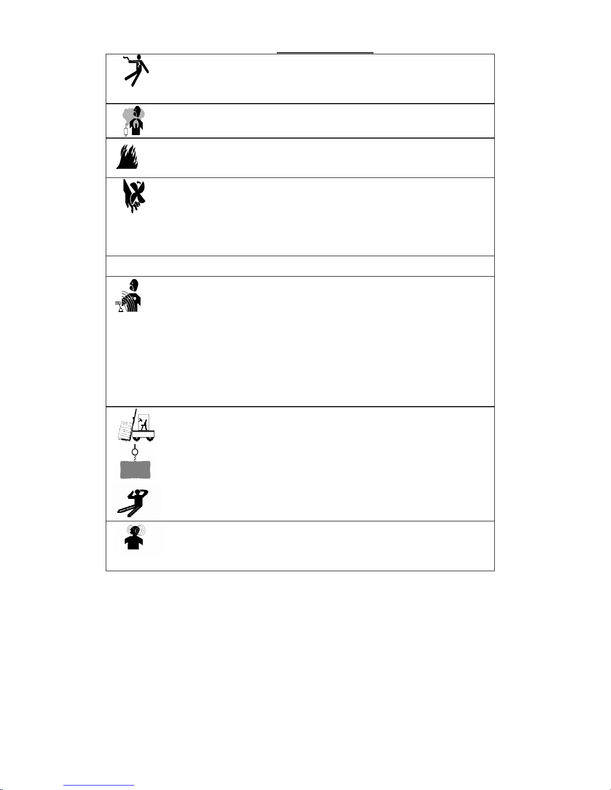
6
Power: (For electrically powered welding and cutting equipment) Turn off input power
before
installation,
maintenances
and
repair,
so
that
avoid
accident.
Huanyuan
welding
equipment
isΙclass
safeguard
equipment;
please
install
the
equipment
by
manufacture
’sprofessional
person
Ground
the
equipment
perfectly
in
accordance
with
the
manufacturer
’srecommendations.
7 Power:(For engine driven welding and cutting equipment)
Workinventilated
placeoroutdoors.
Do not add fuel near to fire or during engine starting or welding. When not working, add
fuel
after
engine
is
cooling
down;
otherwise,
the
evaporation
of
hot
fuel
would
result
in
dangers.
Do
not
splash
fuel
outofthe
fuel
tank,
anddonot
start
the
engine
until
complete
evaporation
of
the
outside
fuel.
Make sure that all the safeguard equipment's, machine cover and devices are all in a good
condition.
Be
sure
that
arms,
clothes
and
all
the
toolsdonot
touch
all
the
moving
and
rotating
components
including
V
belt,
gear
and
fan
etc.
Sometimes
having
to
dismantle
some
partsofthe
device
during
maintenance,
but
must
keep safety awareness strongly every time.
Do
not
put
your
hand
closetofans
anddonot
move
the
brake
handle
while
operating.
Please
remove
the
connection
between
the
engine
and
the
welding
equipment
to
avoid
sudden
starting
during
maintenances.
When
engine
is
hot,itis
forbidden
to
open
the
airtight
coverofthe
radiator
water
tanktoavoid
hurtbythe
hot vapor.
8 Electromagnetic: Welding current going though any area can generate electromagnetic,
as
wellasthe
welding
equipment
itself.
Electromagnetic
would
affect
cardiac
pacemaker,
the
cardiac
pacemaker
users
should
consult
one’s
doctor
first.
The
effectofelectromagnetic
to
one’s
health
is
not
confirmed,
soitmight
have
some
negative
effect
to
one’s health.
Welders
may
use
following
method
to
reduce
the
hazardous
of
electromagnetic:
a. Bundle the cable connected to the work piece and the welding cable together.
b. Do not enwind partially or entirely your body with the cable.
c. Do not place yourself between the welding cable and the ground (work piece) cable, if the welding cable
is by your left side, then the ground cable should be by your left side too.
d. The Welding cable and the ground cable are as short as possible.
e. Do not work near to the welding power source.
9
Lift equipment: carton or wooden boxes package the welding machines supplied by
Warpp
Engg.Thereisno
lifting
equipment
in
its
wrapper.
Users
can
moveitto
the
prospective
areabya
fork-lift
truck,
then
open
the
box.
If
their
are
rings,
the
machine
canbetransited
using
rings.
While
our
Welding
Machine
Manufacture
reminds
users,
thereispossible
risktodamage
the
welding
machine.
It
is
bettertopush
the
welding
machine
moving
in
useofits
rollers
unless
special
situations.
Be
sure
that
the
appurtenances
are
all
removed
off
when
lifting.
When
lifting,
make
sure
that
thereisno
person
below
the
welding
machine,
and
remind
people
passing
byatany
moment.
Do
not
move
the
hoist
too
fast.
10
Noise: our Welding Machine Manufacture reminds users: Noise beyond the limit (over
80
db)
can
cause
injury
to
vision,
heart
and
audition
depending
on
oneself.
Please
consult
local
medical
institution.
Use
the
equipment
with
doctor
’spermission
would
helptokeeping
healthy.
Page 5

INTIG 316/501 AC/DC
-4-
1. Features and Usage -------------------------------------------------5
2.
Working
Conditions
and
Environment:
------------------------5
3. Technical specification---------------------------------------------6
4. Product System Introduction-------------------------------------6
5. Product Construction Introduction -----------------------------7
6. Installation ----------------------------------------------------------13
7. Operation Introduction ------------------------------------------14
8. Trouble shooting ---------------------------------------------------18
9. Packing list and appendix ----------------------------------------21
10. INTIG 316 AC/DC electric schematic -------------------------22
11. INTIG 501 AC/DC electric schematic --------------------------23
12. Welding machine Picture’s ---------------------------------------24
13. Spare parts List for INTIG 316, 501 AC/DC -----------------26
Page 6

INTIG 316/501 AC/DC
-5-
1.
Features
and
Usage:
INTIG AC/DC series pulsed TIG welding machine has the function of DC TIG welding, DC pulsed TIG
welding, AC TIG welding, and AC pulsed TIG welding. It is a kind of tungsten TIG welding machine
incorporated multi-function.
The primary inverter of INTIG AC/DC series pulsed TIG welding machine adopts the latest IGBT and fast
recovery diode etc , the invert frequency is 20KHZ. The small mid-frequency transformer replaced the heavy
industrial frequency transformer, which has the advantages of high efficiency, low no-load loss, stable current,
energy saving, material saving and high reliability etc..
The secondary inverter of INTIG AC/DC series pulsed TIG welding machine adopts the half-bridge inverter
circuit, which has advantages like adjustable frequency and pulse width , good reliability and energy saving etc
INTIG AC/DC series pulsed TIG arc welding machine has all functions required for welding technique. The
functions like high frequency arc striking, gas pre-flow (adjustable), initial current (adjustable), current
upslope (adjustable), current down slope (adjustable), crater current (adjustable), gas post-flow etc are
available in the machine. During the AC TIG welding the cleaning action of welding is adjusted by AC WAVE
BALANCE and also AC frequency is adjustable which is useful to control the bead of the welding. The
machine can be used for ordinary welding as well as pulsed welding. The advantage of the pulsed welding is
variation in the high and low welding current, better arc stiffness due to the electromagnetic pinch effect, the
melting time for the metal is short, so the weld seam is much more fine with higher strength. The form of weld
seam surface could also be changed through changing the four pulse parameters, so it could also decided by
welding machine.
This welding machine can mainly used for all metals like aluminum, magnesium, copper, stainless steel
on pipe, boiler, aviation, etc.
2.
Working
Conditions
and
Environment:
1. Input power
1.1 The exact input voltage wave shape should be sine wave, the frequency fluctuation should be no more than
+1% of the rated value.
1.2 The fluctuation of input voltage must be within 380 to 440 VAC.
1.3 Imbalance between phase should not exceed 5%.
2. Environment:
A. Ambient temperature ranges:
Welding temperature range: -10⁰C ~ +40⁰C
Transportation and Storage temperature range: -25⁰C ~ +55⁰C
B. Operating area must be dust free for better usage of the machine.
C. Operating altitudes: less than 1000m
D. Wind speed should be no more than 1m/s
E. Avoid exposing the machine to direct sunlight and rain.
3. Technical Specification:
Model
Parameter
INTIG 316 AC/DC INTIG 501 AC/DC
Input power
380 - 440 vac 50/60 Hz
Rated input capacity(KVA) 11.9 21
Page 7

INTIG 316/501 AC/DC
-6-
Rated input current(A) 18.2 31.8
Open circuit voltage(V) 82 85
Rated welding current(A) 315 500
Rated welding voltage(V) 22.6 30
Rated duty cycle(%) 60% 60%
Gas pre-flow time(S) 0.0 ~ 5.0
Initial current adj.
range(A)
AC 20 ~ 315 20 ~ 500
DC 10 ~ 315 10 ~ 500
Current upslope time(S
)
0.0 ~ 10.0
Welding current
adj. range(A)
AC 20 ~ 315 20 ~ 500
DC 10 ~ 315 10 ~ 500
Peak current adj.
range(A)
AC 20 ~ 315 20 ~ 500
DC 10 ~ 315 10 ~ 500
Pulse frequency(Hz) 0.2 ~ 99.9
PWM ratio(%) 10% ~ 90%
Base current adj.
range(A)
AC 20 ~ 315 20 ~ 500
DC 10 ~ 315 10 ~ 500
AC frequency(HZ) 20 ~ 200
Clean width(%) 10% ~ 50%
Current down-slope time(S) 0.1 ~ 15
Crater current adj.
range(A)
AC 20 ~ 315 20 ~ 500
DC 10 ~ 315 10 ~ 500
Gas post-flow time(S) 0.0 ~ 20.0
Dimension(L×W×H)(mm)
705×350×650 725×385×785
Weight(kg) 52 70
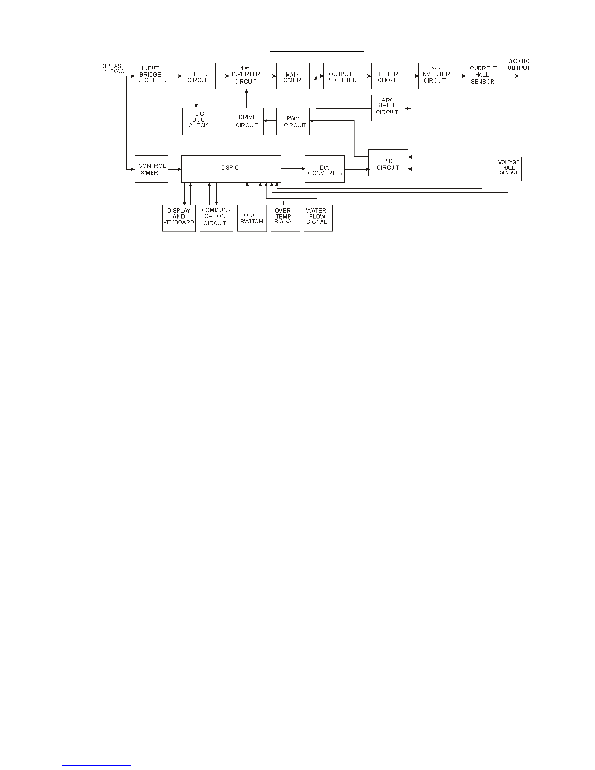
4. Product System Introduction
a) Working principle
INTIG AC/DC series pulsed TIG welding machine adopts AC-DC-AC-DC-AC double inverter circuit. The
primary inverter takes IGBT as the inverter main component. After the three-phase AC input power is rectified
through three phase Bridge rectifier, it is supplied to IGBT inverter, and inverted at 20KHz AC. This is given
as input to main transformer, which steps down the voltage.Output of main transformer given to fast recovery
diode and filter for rectification. Rectified DC is given to secondary inverter section to drive AC output. Which
is used for AC TIG welding operation.
The control circuit controls the output current through pulse width modular. The negative feedback signal
coming from Hallsensor is amplified, then it is fed to negative input end of error amplifier from special PWM
circuit, then it controls the conduction time of IGBT, so that the output current can be kept at required level.
The secondary inverter uses IGBT as the main inverter component, changes the DC current to AC square
wave current, then the square wave required by AC TIG welding is obtained.
This machine has functions of gas preflow, gas postflow , HF arc striking, current upslope, current down
slope. All these functions are controlled by the digital signal programming.
b) Working circuit diagram:
Page 8
INTIG 316/501 AC/DC
-7-
Page 9
INTIG 316/501 AC/DC
-8-
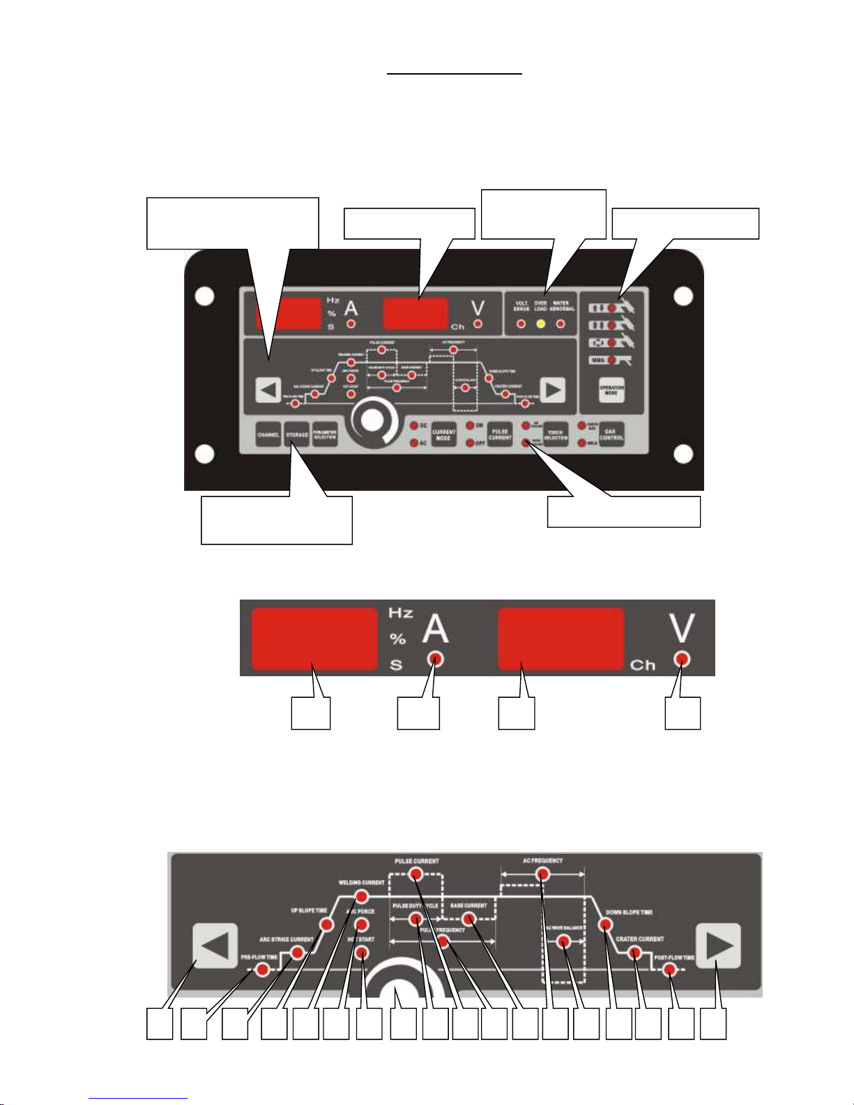
5. Product Construction Introduction
1).Front panel description and function:
The front panel is divided into six areas according to the function:
Diagram 2: Front Panel
2).Digital display area:
A.1stdigital display meter: it is used to display welding/preset current, pulse/AC frequency, pulse width
ratio/clean width, pre-gas time etc.
B.Indicates unit of the parameter being selected.
C. Indicates what second display is showing.
3).Selection and adjusting area of parameters::::
Digital display area
Selection and adjusting
area of parameters
Function selection areaStorage and allocation
area
Protection
indicator area
Operation mode area
A DCB
B C D E F G H I J K L M N OA P Q R
Page 10

INTIG 316/501 AC/DC
-9-
At the time, there is only one indicator is on in this area, which indicates current displayed& adjusted
parameter, and the parameter value is displayed on 1stdigital display meter, adjusted by encoder. When
there is no pulse during working, the welding current is displayed. When there is pulse during working,
the peak current is displayed. The current displayed or adjusted parameter can be selected through
pressing the left or right selection key.
A. Left selection key: press the key, the lighted parameter indicator will move to left, it moves one
after press key one time.
B. Preflow time: adjusting the prflow time.
C. Arc striking current: it is the current when the arc is started.
D. Upslope time: current is transited from arc striking current to welding current(when there is no
pulse)/peak current and base current (when there is pulse)time.
E. Welding current: it is the current when there is no pulse working.
F. Arc force: under the MMA status
G. Hot start:under the MMA status
H. Peak current: it is pulsed peak current when there is pulse working.
I. Rotary encoder: it is used to adjust current displayed parameter.
J. PWM ratio: when there is pulse working, the ratio between peak current time and pulse cycle.
K. Pulse frequency: when there is pulse selected, it is pulsed working frequency (the inverse of
pulse cycle).
L. Base current: when there is pulse selected, it is the base current of pulse.
M. AC frequency: during AC welding, adjusting the current frequency.
N. Clean width: when it is AC welding, adjusting the width ratio of current negative half-wave,
and clean width of negative pole.
O. Down-slope time: the time of current transited from welding current(no pulse)/peak current and
base current(with pulse) to crater arc current.
P. Crater arc current: the current during the arc ending.
Q. Gasflowt time: it is gas-postflow time.
R. Right selection key: press the key, the lighted parameter indicator will move to right, it moves
one after press key one time.
4).Function selection area:
A. Current mode selection key and indicator: select the output current mode(DC/AC).
B. Pulse current key and yes or no indicator: select the current with pulse or without pulse.
C. Welding torch selection key and indicator: when the gas cooling torch is chosen, this switch
should be in gas cooling operation. When the water cooling torch is chosen, this witch should
be in water cooling operation, and water pressure checking function is started.
D. Gas control selection key and indicator: before welding it is in the position of gas checking.
Adjusting the argon flow, after adjusting, when the switch WELD position, the welding
machineswitch ON gas valve and cut off it automatically.
A B
C
D
Page 11

INTIG 316/501 AC/DC
-10-
5).Operation mode area::::
A. Non self-lock: when this indicator is on, the welding machine is the non self-lock status of TIG
welding.
B. Self-lock: when this indicator is on, the welding machine is the self-lock status of TIG welding.
C. Repetition: when this indicator is on, the welding machine is the repeated non self-lock status
of TIG welding.
D. MMA: when this indicator on, the machine is under MMA status
E. Operation mode selection key: this key is used to switch the operation modes of welding
machine.
6).Storage and allocation area::::
A. Pass key: when it is the 1sttime to press this Pass key, voltmeter displays current pass no., and
ammeter displays current storage welding parameters. The left selection key or right selection
key can be pressed to display other parameters stored inside the pass. The storage key can be
pressed to store the current welding parameter into current pass. The allocation key can be
pressed to allocate the storage parameter inside pass as current welding parameter. The pass key
can be pressed to choose next pass. If no key is pressed, it will back out from the pass.
B. Storage key: have current welding parameter stored inside current pass.
C. Allocation key: have current parameter which is stored inside the pass allocated out to use as
current welding parameter.
8). Protection indicator area:
A
B
C
D
A B C
A B
C
E
Page 12

INTIG 316/501 AC/DC
-11-
A. Grid voltage abnormity indicator: when the input voltage is not within 380-440 vac or lacks
phase, this indicator is on.
B. Overload indicator: when the ambient temperature is too high, or the machine is used over the
rated duty cycle, which causes the overheat inside machine, this indicator is on.
C. Water cooling abnormity indicator: when the water cooling torch is used, it shows the water
pressure status. When the water pressure is enough, the indicator is off, when the water pressure
is not enough, the indicator is on.
9). Back panel picture and introduction:
A. Power protection switch: it only used for protection of the over load current.
B. Power input cable: the three phase input cable is fixed on the machine through the screw
connector.
C. Communication interface A: it connects the pedal controller (INTIG 316 AC/DC) or the same
frequency communication interface of double machine (INTIG 501 AC/DC).
D. Communication interface B: it connects wireless controller.
E. Silk print place of name plate.
F. Label place for welding machine series no..
G. Installation place of wireless controller.
H. Cooling fan.
I. Water-returning connector.
J. Water inlet connector.
K. Gas inlet connector: it connects argon relieve valve.
10).Front below panel introduction:
A
B
F
G
K
I
H
J
C D E
A B
C
D
E F
Page 13

INTIG 316/501 AC/DC
-12-
A. Connect workpiece.
B. Connect the plug of welding torch switch.
C. Argon output mouth.
D. Connect welding torch.
E. Connect water-returning mouth of water cooling torch.
F. Connect water-output mouth of water cooling torch.
Preparation before welding
1.Input power capacity and connecting cable:
The input power of this machine is 3 phases, 415V, 50/60HZ. Customer should have the related electricity
cabinet and install the automatic breaker and earth cable. Please connect the green and yellow earth cable on
the machine back with the protection earth cable on electricity cabinet, the outer cable should not be less than
the following table value.
Value
Model
Section surface of input
cable(mm
2)
Breaker
capacity(A)
Section surface of earth
cable(mm
2)
INTIG 316 AC/DC
≥6 40 ≥6
INTIG 501 AC/DC
≥6 60 ≥6
If the electricity generator is used for power supply, then the capacity of all the generators and compensation
cables should be 3 to 5 times of power source.
2.Electricity-usage safety
L. As to the following situations, the input power source must be cut off by the switch of the
electricity distribution cabinet.
. When there is need to contact input or output terminals of power source, or open the machine
cover for interior examination.
. When there is need to check welding torch of exchange spare parts.
. When there is no need to use welding machine.
M. For avoiding electricity shock, please make sure if it is earth-connected reliably.
N. The damaged cables must be replaced.
O. When operating in the moist field or connecting mother-material cables, the dry working
clothes, fur gloves and rubber safety shoes must be worn.
3.ventilation
Dusts and harmful gas are produced in the welding process; the welding area have proper ventilation .
4.Protection from arc
The strong arc is produced in the welding process, so the welding shield mask with filter glass must be used
during the welding process. Additionally, the neck, face and hands should be protected from the damages of
arc and metal splash.
Filter glass selection
Welding
current
Below
100A
100A-300A
300A-500A
Filter glass class 9 or 10 11 or 12 13 or 14
5.burning
In order to avoid metal splash and ray-heat radiation produced in the welding process, the working clothes
and fur gloves should be worn, as well as pay attention to protect face, neck, arms and legs. The protection
barrier should be installed around the welding fields, to avoid the splash melt burning people around.
6.Fire
The melted metals with high temperature may splash around during the welding process, so the following
Page 14

INTIG 316/501 AC/DC
-13-
items must be paid attention to:
●The flammable matters must be far away from the welding site.
●Before welding, check if there are flammable matters in the operation range or not, in order to take them
away for eliminating hidden troubles.
6.Installation
1. Installation location
The location conditions should follow the items below and the distance between the machine and the
wall or the other machines should be at least 30cm.
Keep the machine away from direct sunlight , rain and dusty atmosphere.
The floor must be massive and flat, such as cement floor.
2. Exterior connection
A fuse breaker or a breaker without fuse must be set at the input side of each welding machine.
Before connecting, the switch OFF the electricity distribution box .
Have the fast connector of earth cable connected to output + terminal of welding machine, and
the other end of cable is connected to workpiece properly.
Have the fast connector of torch cable connected – terminal, and the gas inlet nut of the torch to
the gas outlet of the machine. The water inlet pipe of the torch connects with the water outlet
connector of the machine; the water outlet pipe of the torch connects with the water backward
of the machine.
Warning: the fast connector must be connected tightly, or else it may produce heat may damage
connector.
Argon flow meter
Argon flow meter is the exclusive flow regulator for argon, which cannot be used for the other
high pressure gas. It is not allowed to disassemble the argon flow meter.
Additionally, it is not allowed to touch the pressure adjusting devices and screws inside the meter.
Otherwise, fatal accidents may happen.
The water inlet mouth of welding machine is connected with the water output mouth of
recycling water cooler, the water-returning mouth of welding machine is connected with
water-returning mouth of recycling water cooler.
Notice: For this series welding machines,water cooling unit is outside the power source, when
using water cooled torch connect torch as per below diagram . ( picture 4 )
Page 15

INTIG 316/501 AC/DC
-14-
Picture 4:Installation Diagram
7.Operation Introduction
1. Turn on the power source, the welding machine proceeds self-check, the digital display meters and
all indicators on the panel will be on for 1.5s, and goes off for 0.5s, then the display will be normal.
2. Press the gas control key, the indicator of gas checking is on. As per requirement, adjust the argon
flow, then press the gas control key again, then indicator of weld is on.
3. Select the current mode according to the welding material. Choose AC welding for Aluminum,
Magnesium and their alloy, while choose DC welding for carbon steel.
4. As per requirement set pulse on/pulse off, and press the pulse current key to set.
If pulse off mode selected , adjust encoder to set the welding current.
If pulse on mode selected , set the peak current, pulse width ratio, pulse frequency, base current,
press left selection key or right selection key to select the parameters to set.
5. When the AC welding is selected, as per requirement set the AC frequency and clean width.
6. As per requirement, set gas pre-flow time, initial current, up-slope time, down-slope time, arc
crater time, gas post flow time.
7. Welding operation sequence
a) Non self-lock
Keep the tungsten 1 ~ 3mm from workpiece, then press the torch switch , after the current up slopes
the normal welding starts, after finishing welding realease the torch switch, the current down slopes to
Page 16

INTIG 316/501 AC/DC
-15-
crater arc current and then it is off. After finishing welding please do not take the welding torch away
immediately, until the postponed gas flow time is ended, so that the molten pool and tungsten could be
better protected.
b) Self-lock
Keep the tungsten 1 ~ 3mm from workpiece, then press the torch switch to strike arc. After the arc
strikes, keep the striking arc current, and find the welding position, release the torch switch, the current
will up slope to the preset value, the welding begins. Press the torch switch again when you want to
finish the welding, the current will down slope to crater arc current, then realease the switch, the arc
will off, the welding finishes. After finishing welding please do not take the welding torch away
immediately, until the postponed gas flow time is ended, so that the molten pool and tungsten could be
better protected.
c) Repetition
Keep the tungsten 1 ~ 3mm from workpiece, then press the torch switch to strike arc. After the arc
strikes, keep the striking arc current, and find the welding position, release the torch switch, the current
will up slope to the preset value, the welding begins. Press the torch switch again, the current will down
slope to crater arc current, then realease the switch, the current is increased to welding current. Above
process is repeated. When it is ready to finish welding, lift up the torch and cut off arc, the welding is
finished. After finishing welding please do not take the welding torch away immediately, until the
postponed gas cut-off time is ended, so that the molten pool and tungsten could be better protected.
Operation
1. Warning
To avoid shock, the following items should be complied with:
The fatal shock or burnt accident can be caused if touching the electrified parts.
It is prohibited to touch the tungsten electrode when press the switch of torch
Before replacing the tungsten electrode, the input power must be cut off.
Dry working clothes and gloves must be worn when operating.
Security operating instruction
The contents of the manual must be understood adequately, the machine must be operated by the
professionals with security operation knowledge and skill.
The machine must be used under the rated duty cycle. If the duty cycle exceeds the rated value, the
machine may be burnt.
The following items should be complied with during the operation process.
Change the appropriate electrode when it is difficult to strike arc.
If it is difficult to strike arc, please check the flow of shield gas
2. AC TIG welding
The following items should be pay attention when the machine is used in AC TIG welding mode.
The unnecessary prolong cable is no use, it should be as short as possible.
When use prolong cable , it is better to enlace the mother-material cable and the torch cable, bundle
insulating tape and pull as straightly as possible.
3. AC frequency::::
Output frequency should be freely set between 20HZ ~ 100HZ
The higher the frequency, the more centralize of the arc terminal.
The higher the frequency, the shallower of the melt depth, the less of the deposition.
The higher of the frequency, the less consumption of the electrode, tungsten electrode is suggested to use
Page 17

INTIG 316/501 AC/DC
-16-
AC wave balance
When use AC TIG welding for aluminum, the clean strength of the arc negative can be adjusted
through the clean width knob.
The relationship between the knob set position of clean width knob, welding performance and
tungsten consumption is as below:
Note: Although the rated duty cycle of the machine is 35%, when use AC TIG welding, if the
clean width set to “narrow” position, please use the machine under 35% duty cycle.
Exchange frequency and DC rate
When use TIG welding for aluminum, use AC and DC together can ensure the clean width as
well as reduce the tungsten burnt.
TIG welding (only for reference)
Normal TIG welding(without pulse)
Material
Thickn
ess
(mm)
Diameter
Of
electrode
(mm)
Diameter
Of
Welding
wire
(mm)
Current
(A)
Argon
flow
(L/min)
Layer
Groove
Stainless
Steel
(DC
positive )
0.6
1.0
1.6
2.4
3.2
4.0
4.8
6.4
1.0,1.6
1.0,1.6
1.6,2.4
1.6,2.4
2.4,3.2
2.4,3.2
2.4,3.2,4.0
3.2,4.0,4.8
~ 1.6
~ 1.6
~ 1.6
1.6 ~ 2.4
2.4 ~ 3.2
2.4 ~ 3.2
2.4 ~ 3.2
3.2~4.8
20 ~ 40
30 ~ 60
60 ~ 90
80 ~ 120
110 ~ 150
130 ~ 180
150 ~ 220
180~250
4
4
4
4
5
5
5
5
1
1
1
1
1
1
1
1-2
a.b
a.b
b
b
b
c.d
c.d
a.c
Desoxy
-copper
(DC
positive)
0.6
1.0
1.6
2.4
3.2
4.0
4.8
6.4
1.0,1.6
1.6
2.4
2.4,3.2
3.2,4.0
3.2,4.0,4.8
4.0,4.8
4.0,4.8,6.4
~ 1.6
~ 1.6
1.6 ~ 2.4
2.4 ~ 3.2
3.2 ~ 4.8
4.0 ~ 4.8
4.8 ~ 6.4
4.8~6.4
50 ~ 70
60 ~ 90
80 ~ 120
110 ~ 150
140 ~ 200
180 ~ 250
250 ~ 300
300~400
3 ~ 4
3 ~ 4
3 ~ 4
4
4 ~ 5
4 ~ 5
5 ~ 6
5~6
1
1
1
1
1
1
1
1-2
a.b
a.b
b
b
c
c.d
c.d
c.d
Aluminum
(AC)
1.0
1.6
2.4
3.2
4.0
4.8
6.4
1.6
1.6,2.4
1.6,2.4
2.4,3.2
3.2,4.0
3.2,4.0,4.8
4.0,4.8
~ 1.6
~ 1.6
1.6 ~ 2.4
2.4 ~ 4.0
3.2 ~ 4.8
4.0 ~ 6.4
4.0~6.4
50 ~ 60
60 ~ 90
80 ~ 110
100 ~ 140
140 ~ 180
170 ~ 220
200~270
5 ~ 6
5 ~ 6
7
6 ~ 7
7 ~ 8
7 ~ 8
8~12
1
1
1
1
1
1
1-2
a.b
a.b
b
b
b
b
c.d
Magnesium 1.0 1.6 ~ 1.6 30 ~ 40 3 ~ 4 1 a.
Page 18

INTIG 316/501 AC/DC
-17-
(AC)
1.6
2.4
3.2
4.0
4.8
6.4
1.6,2.4
1.6,2.4
1.6,2.4
2.4,3.2,
3.0,1.4
3.2,4.0
1.6 ~ 2.4
1.6 ~ 2.4
3.2 ~ 4.2
3.2 ~ 4.0
4.0 ~ 4.8
4.0 ~ 4.8
40 ~ 70
60 ~ 90
75 ~ 110
90 ~ 120
110 ~ 150
130 ~ 170
4 ~ 5
4 ~ 5
5 ~ 6
5 ~ 6
5 ~ 6
6 ~ 7
1
1
1
1
1
1-2
b
b
b
c.d
c.d
c.d
DC pulse TIG welding
◆
Flat welding, butt welding
Material Shape of joint
Seam
width
(mm)
Pulse
Welding
speed
(cm/min)
Wire feed
speed
(cm/min)
Pulse
current
(A)
Based
current(A)
Pulse
frequency(
Hz)
Pulse
width
(%)
Soft
steel
0
1.2
1.6
200
150
130
50
20
20
2.5
1.5
1
50
45
50
60
30
15
60
60
40
Stainless
steel
0
1.2
1.6
2.0
150
150
130
130
50
20
20
2
3
1
0.8
0.8
50
35
30
30
80
17
10
83
40
40
40
0
Copper 0
1.2
1.6
280
280
280
50
50
30
3
2
1.5
50
50
40
80
50
25
75
75
Titanium 0 200 100 1 30 25 0
Shielded gas: argon (10 L/min) Electrode: thorium tungsten electrode (3.2 mm)
Welding wire: diameter 1.2 mm Length of arc: 2 mm
◆
welding for different thermal capacity joint connector
Material Shape of joint
Seam
width
(mm)
Pulse
Welding
speed
(cm/min)
Wire feed
speed
(cm/min)
Pulse
current
(A)
Based
current(A)
Pulse
frequency
(Hz)
Pulse
width
(%)
Soft steel
+steel
1 250 50 0.8 20 10 60
Stainless
steel +
Soft steel
1 170 60 2.5 50 50 60
Soft steel 1 120 50 2 50 20 30
Stainless
steel
1 160 50 1.5 45 8.5 30
Protection gas: argon(10L/min) electrode: tungsten electrode(2.4mm)
Fillet wire dia.:1.2mm arc length:2 ~ 3mm
A. AC pulse TIG welding
Material Shape of joint
Thickne
ss
(mm)
Pulse Welding wire
Pulse
current(A)
Based
current(A)
Pulse
frequency
(Hz)
Pulse
width
(%)
Diameter
(mm)
Wire feed
speed
(cm/min)
Page 19

INTIG 316/501 AC/DC
-18-
Aluminum
1.0
1.5
1.5
1.5
3.2
3.0
6.0
70
80
90
85
170
170
220
25
40
25
25
25
25
25
1
1
1
1
1
1
1
50
50
50
50
50
50
50
1.6
1.6
1.6
1.2
1.2
1.6
1.6
75
95
75
95
290
170
250
6.0
180251501.6
180 25 1 50 1.6 250
3.2 170 25 1 50 1.6 290
6.0 220 25 1 50 1.6 270
3.0 120 25 1 50 1.6 60
4. Maintenance
In order to use safely, periodical maintenance and repair should be carried out. When examining the
interior and exterior connection ends, the primary distribution box must be cut off. (or take the fuses away)
a. Daily Notices
(1) There are abnormal vibration, sound, smell or not;
(2) There are abnormal heat at the cable connection or not;
(3) When the switch of power source is turned on, the cooling fan of the machine rotates agilely or not;
(4) Switches contact well or not;
(5) Cables are cut off or not;
b. Examine Items Once for 3-6 Months
(1) Electric connection
The bolts of the connection at the input and output sides of the welding machine are loose or not. There
are contact problems due to the rusts and insulation problems or not.
(2) Grounding wires
The cover of the machine is connected with ground safely or not.
c. Eliminate the dusts inside the welding machine
The dusts deposited on the cooling board of thyristors will cause bad heat dispersal and bring adverse
influence. The dusts deposited at the windings of the transformer will cause insulation deterioration. So,
the examination should be carried out every half year, demounting the side board and top cover, using
the dry compression air to clean the related parts.
d.High frequency adjustment
Generally, don’t touch the spark electrode (the spark gap is 1 mm normally). When the surface of
electrode isn’t flat and has notable feculences, it should be burnished, and adjust the electrode gap to 1
mm.
e.Examination Points for Abnormal Action
e1. No arc initiation, No high frequency
(1) The fuse of control circuit melts;
(2) The high frequency fuse melts;
(3) The spark gap is too large or is shorted;
(4) The cable of torch’s switch breaks off;
(5) Turn the conversion switch of welding methods to “Stick welding”;
E2. High frequency is ok, but no arc initiation
(1) Forget to connect the cable to the mother-material or it is not connected perfectly.
(2) The cables of the welding torch and mother-material breaks off;
Page 20

INTIG 316/501 AC/DC
-19-
(3) The gap of the tungsten electrode to the mother-material is too great;
(4) The voltage of power source is too low (415±10% is better);
E3. Unsteady arc, Initiate arc difficultly, arc quenches
(1) The tungsten electrode is too thick (relative to current value)
(2) Pure tungsten electrode is used (should use the dthorium or cerium tungsten electrode)
(3) The other shielded gases are used except pure argon;
(4) The mother-material cable is not connected perfectly;
(5) The gas flux is too large;
E4. Gas sending is bad or even not
(1) Midway of the gas pipe is flexed
(2) The torch is blocked by dunghills;
(3) The gas valve doesn’t act;
E5. Gas flows out of control.
(1) The gas pipe leaks at the connection;
(2) Fault of gas valve;
Page 21

INTIG 316/501 AC/DC
-20-
9.Trouble shooting
TROUBLE (SYMPTOMS) POSSIBLE CAUSE RECOMMENDED COURSE OF
ACTION
1.
When
machine
energized, the circuit
breaker trip
Three phase bridge rectifier was may
damage
Replace the rectifier
;
IGBT damage Replace IGBT
2.Nooutput
current
The control fuse on the back may
broken
Replace fuse 1.5A
Cooling fan not work, or overload
cause overheat, then temperature
relay protect
Repair the cooling fan and do not
overload
Temperature relay may damage Replace the temperature relay
3.
Arc
strike
can’t
success
Machine output terminal not connect
reliably with the work piece
Reliably connect the work piece
and output terminal
Torch trigger or plug wire may
damage
Replace the torch trigger and well
connect the plug
4. There is no output
voltage, but noise
from the machine
FRD may damage Replace the FRD
5.
Difficult
to
strike
arc
Workpiece too dirty Clean the workpiece
Tungsten quality not good Replace good tungsten
6.
Cannot
turn
off
the
argon gas.
PW03 damage
;
Replace PW03
;
There are substance in gas valve;
Clean the air valve
Check gas/auto selection switch does
not set to auto position
;
Put the switch to auto position;
The spring in the air valve may have
elastic shortage
open the air valve and extend the
spring
7.Noargon
The voltage of the air valve coil is
insufficient or the coil was burnt
Check the coil voltage( ~ 36V)or
replace
the
air
valve
PW03 damage; Replace PW03;
8.
There
is
burnt
smell
from the machine
Some components was burnet or there
are wires short circuit.
Replace the damaged components
or deal with the short circuit parts;
9.
Machine
not
work,
but
the overload indicator
on
Machine overload
Stop welding, let the machine rest
for
10min
without
load
Cooling fan damage Replace cooling fan
10.
Arc
break
during
welding or the machine
not work, but the lack
voltage
indicator
on
Water pressure too low or no water letinConnect water
The water checking switch damage Replace the water checking switch
11.
When
use
water
cooling torch, machine
not work, but the
cooling water indicator
on
The input lack-phase or lack voltage Check three phase input
★★Note: if meet some problem can’t solve, please turn off the machine immediately, only the professional
worker can repair the machine.
Page 22

INTIG 316/501 AC/DC
-21-
9.Packing list and appendix
power source(INTIG 316/501 AC/DC) 1 set
Instruction manual 1
Qualified certificate 1
Guarantee card 1
Important elements
No. Item Model Technical Series No.
1 Breaker
INTIG 316 AC/DC DZ47D-3P/40A 40A 102010200002
INTIG 501 AC/DC DZ47D-3P/63A 63A 102010200003
2
Bridge
rectifier
INTIG 316 AC/DC MDS75-12 75A/1200V 102070100035
INTIG 501 AC/DC MDS100-12 100A/1200V 102070100045
3 IGBT
INTIG 316 AC/DC FF50R12RT4 40A/1200V 102070100100
INTIG 501 AC/DC FF100R12RT4 100A/1200V 102070100030
4 IGBT
INTIG 316 AC/DC FF400R06KE3 40A/1200V 102070100073
INTIG 501 AC/DC FZ600R12KE3 600A/1200V 102070100105
5
Filter
capacity
INTIG 316 AC/DC 1000µF-400V/85 / 102020100041
INTIG
501
AC/DC
2200µF-400V/85
/
102020100058
6
Main
transformer
INTIG 316 AC/DC / / 2090311
INTIG 501 AC/DC / / 2090411
7 Reactor
INTIG
316
AC/DC
//2090312
INTIG 501 AC/DC / / 2090411
8 Diode
INTIG 316 /501
AC/DC
MMF300N060DK6B
300A/600V
102070100110
9 Diode
INTIG 316 /501
AC/DC
MMF300N060DA6B
300A/600V
102070100111
10 Hall sensor
INTIG 316 /501
AC/DC
TKC500BR 500A 102060400001
11 Cooling fan
INTIG 316 /501
AC/DC
200FZY2-D/220V 103020000007
12
Control
transformer
/ TW02 105010000639
13 PCB PW03 111010000227
14 PCB INTIG 501 AC/DC PW04 111010000227
15 PCB INTIG 316 AC/DC PW05 111010000252
16 PCB PW06 111010000253
17 PCB PW07 111010000255
18 PCB PT01 111010000204
19 PCB HFAP1 111010000201
Page 23

INTIG 316/501 AC/DC
-22-
Appendix:
INTIG 316 AC/DC electric schematic
QF1
V2
C9
TM1
TA2
C2C1
C3
XS2
XS3
L3
C7
L4
FU1
1.5A
V1
G4
G3
G2
G1
E4
E3
E2
E1
1.
2.
3.
0.
4.
5.
6.
7.
8.
9.
10.
15.
13.
12.
25.
26.
21.
20.
AP2
THF1
YV1
AP1
AP4
torch
workpiece
V8
V9
L5
+15V-15V END
+ 15V
1
Out
3
-15V
2
0V
4
TA1
hall sensor
+
C5
+
C6
R1
R2
V4
V6
R9
G5G6E5
E6
TABTAA
34.
V3
V3-3
V3-4
V2-1
V2-2
R10
gas valve
C10EV1
fan
KT1
C4
C8
AP6
AP5
PW03 PCB
PT01PCB
HFAP1 PCB
PW07
PW06 PCB
+5V
END
CS
CLK
DAT
KEY
XZ1A
XZ1B
CS1
K1
water flow switch
R6 R3R4R5
XS2-1
XS2-2
L1
current signal
R7 R8
+15V-15V END +15V -15V sign al END
HF control
torch switch input
grid voltage
gas valve
HF
control power
second inverter drive
KTBKTA
G1G2G3G4 E1E2E3E4
GAEAGBEBGCECGDED 27.
28.
11.
14.
22.
29.
30.
31.
32.
33.
69.
70.
87.
88.
E5G5 G6 E6
L2
72.
71.
33.21.
21.
21.
+5V
DGND
MISO
CLKCSMOSI
0V
220V
380V
415V
0V
36V
110V
TC1
C11
C13 C14
V10 V11
R11 R12
V12
V13
23.
24.
35.
36.
KT2
voltage feedback
74.
73.
0.
16.
1
pi n
l i ne
45
2
44
3
42
4
40
5
41 43
6
1
pi n
l i ne
52
2
53
3
54
4
55
L6
AP3
PW05 PCB
+5VENDCS CLKDATKEYXZ1AXZ1B CS1
EC11
A C B
1 2 3
XZ1
XS2-2
C
XS2-4
B
XS2-3
A
END1
XS2-2
C
NC
NC
END1
XS4A
60.
XS4B
61.
XS4C
62.
XS4D
63.
XS4E
64.
XS4F
65.
XS4G
66.
XS4H
67.
XS4I
68.
XS4J
91.
XS4A
64.
XS4B
63.
XS4C
62.
XS4D
61.
XS4F
60.
XS4A
91.
XS4A
68.
XS4A
67.
XS4A
66.
XS4A
65.
XS9A
58.
XS9B
59.
XS4A
56.
XS4B
57.
XS8A
46.
XS8H
49.
XS8D
54.
XS8C
55.
XS8E
53.
XS8F
52.
XS8B
47.
XS8G
48.
XS3D
37.
XS3C
38.
XS3B
39.
XS3A
0.
XS1C
11.
XS1A
10.
XS7A
62.
XS7B
63.
XS7E
66.
XS7C
64.
XS7F
67.
XS7D
65.
XS5A
G5
XS5D
E5
XS5B
G6
XS5C
E6
XS6A
80.
XS6H
79.
XS6F
78.
XS6E
77.
XS6D
76.
XS6C
75.
XS3E XS3D XS4F XS4A XS4D XS4C XS1B XS1C XS1A XS1DXS3H XS3A
XS2BXS2C XS2F XS2D XS2A XS2E
XS1A
69.
XS1C
70.
XS2A
92.
XS2D
93.
XS11A
40.
XS11B
41.
XS11C
42.
XS11D
43.
XS11E
44.
XS11F
45.
XS6C
71.
XS6B
72.
XS6D
73.
XS6A
74.
synchronization connector
pedel control connector
21
SK1
torch s witch connector
L7
3
1
4
2
SK2
1 5
3
2 4
6
SK5
Page 24

INTIG 316/501 AC/DC
-23-
INTIG 501 AC/DC electric schematic
QF1
V2
C9
TM1
TA2
C2C1
C3
XS2
XS3
L3
C7
L4
FU1
1.5A
V1
G4
G3
G2
G1
E4
E3
E2
E1
1.
2.
3.
0.
4.
5.
6.
7.
8.
9.
10.
15.
13.
12.
25.
26.
21.
20.
AP2
THF1
YV1
AP1
AP4
torch
workpiece
V8
V9
L5
+ 15V
1
Out
3
-15V
2
0V
4
TA1
hall sensor
+
C5
+
C6
R1
R2
V4
V6
R9
G5G6E5
E6
34.
V3
V3-3
V3-4
V2-1
V2-2
R10
gas valve
C10EV1
fan
KT1
C4
C8
AP6
AP5
PW03 PCB
PT01 PCB
HFAP1 PCB
PW07
PW06 PCB
K1
water flow switch
L1
R7 R8
27.
28.
11.
14.
22.
29.
30.
31.
32.
33.
87.
88.
L2
72.
71.
33.21.
21.
21.
21
SK1
torch s witch connector
0V
220V
380V
415V
0V
36V
110V
TC1
C11
C12
C13 C14
V5
V7
V10 V11
R11 R12
V12
V13
23.
24.
35.
36.
KT2
74.
73.
0.
16.
C15EV2
fan
synchronization connector
1
pi n
l i ne
45
2
44
3
42
4
40
5
41 43
6
1
pi n
l i ne
46
2
47
3
48
4
49
L6
R6 R3R4R5
G1G2G3G4 E1E2E3E4
AP3
PW04 PCB
EC11
A C B
1 2 3
XZ1
gas valve
control power
+5V
DGND
MISO
CLKCSMOSI
pedel control connector
XS8A
46.
XS8H
49.
XS8D
54.
XS8C
55.
XS8E
53.
XS8F
52.
XS8B
47.
XS8G
48.
XS3D
37.
XS3C
38.
XS3B
39.
XS3A0.XS11A
40.
XS11B
41.
XS11C
42.
XS11D
43.
XS11E
44.
XS11F
45.
XS9A
58.
XS9B
59.
XS4A
56.
XS4B
57.
+5V
END
CS
CLK
DAT
KEY
XZ1A
XZ1B
CS1
XS2-1
XS2-2
HF control
torch switch input
69.
70.
voltage feedback
END1
XS4A
60.
XS4B
61.
XS4C
62.
XS4D
63.
XS4E
64.
XS4F
65.
XS4G
66.
XS4H
67.
XS4I
68.
XS4J
91.
XS6C
71.
XS6B
72.
XS6D
73.
XS6A
74.
+15V-15V END
second inverter drive
R7 R8
+15V-15V END +15V -1 5V signal ENDgrid voltage
current signal
E5G5 G6 E6NC
NC
XS1C
11.
XS1A
10.
XS7A
62.
XS7B
63.
XS7E
66.
XS7C
64.
XS7F
67.
XS7D
65.
XS5A
G5
XS5D
E5
XS5B
G6
XS5C
E6
XS6A
80.
XS6H
79.
XS6F
78.
XS6E
77.
XS6D
76.
XS6C
75.
XS2BXS2C XS2F XS2D XS2A XS2E
TABTAAKTBKTAGAEAGBEBGCECGDED
XS3E XS3D XS4F XS4A XS4D XS4C XS1B XS1C XS1A XS1DXS3H XS3A
+5VENDCS CLKDATKEYXZ1AXZ1B CS1
XS2-2
C
XS2-4
B
XS2-3
A
END1
XS2-2
C
XS4A
64.
XS4B
63.
XS4C
62.
XS4D
61.
XS4F
60.
XS4A
91.
XS4A
68.
XS4A
67.
XS4A
66.
XS4A
65.
XS1A
69.
XS1C
70.
XS2D
93.
XS2A
92.
L7
3
1
4
2
SK2
1 5
3
2 4
6
SK5
Page 25
INTIG 316/501 AC/DC
-24-
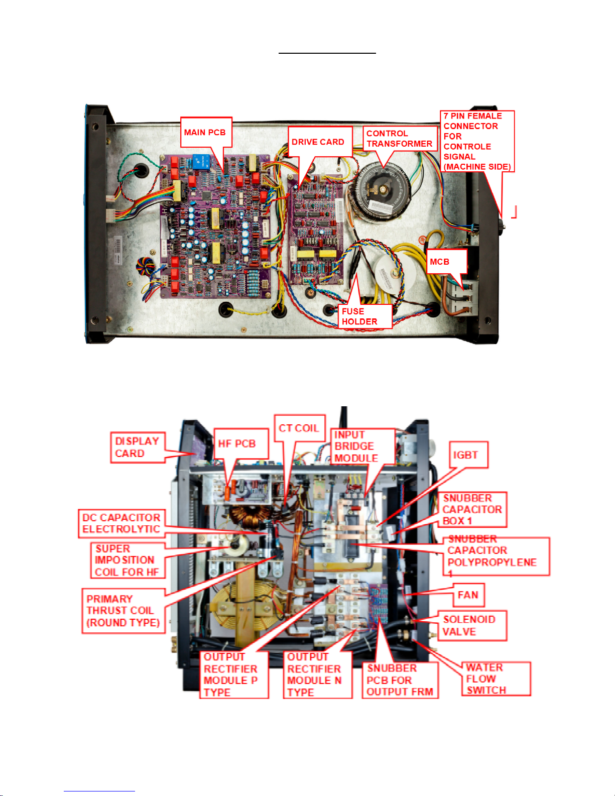
1.Top View.
2.Right si de View
Page 26

INTIG 316/501 AC/DC
-25-
3.Left sid e View
4.Front Vie w
Page 27

INTIG 316/501 AC/DC
-26-
Spare parts List for INTIG 316, 501 AC/DC.
INTIG 316 AC/DC INTIG 501 AC/DC
S.No
Description. Part Code Part Code
1
2 PIN FEMALE
CONNECTOR FOR
TRIGGER CABLE SIDE
CON-2-CM-F01 CON-2-CM-F01
2
2 PIN MALE
CONNECTOR FOR
TRIGGER MACHINE
SIDE
CON2PNM CON2PNM
3
7 PIN FEMALE
CONNECTOR FOR
CONTROL SIGNAL
(MACHINE SIDE). CON7PNF CON7PNF
4
7 PIN MALE
CONNECTOR FOR
CONTROL SIGNAL
(CABLE SIDE). CON7PNM CON7PNM
5
AC CAPACITOR
C-4UF/1000VAC C-5UF/1000VAC
6
CONTROL
TRANSFORMER
CTRXB24 CTRXB24
7
CT COIL.
CTCOIL-316 CTCOIL-501
8
DC CAPACITOR
ELECTROLYTIC
C-1000UF/400VDC C-2200UF/400V
9 DC CAPACITOR POLY
C-100UF/500VAC C-100UF/500VAC
10
DISPLAY CARD PCB-DSP-04 PCB-DSP-04
11
DRIVE CARD PCB-DRV-05 PCB-DRV-05
12
ENCODER SWITCH
KNOB.
KNOB001 KNOB001
13
FAN FAN0012 FAN005-AC240V
14
FAN CAPACITOR. CAP05 CAP05
15
FAST RECOVERY
DIODE.
FRM-MPSC2N100U60 FRM-MPSC2N100U60
16
FUSE HOLDER FUSE-HOLDER-02 FUSE-HOLDER-02
Page 28

INTIG 316/501 AC/DC
-27-
17
HALL SENSOR CS-4.0V-500A CS-4.0V-500A
18
HF PCB PCB-HF-02 PCB-HF-02
19
IGBT IGBT5012 IGBT-10012
20
INPUT BRIDGE
MODULE
IBDG007 IBDG003
21
JJ PCB PCB-ISO-05 PCB-ISO-05
22
MAIN PCB PCB-TIG-AC/DC316 PCB-TIG-AC/DC501
23
MAIN TRANSFORMER MTRXB25 MTRXB24
24
MCB MCB001 MCB001
25
O/P CONNECTOR
EURO TYPE (B) OCN-EURO-S 50 (B) OCN-EURO-S 50 (B)
26
O/P CONNECTOR
EURO TYPE (R) OCN-EURO-S 50 (R) OCN-EURO-S 50 (R)
27
OUT PUT CHOKE CHK005 CHK006
28
OUTPUT RECTIFIER
MODULE P TYPE
FRM-MPKC2CB150U60 FRM-MPKC2CB150U60
29
OUTPUT RECTIFIER
MODULE N TYPE
FRM-MPKC2CA150U60 FRM-MPKC2CA150U60
30
PRIMARY THRUST
COIL (ROUND TYPE)
THCL-P-316
THCL-P-501
31
ROTATION ENCODER C2373 C2373
32
SECONDARY IGBT IGBT-FF400R06KE3 IGBT-FZ600R12KE3
33
SECONDARY THRUST
COIL.
THCL-S-316 THCL-S-501
34
SNUBBER CAPACITOR
BOX 1
C-0.027UF/1000V
C-47UF/1200V
35
SNUBBER CAPACITOR
BOX 2
NA
36
SNUBBER CAPACITOR
POLYPROPYLENE 1
C-8UF/800VDC C-0.027UF/1000V
37
SNUBBER CAPACITOR
POLYPROPYLENE 2
NA C-0.47UF/1200V
38
SNUBBER PCB FOR
OUTPUT FRM
PCB-SNB-OUT-06 PCB-SNB-OUT-06
39
SOLENOID VALVE SV001 SV001
40
SUPER IMPOSITION
COIL FOR HF SUP-IMPOS-HF SUP-IMPOS-HF
Page 29

INTIG 316/501 AC/DC
-28-
41
THERMAL CUTOUT
SENSOR
C2373 C2373
42 WATER FLOW
SWITCH
FS-DS01AW131DH FS-DS01AW131DH
43 WIRE WOUND
RESISTOR
R-20E-200W R-20E-200W
 Loading...