

Page 1

1
INTIG 402 PULSE
OPERATING MANUAL.
Warpp Engineers Pvt Ltd.
Source of Reliable welding and cutting equipment.
Unit no 36/15 Unique Industrial Estate,
Dhumal Nagar, Waliv,
Vasai East,Palghar 401208.
TEL: 08551819944, 8551817869, 851817744.
E mail: [email protected]
Website: www.warpp.co.in
Page 2

2
1. SAFETY
Welding is dangerous, and may cause damage to you and others, so take good
protection when welding. For details, please refer to the operator safety guidelines in
conformity with the accident prevention requirements of the manufacturer.
Professional training is needed before operating the machine.
Use labor protection welding supplies authorized by national
security supervision department.The operator must be
qualified personnel with a valid "metal welding (OFC)
operations" operation certificate.Cut off power before
maintenance or repair.
Electric shock—may lead to serious injury or even death.
Install
earth
device
according
to
the
application
criteria.
Never touch the live parts when skin bore or wearing wet
gloves/clothes.Make sure that you are insulated from the
ground and work piece.Make sure that your working position
is safe.
Smoke& gas—may be harmful to health.
Keep the head away from smoke and gas to avoid inhalation
of exhaust gas from welding.Keep the working environment
in good ventilation with exhaust or ventilation equipment
when welding.
Arc radiation—may damage eyes or burn skin.
Wear suitable welding masks and protective clothing to
protect your eyes and body.Use suitable masks or screens to
protect spectators from harm.
Improper operation may cause fire or explosion.
Welding sparks may result in a fire, so please make sure no
combustible materials nearby and pay attention to fire hazard.
Have a fire extinguisher nearby, and have a trained person to
use it.Airtight container welding is forbidden
Hot work piece may cause severe scalding.
Page 3

3
Donot
contact
hot
work
piece
with
bare
hands.
Cooling
is
needed
during
continuous
useofthe
welding
torch.
Magnetic fields affect cardiac pacemaker.
Pacemaker users should be away from the welding spot
before medical consultation.
Moving parts may lead to personal injury.
Keep
yourself
away
from
moving
parts
such
as
fan.
All doors, panels, covers and other protective devices should
be closed during operation.
Please seek professional help when encountering machine
failure.
Consult the relevant contents of this manual if you encounter
any difficulties in installation and operation.
Contact the service center of your supplier to seek
professional help if you still can not fully understand after
reading the manual or still can not solve the problem
according to the manual.
Page 4
4
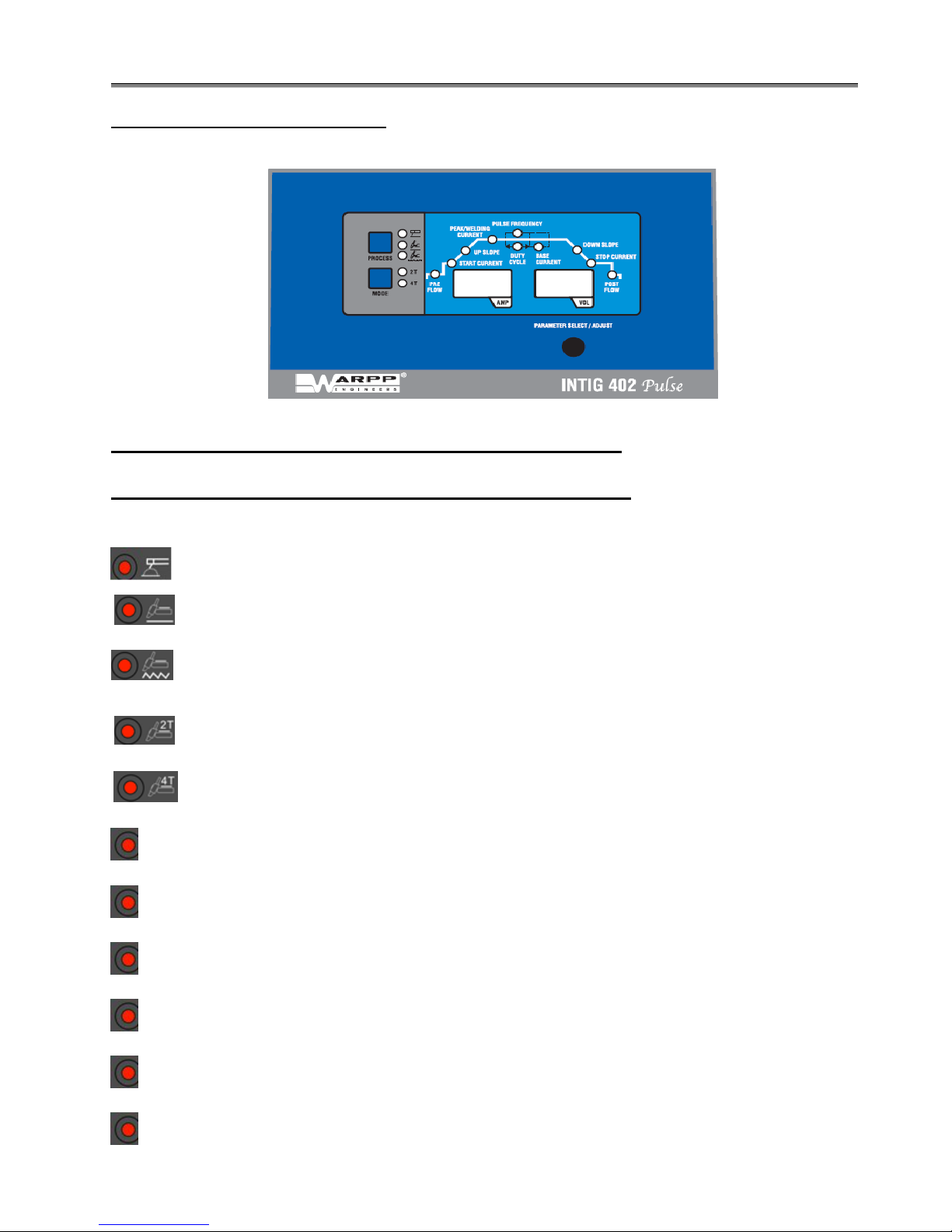
( FRONT PANEL DESCRIPTION ):
PARAMETER SETTING FOR INTIG 402 PULSE
DESCRIPITON OF INDICATION AND SWITCH :
:This LED indicates the welding is in the MMA or SMAW mode .
:This
LED
indicates
the
welding
isinthe
TIG
mode
.
:This
LED
indicates
the
welding
isinthe
PULSE
mode
.
:This
LED
indicates
the
welding
isinthe2Trackmode.
(
Applicable
only
in
TIG
Mode
).
:This
LED
indicates
the
welding
isinthe4Track
mode
.
(Applicable
only
in
TIG
Mode
)
PREFLOW :This LED indicates the preflow time before the GAS.
START CURRENT : This LED indicates the Start Current or Hand Arc welding current state
output.
UPSLOPE :This LED indicates the time taken for machine to reach it welding current from
its start current.
PEAK CURRENT :This LED indicates the Welding current during welding & arc welding
normal output state.
PULSE FREQUENCY :This LED indicates the operating frequency of PULSE output
( applicable in PULSE MODE ).
DUTY CYCLE :This LED indicates the ON / OFF TIME OF pulse frequency output.
Page 5

5
BASE CURRENT :This LED indicates the base current during off time of pulse output
( Applicable in PULSE MODE).
DOWN SLOPE :This LED indicates the time taken for machine to reach its Arc current from
its welding current.
STOP CURRENT : This LED indicated the current value before the are welding quenching.
POST FLOW :This LED indicates the continues flow timing after welding.
PROCESS :This SWITCH is used for selection of MMA , TIG Or PULSE WELDING.
MODE :This SWITCH is used for selection of 2 Tray Or 4 Tray welding.
VOLT/AMP :This is digital display for voltage and current display.
DURING WELDING
STEP -1 DISPLAY SETTING:
Connect
holder
and
earth
clamp
at
output,take
a
5 mm rod
in
holder
and
do
welding. Set output current 50A to 400A with the help with help of rotary
switch.Same procedure apply to 4 mm&3.15mm rod.
STEP -2 HF TESTING:
Put
SMAW
/
TIG
switch
in
TIG
mode
and
press
the
torch
switch
,HFspark
will be generated on the HF spark plug.
STEP -3 GAS TESTING:
Put
the
switch
in
TIG
mode
solenoid
valve
will
turn
ON.Now
press
the
torch switch and release it.Valve will turn off.
STEP -4 DOWN SLOPE TESTING:
Arc
force
/
down
slope
pot
should
be
maximum
and
in
4step
mode.When
torch switch is pass and released for to stop the welding,current will slowly
decreases to minimum and then welding will stop after 5sec.
Page 6

6
Warpp Engineers Pvt Ltd.
Source of Reliable welding and cutting equipment.
Unit no 36/15 Unique Industrial Estate, Dhumal Nagar, Waliv,
Vasai East,Palghar 401208.
TEL: 08551819944, 8551817869, 851817744.
E mail: [email protected]
Website: www.warpp.co.in
 Loading...