

Page 1

INVERTER GAS SHIELDED
MIG WELDING MACHINE
OPERATION MANUAL
WARPP ENGINEERS PVT. LTD.
B-1005, Western Edge II, Near Metro Mall, Off. Western
Express Highway, Borivali (E), Mumbai-400 066.
Tel:022-28542272 / 73/74 Fax:022-28542275.
Website:www.warpp.co.in Email:sales@warpp.co.in
Page 2

CONTENTS
Safe item........................................................................................................ (3)
Brief of product............................................................................................... (4)
Properties..................................................................................................... (5)
Assemble.......................................................................................................(6)
Operation ...................................................................................................... (8)
Welding parameter checking list...................................................................(10)
Attention ...................................................................................................... (11)
Maintain ...................................................................................................... (13)
Regular check...............................................................................................(14)
Spare Part list............................................................................................... (15)
Page 3

Safe Item
Please do the best safeguard when operator does the welding work, welding work will
be bringing the harm to you and others. Regarding the detailed information regarding
the accident when welding, please check the manual carefully.
There is necessary to have a train for the welding work operator, in order to use this
machine safely.
·using the necessary and good quality safeguard dressing.
·operator should be the person who has enough welding skill and ability to operate the
machine.
·please cut off the power connection when they maintain and repairing being in.
Electric sh o ck -------- it would be issuing the deeply harmful, even die.
·please connect and assemble depending on the application standard.
·please do not touch the electriferous elements when you keep your skin bareness,
dressing the wet gloves or wet clothes.
·please make sure that you, ground and working material would be isolated.
·please make sure your working position is in safe situation
Fume -------- may be harmful for your health
·please keep your head out of the smoke avoid to take in the welding fume.
·while welding working, please keep the ventilation running well, in order to keep the
working condition well for surrounding air
.
Arc light radiation --------- may be harmful for your eyes and burn your skin
·please use the qualified welding mask, dressing the safeguard clothes, to keep your
eyes and body in safe situation.
·please use the suitable mask and curtain to keep the onlookers in healthy situation.
Fire hazard
welding spark would issue the fire, please make sure there is no combustibles thing
·
nearby welding place, and also there is necessary to do the fire protection.
·to be making sure the fire unit near the place of welding and confirm there is at least
one person could use the fire unit
.
Noise ------------- more noise would be harmful for hearing.
·protection your ears, please wear the necessary unit to protect your ears from
harmful noise.
·please warn the onlookers, noise would hurt their hearing
.
.
Page 4
Product Brief
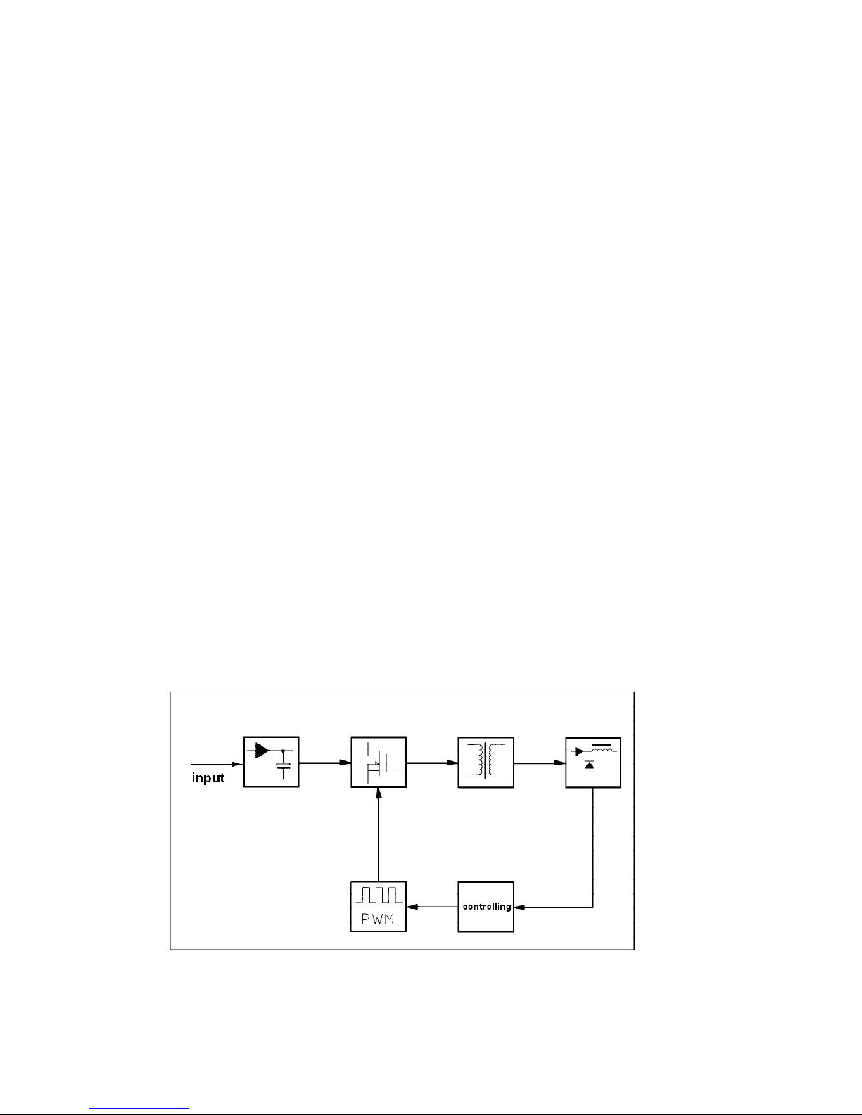
INMIG IH gas shielded welding machine is the inverter welding machine with the
international advanced inverter technology.
The general principle of it is to make the 50Hz/60Hz AC current into DC current, and
make the DC current into high frequency AC current basing on the high power
electronic element IGBT, whose frequency could be 20KHZ, reducing voltage and
rectification
Character:
1. IGBT inverter technology, current controlling model, high quality, steady
properties.
2. constant voltage output, high adaptability for electricity network (±15%)
3. electronic inductor controlling, less splash, deep weld pool and good forming
4. Hot start with slow wire feeding, welding with globule wiping off, high hot start
success rates.
5. suitable for 0.8mm thickness welding material
6. small size, light weight, simple operation
The efficiency of machine would be above 85%, and machine would be with energy
conservation function
Drawing
.
Page 5

Parameter
Input current (A)
Parameter INMIG 250 IH
Input power Three phases 380V +/-15%
50/60 HZ
14
Power capacity (KVA) 9.2
Current adjustment ra nge (A) 50-250
Output voltage (V) 15-29
Duty cycle (%) 60
Power factor 0.85
Efficiency (%) 85
No Load V oltage 55
Wire feeder model INSIDE
Post blow time (S) 1 +/-0.5
Roller diameter (mm) 270
Welding w ire diameter (m m)
Welding thickness (mm)
>0.8
Isolation class F
Protection class IP21
WEIGHT 18
Page 6
Wire connection
Assemble
Page 7

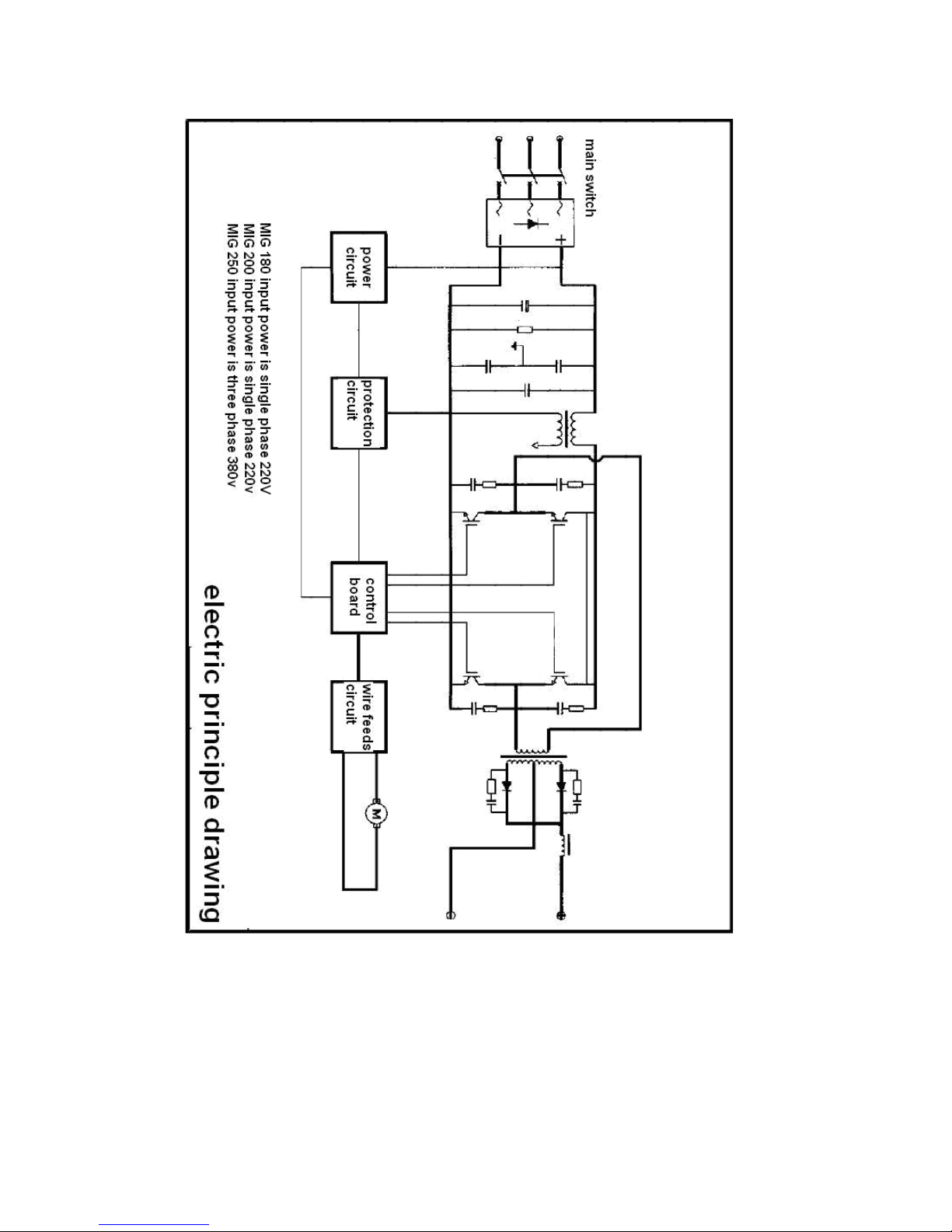
1. input wire connection
There is a power wire for each machine.
180/200’s power wire should be connecting to AC 220V; 250’s power wire should be
connecting to AC 220V, there is no phase order for three wires
2. output wire connection
.
Please connect the gas cylinder which is with the gas gauge to the CO2 enter door at
the rear of machine through gas tube.
Please connect the quick connector of grounding wire to the corresponding quick joint
of the machine; other end of grounding wire should be connecting to the working
piece.
Please connect torch to the joint of wire feeder and fasten it, and put the welding wire
into torch.
3. roller assemble
Please put the roller which is with welding wire on the axle of wire feeder; please
make sure the roller is put right and stable.
Please choose the right roll for the welding wire.
Release the the roll pinch, put the wire in groove, adjust the roll pinch to press the wire,
in order to keep the wire stable in groove, but the pressure could not be big for wire
feeding.
Roll should be running with clockwise to release the wire.
Please choose the dimension of roll basing on the dimension of wire for welding
Please touch the button to feed the wire out of torch
Page 8

Gas cylinder assemble
Please connect the gas cylinder which is with the gas gauge to the CO2 enter door at the rear
of machine through gas tube,and fasten it by gas tube lock
.
Please pay attention:
1. Please keep the gas cylinder far from high temperature area, and all possible high
temperature places, in order to avoid increasing the gas pressure for accident.
2. Please fasten the joint of gas cylinder, keep the gas not go out of cylinder.
3. Please do not kick gas cylinder and lie down the gas cylinder.
4. Please turn off the gas cylinder when there is no any person in front of the gas
gauge.
5. Please connect the heater power stock to the machine rear – 36vac connector.
6. Gas gauge should be assembled in upright situation; otherwise it cannot show the
parameter correctly.
7. Please choose the right gas gauge
8. Please keep the gas cylinder connector clean to protection the gas gauge goes
.
well
Please dressing the mask when you do the welding work.
Operation
1. Please turn on the the gas switch of welding machine, open the valve of the gas
cylinder, and adjust the gas gauge to the ideal parameter.
2. Please choose the torch tip basing on the welding wire.
3. please adjust voltage and current basing on the work piece
4. Inductance adjustment could be helpful for electric arc’ strength, soft or hard.
5. push the button of torch to begin the welding work
Welding current adjustment
Welding current and electric arc voltage would be very important for the welding
stability, welding quality and production efficiency. In order to make sure the welding
quality , please adjust the parameter of welding current and electric arc induct ance well,
usually, it would be chosen basing on the welding wire diameter and production
efficiency.
Please check the common parameter list below for the welding current and electric
arc:
Welding method Thin wire
CO2 flow
parameter
(L / min)
Thick wire
co2 welding
5-15 15-25 25-50
co2 welding
Thick wire big
current co2 welding
Page 9

CO2 welding current and voltage scope
Welding wire
diameter (mm)
0.6 40-70 17-19 160-400 25-28
0.8 60-100 18-19 200-500 26-40
1.0 80-120 18-21 200-600 27-40
1.2 100-150 19-23 300-700 28-42
1.6 140-200 20-24 500-800 32-44
Welding speed choice
Short cut transition
Current (A) Voltage (V) Current (A) Voltage (V)
submarine-launched transition
This should be adjusted for the welding quality and production efficiency. If the
welding speed was faster, protection effect would not be good, cooling speed should
be bigger, the result is the welding crack’s forming would not be good and it would not
be well for welding forming. If the welding speed was slower, it would be very easy to
burn through the work piece and to make welding crack structure bigger and more
rough. In real situation, welding speed would not be faster than 30m/hour.
Welding wire
extension length
Welding wire extension length‘s increasing would be helpful for welding wire fusion
quicken and increase the production efficiency. If the extension would be bigger,
welding wire would be very easy to welding break, bigger splash, and make the
welding process not steady. Usually, the length of welding wire should be the ten
times longer that the diameter of welding wire
.
CO2 gas flow parameter choice
Mainly considering the effect of protection. And, inside corner protection would be
better than the outside’s.
Welding parameter list
Welding current and arc voltage will be the key point for the welding stability, welding
quality and production efficiency. To keep the good welding quality, it should be a good
collocation between welding current and arc voltage. It should be choosing basing on the
diameter of welding stick and production efficiency.
The checking the list for the welding current and arc voltage for regular using
1.1 butt welding
Page 10

2.
3.
Page 11

4.
Page 12

1. Environment
(1)
The welding operation shall be operated in a relatively dry environment, and the
air humidity should not exceed 90 percent.
(2) The ambient temperature should be between -10 and 40.
(3) Do not weld under the sunlight or in the rain, and do not let water or rain go
into welding machine.
(4) Do not weld in dust or under the environment containing corrosive gases.
(5) Do not weld at the vibrant and easy-collision places.
2. Security key points
The welding machine has been installed protection circuit against over current
and overheat, which will automatically stop working when the temperature is higher
than the standard and welding machine will enter the state of protection when the flow
is excessive. But excessive use (such as welding current excessive) would have still
caused damage to the welding machine, so you need to pay attention to the
followings:
(1) To keep good ventilation!
Since the size of the welding machine is small, natural ventilation can not meet
the need of cooling it when strong current goes through it, we use a cooling fan to
make it work smoothly.
User should confirm the ventilation is not covered or blocked. The distance
between the machine and the surrounding objects must be kept no less than 0.3
meters. The user should always keep it good ventilation, which is very important to
work efficiency and service life of the machine.
(2) To prohibit electric current from overloading!
User Should observe the strongest load current (relatively to the selected load
sustained rate) at any time,so as to ensure the welding current against exceeding the
allowed maximum.
The life expectancy of welding machine will be significantly shorten,or even be
burned, by overload current.
(3) To prohibit over voltage!
The power voltage is listed in the main technique parameters such as these in
form1, in normal conditions; the voltage auto-compensation circuit in the welder limits
the welding current within normal range. If the power voltage exceeds the normal
range, the welding machine will be damaged. As a result, the operator should be fully
aware of the situation and proper protective measures should be taken.
Page 13

(4) There is one grounding screw on the back of every welder with the grounding mark.
Before use, selecting one cable with the cross section of more than 4mm2, connect
the shell of welding machine to ground to discharge electrostatic or avoid possible
accidents due to current leakage.
(5) If the welding machine exceeds the standard continuous loading time, the welding
machine would enter protective state and stop working. If this situation happens, it
indicates that the welding machine exceeds sustained rate of standard load. And
excessive heat trigger the temperature detect switch, which make the welder stop
working. At the same time, the yellow dictator at the front board goes out.
In this case, do not plug off the power so that the cooling fan starts to cool the
welding machine. When the yellow indicator lit up, it indicates the temperature lower
down to the normal range and welding work can be continued.
Maintenance
Regular maintenance and inspection are done to ensure the machine to work safely
and efficiently. Check whether the power of the welding machine is off before
checking the external connectors. Check the internal wiring five minutes after the
power of the welding machine is turned off, so that the capacitors of the machine are
fully discharged to avoid electric shock accidents and ensure the safety of the staff.
Reference Guide for Maintenance
Line maintenance items
1. The function of the power switch
2. Whether the cooling fan is
rotating normally
3. Whether the abnormal vibration,
noise or smell exists
4. Whether the cable connector is
overheated
5. Whether welded cable is
abnormally hot
6. Whether the cable is damaged
7. Whether a wire connector is loose
A regular maintenance
is done every one or two months
1. Remove dirt:
Compressed air is used to remove
dirt, in particular the dirt on inductors,
transformers, power transistors and
printed circuit boards.
2. Maintenance of the circuit
connectors
Check whether the input terminal, the
output connector, the external
connections are loose or rusty.
Tighten the loose places and remove
the rust to ensure good contact.
3. Check whether the grounding line is
well.
Page 14

The repairing principle of the welding machine should be made by our company and
the user can solve the problems met in using it under the direction of our company.
1. Issues to pay attention
(1)
It should rivet the tag of equipment number on the shut of the casing, or the inner
elements might be damaged.
(2)The connection between the welding cable and the connecting terminal of the
welding machine should be solid and reliable. Otherwise, the terminal can be burn
out which will result in the unstableness of the welding process.
(3) To keep the bare copper parts of the welding cable and the connecting terminal of the welding
machine from the metals on the ground to avoid the short-circuiting of the welding
machine output.
(4) To avoid the damage or break of the welding cables and the control cables.
(5) To avoid the deformation of the welding machine caused by being stroken. Do not
stack heavy load on the welding machine.
(6) To keep being ventilated.
2. Regular check and maintenance of the welding machine
(1)
The professional repairing staff should clean the welding power with the
condensed air for every 3- 6 months. Meanwhile, check the fastening piece in the welding
machine and no loose phenomenon should happen.
(2) check often that if the cable has been damaged and if the control knob is loose
and if the members on the panel has been damaged.
(3) Current contact nozzles and the wire feed rolls should be changed timely. The wire
feed tube should be cleaned frequently
.
3. Faults and solutions of welding machine
3.1
The following check shall be made before maintenance:
(1) Whether the position of switches on the front panel are right or not.
(2) Whether the line voltage of three-phase power is within 340V~420V; and open-phase or not.
(3) Whether the connection of welding machine power input cable is right or not.
(4) Whether the grounding line of welding machine is right and reliable.
(5) Whether the connection of welding cable is right or not, and whether the
connection is good or not.
(6) Whether the gas path is good or not, and whether CO2 gas regulator is normal or
not.
Note: The highest voltage in the welding machine reaches 600V. To guarantee
safety, it is prohibited to open the shell of welding machine at random.
When maintaining, pay attention to safety and prevent electric shock.
Page 15

FRONT VIEW
Digital Display
Meter V o ltage
(DSP001)
10K Potentiometer
for Inductance
Digital Display
Meter Current
(DSP001)
(POT004)
Output Connector
EURO Type with
Strip (OCN-EURO-S)
13 Pin Connector
Panel Mounted Female
(CON13PM
-
F)
Page 16

REAR VIEW
F
an
(FAN007)
Shunt (SHUNT-
Snubber Card
(PCB-SNB-B39)
S-300-75)
MOV (MOV001)
IGBT (IGBT5012)
Page 17

LEFT VIEW
Main
Transformer
(MTAX-B08)
Control Transformer
(CTRAX-B39)
Output Rectifier Card
(PCB-OUT-FRM001)
Page 18

TOP VIEW
Main PCB
(PCB-MIG-250 IH)
Drive Card
(PCB-DRV-04)
Capacitor Board
(PCB-CP-250 IH)
Input Bridge Module
with Surge Suppressor
Board (PCB-IB-01)
Page 19

BACK VIEW
MCB (MCB001)
Fuse Holder
Page 20

SPARE PART LIST INMIG 250 IH
DESCRIPTION Part Code
MAIN PCB PCB-MIG-250 IH
DRIVE CARD PCB-DRV-04
IGBT IGBT5012
INPUT BRIDGE MODULE WITH SURGE
SUPRESSOR BOARD
OUTPUT RECTIFIER MODULE CARD PCB-OUT-FRM001
FAN FAN007
CAPACITOR BOARD PCB-CP-250 IH
SNUBBER CARD PCB-SNB-B39
MCB MCB001
DIGITAL DISPLAY METER DSP001
CONTROL TRANSFORMER CTRAX-B39
MOV MOV001
SNUBBER PCB FOR OUTPUT FRM PCB-SNB-OUT-01
POTENTIOMETER FOR INDUCTANCE POT004
KNOB FOR THE POT KNOB001
OVERCURRENT PROTECTION PCB PCB-OC-250
MAIN TRANSFORMER MTRX005
OUT PUT CONNECTOR EURO TYPE
WITH STRIP
13 PIN CONNECTOR PANEL MOUNTED
FEMALE
13 PIN CONNECTOR MALE CABLE
SIDE
SHUNT SHUNT-S-300-75
LED GREEN LEDG01
LED YELLOW LEDY01
PCB-IB-01
OCN-EURO-S
CON13PM-F
CON13CM-M
WIRE FEEDER MOTOR WITH WIRE
FEED MECHANISM
24 V SOLANOID VALVE SV002
EURO CONNECTOR FEEDER SIDE EURO-BRASS-01
PRESUURE ARM PRARM001
PRESURE HOLDER PRHLD001
SUS TUBE SUS001
ROLER 0.8/1.0 INMIGRLR001
ROLER 1.0/1.2 INMIGRLR002
ROLER 1.2/1.6 Not Applicable
POTENTIOMETER FOR
CURRENT/VOLTAGE
INCHING SWITCH INCSW001
KNOB FOR THE POT ( Black ) KNOB002
WIRE FEED MECHANISM WITHOUT
MOTOR
WIREFEEDER
WFMTR002
POT003
WF-MECH-INMIG
 Loading...