

Page 1

COMBO-401 i /501 i
Inverter CO2/MIG/MAG Gas Shield
Welding Machines
OPERATOR’S MANUAL
(PLEASE READ CAREFELLY BEFORE OPERATION)
Page 2

COMBO-401 i/501 i OPERATOR’S MANUAL
1
Safety Depends on You
Our arc welding and cutting equipment s are designed and built with safety in mind. However, your overall safety
can be increased by proper installation.
DO NOT INSTALL, OPERATE OR REPAIR THIS EQUIPMENT WITHOUT READING THIS MANUAL AND
FOLLOWING THE SAFETY PRECAUTIONS CONTAINED THROUGHOUT.
Special Attention (Very Important):
●
PLACE THE MACHINE ON A PROPER PLANE, SO THAT THE MACHINE DOES NOT SLIP.
●
PLEASE KEEP THE MACHINE AWAY FROM RAIN ( UNDER PROPER ROOFING ).
Purchase Date:
Serial Number:
Machine Type:
Purchase Place:
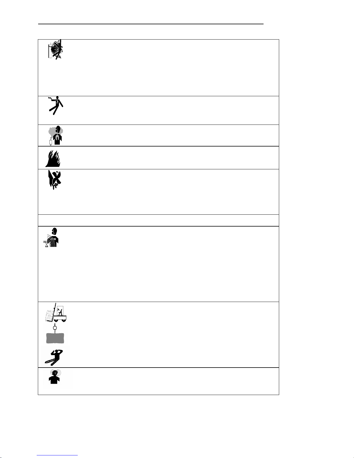
Cautions
Arc and arc rays may harm health.
Page 3

COMBO-401 i/501 i OPERATOR’S MANUAL
2
Arc welding can be hazardous. All performing welding workers ought to have health qualification
that provided by authority organization. Protect yourself and others from possible serious injury or
death. Keep children away. Pacemaker wearers should consult with their doctor before operating. Be
sure that all installation, operation, maintenance and repair procedures are performed only by qualified
individuals.
1
Electric shock can kill: The electrode and work (or ground) circuits are electrically “hot” when
the
welder
is
on.Donot
touch
these“hot”parts
with
your
bare
skinorwet
clothing,
Wear
dry,
hole-free
gloves
to
insulate
hands.
Users
needtofollow
the
below
itemstoavoid
electric
shocks:
Insulate yourself from work and ground using dry insulation. Make certain the insulation is large enough to cover
your full area of physical contact with work and ground. Otherwise, use automatic or semiautomatic welding
machines, DC welding machines as possible as you can.
In semiautomatic or automatic wire welding, the electrode,electrode reel, welding head, nozzle or semiautomatic
welding gun are also electrically“hot”.
Always
be
sure
the
work
cable
makes
a
good
electrical
connection
with
the
metal
being
welded.
The
connection
should be as close as possible to the area being welded.
Ground the work or metal to be welded to a good electrical(earth) ground.
Maintain the electrode holder, work clamp, welding cable and welding machine in good, safe operating condition.
Replace damaged insulation.
Never
dip
the
electrode
in
water
for
cooling.
Never simultaneously touch electrically“hot”parts of electrode holders connected to two welders, because voltage
between the two can be the total of the open circuit voltage of both welders.
When
working
above
floor
level,
please
do
wear
safety
belttoavoid
falling
or
losing
balance
on
electric
shock.
2
Arc rays can burn: Use a shield with the proper filter and cover plates to protect your eyes
from
sparks
and
the
raysofthe
arc
when
welding
or
observing
open
arc
welding.
Head
shield
and
filter
lens
should
conform
to
nation
standards.
Use
suitable
clothing
made
from
durable
flame-resistant
material
to
protect
your
skin
and
that
of
your helpers from the arc rays.
Protect other nearby personnel with suitable, non-flammable screening and/or warn them not to watch the arc nor
expose
themselves
to
the
arc
raysorto
hot
spatter
or
metal.
3 Fumes and Gases can be dangerous: Welding may produce fumes and gases hazardous to
health.
Avoid
breathing
these
fumes
and
gases.
While
working
in
limited
room,
use
enough
ventilation
and/or
exhaust
to
keep
fumes
and
gases
away
from
the
breathing
zone,oruse
the
respirator.
Shielding
gases
used
for
arc
welding
can
displace
air
and
cause
injury
or
death.
Always
use
enough
ventilation,especially in confined areas, to insure breathing air is safe.
Do not weld in locations near chlorinated hydrocarbon vapors coming from degreasing, cleaning or spraying
operations.The heat and rays of the arc can react with solvent vapors to form phosgene, a highly toxic gas, and
other irritating products.
Read
and
understand
the
manufacturer
’sinstructions
for
this
equipment
and
the
consumables
tobeused,
including
the material safety data sheet (MSDS) and follow your employer’s safety practices. Make sure they are asepsis
and
innocuity.
4
Spatter: Welding or cutting spatter can cause fire or explosion.
Remove
fire
hazards
from
the
welding
area.If
thisisnot
possible,
cover
themtoprevent
the
welding
sparks
from
starting
a
fire.
Remember
that
welding
sparks
and
hot
materials
from
welding
can
easilygothrough
small
cracks
and
openings
to
adjacent
areas.
Avoid
welding
near
hydraulic lines. Have a fire extinguisher readily available.
Where
compressed
gases
aretobe
usedinthe
field,
special
precautions
should
be
usedtoprevent
explosion.
When
not
welding,
make
certain
thatnoelectriferous
partistouching
the
work
pieceorthe
work
stage.
Accidental contact can create a fire hazard.
Do
not
weld
containers
or
lines,
which
are
not
proved
tobeinnocuity.
Do
not
heat,
cutorweld
tanks,
drums
or
containers
until
the
proper
steps
have
been
takentoinsure
that
such
procedures will not cause flammable or toxic vapors from substances inside. They can cause an explosion even though
they have been“cleaned”.
Spatter
might
cause
burn.
Wear
leather
gloves,
heavy
shirt,
cuffless
trousers,
high
shoes
andacap
over
your
hair
to prevent from burning by spatter. Wear the ear shield when performing sideways or face up welding. Always
wear safety glasses with side shields when being in a welding area.
The welding cables should be as close to the welding area as possible, and the short, the better. Avoid welding
cables going through the building framework, lifting chains, AC or DC cables of other welding machines and
appliances.
The
welding
current
is
strong
enough
to
damage
them
while
having
short
circuit
with
them.
Page 4
COMBO-401 i/501 i OPERATOR’S MANUAL
3
5 Cylinder may explode if damaged.
Make
sure
that
the
gasinthe
storage
cylinder
is
qualified
for
welding,
and
the
decompression
flowmeter,
the
adapter
and
the
pipe
are
allingood
condition.
Always keep cylinders in an upright position securely chained to an undercarriage or fixed
support.
Be
suretoput
the
cylinder
in
the
working
space
withnocrashorshake,
and
far
from
welding
area.
Never allow the electrode, electrode holder or any other electrically“hot”parts to touch a cylinder.
Keep your head and face away from the cylinder valve outlet when opening the cylinder valve.
Valve
protection
caps
should
always
beinplace
and
hand
tight
except
when
the
cylinder
isinuseorconnected
for
use.
6
Power: (For electrically powered welding and cutting equipment) Turn off input power before
installation,
maintenance
and
repairtoavoid
accidents.
Huanyuan
welding
equipment
isΙclass
safeguard
equipment;
please
install
the
equipment
in
accordance
with
the
manufacturer
’srecommendations
by
specific
persons.
Ground the equipment perfectly in accordance with the manufacturer’s recommendations.
7
Power:(For engine driven welding and cutting equipment)
Workinventilated
placeoroutdoors.
Do
not
add
fuel
neartofireorduring
engine
starting
or
welding.
When
not
working,
add
fuel
after
engine
is
cooling
down;
otherwise,
the
evaporation
of
hot
fuel
would
resultindangers.
Do
not
splash
fuel
outofthe
fuel
tank,
anddonot
start
the
engine
until
complete
evaporation
of
the
outside
fuel.
Make
sure
that
all
the
safeguard
equipment's
,
machine
cover
and
devices
are
allina
good
condition.
Be
sure
that
arms,
clothes
and
all
the
toolsdonot
touch
all
the
moving
and
rotating
components
including
V
belt,
gear
and
fan
etc.
Sometimes
some
partsofthe
equipment
havetobe
dismantled
during
maintenance,
but
you
still
have to keep the strongest safety awareness .
Do
not
put
your
hand
closetofans
anddonot
move
the
brake
handle
while
operating.
Please
remove
the
connection
between
the
engine
and
the
welding
equipment
to
avoid
sudden
starting
during
maintenance's
.
When engine is hot, it is forbidden to open the airtight cover of the radiator water tank to avoid hurt by the hot
vapor.
8 Electromagnetic: Welding current going though any area can generate electromagnetic, as well
as
the
welding
equipment
itself.
Electromagnetic
would
affect
cardiac
pacemaker,
the
cardiac
pacemaker
users
should
consult
one’s
doctor
first.
The
effectofelectromagnetic
to
one’s
health
is
not
confirmed,
anditmight
have
some
negative
effecttoone’s
health.
Welders
may
use
following
method
to
reduce
the
hazardous
of
electromagnetic:
a. Bundle the cable connected to the work piece and the welding cable together.
b. Do not enwind partially or entirely your body with the cable.
c. Do not place yourself between the welding cable and the ground (work piece) cable, if the welding cable is by
your left side, then the ground cable should be by your left side too.
d. The Welding cable and the ground cable are as short as possible.
e. Do not work near to the welding power source.
9 Lifting equipment: carton or wooden boxes package of the welding machines supplied by
WARPP
Engg.Thereisno
lifting
equipment
in
its
wrapper.
Users
can
moveitto
the
prospective
areabya
fork-lift
truck,
then
open
the
box.
If
there
are
rings,
the
machine
canbetransited
by
rings.
While
Our
Welding
Machine
Manufacture
reminds
users,
thereispotential
risktodamage
the
welding
machine.
Soitis
better
to
push
the
welding
machine
by
its
rollers
unless
special
situations.
Be
sure
that
the
appurtenances
are
all
removed
off
when
lifting.
When
lifting,
make
sure
that
thereisno
person
below
the
welding
machine,
and
remind
people
passing
byatany
moment.
Do not move the hoist too fast.
10
Noise: Our Welding Machine Manufacture reminds users: Noise beyond the limit (over 80 db)
can
cause
injury
to
vision,
heart
and
audition
depending
on
oneself.
Please
consult
local
medical
institution.
Use
the
equipment
after
doctor
’spermission
would
helptokeep
healthy.
Page 5

COMBO-401 i/501 i OPERATOR’S MANUAL
4
CONTENTS
1. Usage notices ------------
-------------------------------------
5
Machine
Model
&
Process
Features
&
Advantages
Usage
Safety
Environmental
Area
Input
power
conditions
Installation
diagram
Components
name
and
Function
Introductions
2. Connections --------------------------------------------------10
Connections
of
the
power
supply
cable
and
the
ground
wire
Connection
of
the
manual
welding
output
cable
Connections
of
Gas-shielded
Welding
2.3.1 Connection of the output cable
2.3.2 Connections of the power source, wire feeder and the welding torch
2.3.3 Connections of the gas cylinder and the gas adjuster
3. Directions of the manual welding mode ---------------11
4. Directions of the Gas-shielded Welding mode---------11
Checking
items
,methods
and
requests
&
preparations
before
operation
4.1.1 Wears of safeguards
4.1.2 Checking after connections
4.1.3 Operation of switches & adjustment of gas flux
4.1.4 Installation of the welding wire
4.2 Directions of the basic welding
4.2.1 Welding operation with crater function
4.2.2 Welding operation without crater function
5. Directions of prolonged output cable -----------------13
6. Technical conditions ------------------------------------- 13
6.1 Technical parameters
6.2 Instructions of keywords
6.3 Examples of welding condition
7. Working principle ----------------------------------------16
7.1 Summarize of working principle
7.2 Main electric elementary diagram
8. Troubles and troubleshooting---------------------------16
9. Packing list -------------------------------------------------19
Page 6

COMBO-401 i/501 i OPERATOR’S MANUAL
5
1. Usage Notices
1. 1 Machine Model is :
COMBO
401I/
501
I
Process
:
SMAW
GMAW
FCAW
Features & Advantages
Slow feeding speed with high open circuit voltage for better arc striking.
Unique feedback circuit for both voltage and current confirms stable welding process,less spatter good
weld bead and good adaptability for continues change in arc length.
Excellent F.T.T - Globule control circuit makes positive striking of arc.
crater current and voltage function for elimination of crater at the End of the weld.
PWM inverter technique with 20 khz operating frequency make the system much responsive.
It can be widely used in Gas-shielded welding, carbon arc air gouging and manual welding.
Usage
It is suitable for welding mild steel, stainless steel, aluminum and their alloy.
The machine can be used for all position welding with solid and flux cored wire.It can be used with Ф0.8 ,
Ф1.0 , Ф1.2 , Ф1.6 depends on model.
It can be used for manual metal arc welding with acid and basic types of electrodes.
Safety
For you and others safety, please follow the guide line mentioned below.
□ The machine have to be grounded properly.
To prevent electric shock, make sure the grounded bolt of the power source is grounded well.
□ use proper personal protection equipment.
To prevent injury of your eyes and skin from the ultraviolet radiation, strong sparks and splash, please make
sure to use proper personal protection equipment like helmet,hand gloves ,apron etc.
□ Protection against welding fume
The gases and fumes produced by welding are hazardous to health. Make sure that working space is properly
ventilated or use equipment like fume extractor for your safety.
□ The gas cylinder to be located in a fixed place or use proper trolley.
□ The machine and working area should be keep away from flammable things.
□ Prevent particles getting inside the machine and prevent cables from sharp things it may cut the cables .
□ Prevent the machine from damage by falling or hitting. Once it falls or hit, the machine cannot be used
again without professional checking.
Environmental Area
For satisfactory performance of the machine , please follow guide line mention below..
□
Keep
themachine
away
from
direct
sunlight
,
rain
and
dusty
atmosphere.
□ The environment temperature range should be -10℃~40℃.
□
Avoid
metal
particles
entering
into
the
power
source.
□
The distance between the power source and wall or other close things should be more than 30cm. The
distance between two machines should be more than 30cm.
□
Welding
area
should
be
protected
from
wind.
Page 7

COMBO-401 i/501 i OPERATOR’S MANUAL
6
I
nput Power conditions
Power supply : 380-440VAC
The fluctuation range of frequency:<±1%
The imbalance rate of three-phase voltage :<±5%
While using engine generator, the output power should be two times larger than the rated input power of
the welding power source and compensation coil is needed.
Installation diagram
Connection between welding equipment s and other equipment's (Please refer to the Figure 1).
1.8 Components name and Function Introductions (Please refer to the Figure 2)
1. Voltage meter: to indicate the actual welding voltage
2. Current meter: to indicate the actual welding current
3. Current adjustment knob: When switch 10 is placed on the manual welding position, this knob can
adjust the manual welding current. When switch 10 is placed in the gas-shield welding position, this
knob can adjust the gas-shield welding current.
4. Crater voltage adjustment knob: adjust the crater voltage.
5. Arc characteristic adjustment knob: While used as gas-shield welding, it is to adjust and control
the current changing rate in different duration of the melt drop transfer in the welding process. It will
directly influence arc’s soft and rigid characteristics, quantity of spatter, shaping of welding seam and
the stability of arc. It is advised to use standard characteristic. Adjust it to the soft characteristic while
doing as small criterion welding, and adjust it to the rigid characteristic while doing as middle and
large criterion welding. (Note: the softer arc, the less spatter, vice versa.)
6. Under voltage indicator lamp: When the distribution voltage is lower than 320VAC, it lights, and
the output current will be cut automatically. After the voltage is back to normal, the machine will
work again.
7. Over heat indicator lamp: If it runs beyond excess of its rated duty cycle, or in a high temperature
environment, the thermal sensor’s temperature achieves 75℃±5℃, the heat protection circuit will
work, and the heat indicator LED will glow, the output current will be cut off. Wait until the machine
cool down and LED turned off, you can restart the machine after that. If the entrance of the gas path
is jammed or the fan doesn’t work, the LED will also glow.
8. Power source indicator lamp: As soon as the machine start, it lights.
9. Welding mode selection switch: It is to switch the welding process from manual welding to
gas-shield welding.
10. Welding wire diameter selection switch: It is to switch the standard welding wire’s diameter to
adopt the machine. It is actually to choose the suitable welding program. Turn the switch to the
diameter matched with the welding wire.
11. Welding wire type selection switch: It is to switch the standard welding wire’s type to adopt the
machine. Turn it to the solid position while using solid welding wire; turn it to the flux-cored position
while using flux-cored welding wire.
12. Crater mode selection switch
::::
It is to determine whether fill the arc holes at the end of welding. That
means to determine whether use crater function or not.
13. Gas-supply selection switch
::::
To check gas flow, turn it to "checking" position; to weld, turn it to
"welding" position.
14. Power overload protection switch: To cut off power and protect the machine in fault condition, it is
only used for protection, you should use other power switch while installing.
15. Control signal interface: Output interface of arc striking, to control automatic welding equipments.
The rated control load ability is 3A/250VAC or 3A/30VDC.(This interface is optional)
Page 8

COMBO-401 i/501 i OPERATOR’S MANUAL
7
16. Gas heater supply : Power socket of the gas heater, its output voltage is 36VAC.
17. Fuse holder : 3A glass fuse holder.
18. Input connection line of three phase power: connect it to distribution box, the green-yellow line
should be connected to protective ground line well.
19. Adjustment knob of welding current: To adjust the welding current.
20. Adjustment knob of welding voltage: To adjust the welding voltage.
21. Manual wire feeding button
::::
Press the button, the wire feeder begins to feed wire. The speed of wire
feeding can be adjusted by the welding current adjustment knob. While using thinner wire, the
feeding speed should be slowed down to avoid distorting the wire.
Figure 1: connection between the welding equipment and other equipment s
Page 9

COMBO-401 i/501 i OPERATOR’S MANUAL
8
Page 10

COMBO-401 i/501 i OPERATOR’S MANUAL
9
2.
Connections
(The user should choose the power cables, switches, fuses and power switches as specified in table )
2.1 Connections of the power supply cable and the grounding cable
Methods and requirements
Make sure that power supply panel is off before connecting.
Do not connect with wet hands.
Do not place anything on the power supply cable.
Make sure all the connections are proper.
Connect the green-yellow wire of the three-phase input cable to the grounding wire on the switchboard
properly.
2.2 The output cable connection of manual welding
Methods and requirements:
Please make sure the power switch is off before connecting.
Connect the copper connector of workpiece cable to the ‘+’ and ‘--’ output socket that on the welding power
source. When it is negative connection,the welding electrode holder should be connected to the ‘+’. When it is
positive connection,the welding electrode holder should be connected to the ‘--’
The welding cable and workpiece should be properly connected by bolts, and have good contact.
2.3 Connections of Gas-shielded Welding
2.3.1 Connection of the output cable
Methods and requirements
Please make sure the power switch is cut off before connecting.
Connect the copper connector of wire feeder cable to ‘+’ output that on the welding power source;
Connect the copper connector of workpiece cable to ‘--’ output that on the welding power source, connect the
other side to workpiece with bolts;
Insert the aviation plug(six cores) of control cable into the control socket(six cores) of wire feeder, then tighten
the ring nut, connect the other side of control cable to wire feeder.
2.3.2 Connections of the power source, wire feeder and welding torch(please refer to figure 1)
Methods and requirements
Make sure the power switch is cut off before connecting;
Wire feeders that produced by our company are requested to match with the certain welding machine.
Otherwise the welding performance maybe bad and even damage the machine;
Insert the aviation plug(six cores) of control cable into the control socket(six cores) of wire feeder, then
tighten the ring nut;
Aim the control plug of the welding gun at the guide slot, then insert it into the control output socket (2 pins),
then tighten the ring nut. After the connector of welding torch aiming at guide slot, you can insert it completely.
And then turn 90° by clockwise rotation and tighten the bolts; Connect the gas pipe of welding torch to the gas
output connector of wire feeder, and then tighten the nuts.
2.3.3 Connections of the gas cylinder and gas adjuster
Methods and requirements
Install the gas regulator to the gas cylinder.
Connect the gas heater to the heater’s power source socket on the back panel of the machine.
Connect the gas hose of the wire feeder to the gas output connector of the gas heater.
3.
Directions
of
the
manual
welding
mode
Specification
COMBO-401 i COMBO-501 i
Switch capacity(A) 40 63
Fuse capacity(A
)
32 40
Section surface of power supply cables(mm
2
)
4 6
Section surface of grounding cables(mm
2
)
4 6
Page 11

COMBO-401 i/501 i OPERATOR’S MANUAL
10
Turn on the power switch of distribution box.
Turn the welding machine switch to the manual welding model.
Before welding, make sure the output terminal of the welding machine is connected to the welding
cable properly according to the section 2.2 above. adjusted welding current by the current adjustment knob on
the panel.
Please use proper personal protection equipment.
4. Directions of the Gas-shielded Welding mode
( Please read this manual carefully and strictly operate according to it ))))
4.1 Checking items ,methods and requests & preparations before operation
4.1.1 Wears of safeguards
a)
Wear
fur
gloves
and
safety
shoes
to
protect
the
skin
and
bare
parts;
b)
Wear
a
helmet
with
proper
shield
filter
glass
that
match
with
different
welding
current
to
protect
eyes;
c)
There
should
be
ventilation
in
the
welding
areatoprevent
breathing
the
deleterious
gas
.
4.1.2 Checking after connection:
a)
Check
out
all
the
items
according
to
the
section
2.3“Connections
of
Gas-shielded
Welding
”,make
sure
there’s no error.
b)
Check
out
all
the
items
according
to
the
section
1.6“Input
power
condition
”tomeet
all
the
requirement.
4.1.3 Operations of the switches & adjustment of gas flow.
First, turn on the welding machine;
Second, select the “gas-shield” mode on welding machine;
Third, select “welding wire’s type ” and the “welding diameter” as per requirement by respective switch to
meet the type and diameter of welding wire;
Fourth, turn the “Gas-supply” switch to “check” position;
Fifth, turn on the gas valve of the cylinder, and then adjust the knob of the flow meter slowly to meet the
value needed;
Sixth, turn the “gas supply” switch to “welding” position.
4.1.4 Installation of the welding wire
For the identification of operational components please refer to Figure 3 .
Methods and requirements
First, select proper size roller match with feeding wire, install the roller and make sure selected groove
should be outer side ;
Second, pull down the handle of wire feeder, and then lift the press-arm;
Third, install the welding wire reel to the welding wire reel’s axis, adjust the baffle of the welding wire
reel’s axis to be spread,screw down the manual nut. The out end of the wire is below. The welding wire will
comes out at clockwise rotation;
Fourth, let welding wire go through the wire rectification wheel (or guide pipe), wire feeding wheel slot, then
insert into the guide tip;
Fifth, press the welding wire with press-arm, and then pull up the handle to press the press-arm,
circumgyrate the handle with suitable strength;
Sixth, check up the tip of welding torch, whose diameter should meet the diameter of the wire;
Seventh, press “manual wire feeding” button on the control box of wire feeder, adjust “welding current
adjustment” knob for a right feeding speed. You can loosen the button until there is 15—20mm wire outside
of welding torch.
Page 12

COMBO-401 i/501 i OPERATOR’S MANUAL
11
Figure 3 : Installation sketch map of welding wire
4.2 Directions of the basic welding
Welding can be performed by the “crater” switch and welding torch switch on the panel
in two methods : a) with crater self-lock and b) without crater function.
4.2.1 Welding operation with crater function
1) Features instruction:
a)
The
main
features
of
the
welding
function
is
the
ability
to
fillupthe
hollows
when
ending
weld,
which
can be propitious to connect the start-point and end-point of the welding seam continuously;
b)
Mainly
usedinwelding
middling
thickness
plate;
c)
The
self-lock
willbecanceled
if
the
arcisstopped
for
more
than
0.5s.
2) Operation regulations
a)
Select
the4Tmode
;
b)
press
the
welding
torch
switch,
it
begins
to
feed
gas(gas
pre-flow
time).
After
feeding
gas
for
some
time, welding voltage appears, then coming into the arc starting state and begins to feed wire slowly.
After successful arc starting, the wire feeding speed will become normal, and then welding current
appears. Then you can release the welding torch`s switch, welding goes into the self-lock state.
Simultaneously, you can adjust the “welding voltage adjustment” knob and “welding current
adjustment” knob for the best welding performance;
c)
When
welding
is
finishing,
press
the
welding
torch
switch
again,
anditcome
into
crater
adjustment
state.
Then, set the crater voltage and current by adjusting the relative knobs on the welding power panel (or
adjust them to the needed values respectively in advance, commonly to the 60 ~ 70% of the normal
welding current ) , thus you can control and adjust the effect of filling up hollows at the end of welding.
Then release the welding torch`s switch again, wire feeding stops immediately, it will come back to
burn state, the welding voltage will decrease and become back burn voltage. When the welding current
becomes zero, arc quenches, gas feeding stops, and the welding finishes.
4.2.2 Welding operation without crater function (operate with welding torch`s switch
synchronously)
1) Features instruction:
a)
Press
the
welding
torch`s
switch
to
start
welding,
and
loosen
ittostop
welding
.
b)Itis
suitable
for
orientation
welding
and
spot
welding
of
thin
plate
.
c)
There
isnocrater
process.
2) Operation regulations:
a)
Select
the2Tmode
;
b) press the welding torch switch, it begins to feed gas ( gas pre-flow time ) . After feeding gas for some
Page 13

COMBO-401 i/501 i OPERATOR’S MANUAL
12
time, welding voltage appears, then coming into the arc starting state and begins to feed wire slowly. After
successful arc starting, the wire feeding speed will become normal, and then welding current appears. But
you can`t release the switch now.Simultaneously, adjust the “welding voltage adjustment” knob and the
“welding current adjustment”knob for the best performance of welding;
c) When welding is finishing, release the welding torch switch, wire feeding stops immediately, and
become back burn state, The welding voltage will decrease and becomes back burn voltage. When welding
current becomes zero, arc quenches, gas sending stops, and the welding finished.
5 . Directions of prolonged output cable
The connection cable on this series of machine is allowed to be lengthened between power source and wire
feeder, but the below regulations have to be followed.
a)
The
resistance
of
cable
will
increase
with
length
,
and
also
increase
of
the
cable
’svoltage
drop
.
Moreover,the cross section area of the cable effect the voltage drop;
b)
When
lengthening
the
cable,
get
the
cable
with
higher
cross
section
area
;
c)
When
lengthening
cable,
place
the
cable
straigh
t
don’t
make
in
coil
form
.
6 . Technique conditions
6.1 Technical parameters
TYPE
PARAMETER
COMBO-401 i COMBO-501 i
Shield rank IP21S
Rated input voltage Three-phase power 3~415VAC 50Hz
Rated input capacity 16.5KVA 26.3KVA
Gas-shield
welding
Output
current
60~400A 60~500A
Output
voltage
17~39V 17~39V
manual welding
Output
current
60~400A 60~500A
Output
voltage
22.4~34V 22.4~40V
Crater current 80~400A 80~500A
Crater voltage 17~40V 17~40V
Duty cycle 100% 100%
Rated current 400A 500A
Suited welding wire’s
diameter
Solid 0.8mm
1.0mm 1.2mm
Solid 1.0mm
1.2mm 1.6mm
Flux-cored
0.8mm 1.0mm
1.2mm
Flux-cored
1.0mm 1.2mm
1.6mm
Outline
(length×width×height)
640×290×530(mm)640×320×570(mm
)
Weight 39Kg 45Kg
* Its rated duty cycle is 60%, that means in a 10 minutes working period,the machine will run for 6 minutes
under rated welding current and rest for 4 minutes. If the Rated duty cycle is 100%,that means in a 10
minutes working period,the machine will run for 10 minutes under rated welding current without rest. If the
machine works over the rated duty cycle, the inner temperature will rise and exceed the fixed threshold. In
Page 14

COMBO-401 i/501 i OPERATOR’S MANUAL
13
order to avoid worsening the performance or even burning out the machine, there is heat protection on this
series of welding machine. When the inner temperature exceeds the set temperature, the heat protection will
shutdown the machine, the overload indicator LED glows, at this time the machine has no output. Wait until
the temperature is below the set temperature and the overload indicator LED will turned off, the machine
recovers and you can do welding again.
6.2 Crater ON function
Normally there is a small depressing at the end of the weld when welding is done at higher currents. The
depression is called crater, the arc crater are caused because of the arc force and solidification of metal in all
direction. To minimize the crater the machine has crater fill function.
Normally crater fill voltage and current set at 60 to 70 % of the welding voltage and current. When crater is
set ON ( 4 step mode ) the welding voltage and current will automatically switch to lower voltage and
current ( crater voltage and current ) at the end of the welding.
To guaranteed better arc striking every time the wire feeding is normally done at lower speed. When the
torch trigger is pressed irrespective of the current ( wire speed ) set , wire will be fed slowly and it switches
over to the set speed once the arc is struck.
What is burn-back time?
After welding, wire feeder is not stop even if the welding torch switch is shut down because of inertia. So
there will be some more wire drive out from the torch, thus the wire will stick to the workpiece, or it will
cause difficulty in arc striking next time. In order to avoid this , it is necessary to deal with welding machine
operation , so that after releasing the welding torch switch, the output voltage will still exist for a short time
to burn the wire. This process time is burn-back time. This time varies because of differences in welding
conditions, the resistance of welding feeding tube and the length of output cable.
6.3 Examples of welding condition
Data in table 1, table 2 is the reference value under the standard condition.
When welding, please correct the values according to work pieces and the welding position to get the right
welding conditions.
Page 15

COMBO-401 i/501 i OPERATOR’S MANUAL
14
Table 1:
Thicknes
s
(mm)
Length
(mm)
Wire
diameter
(mm)
Welding
current
(A)
Welding
voltage
(V)
Welding
speed
(cm/Min)
Stick
out
(mm)
Gas flow
(L/ Min)
T type welding
Slow speed
1.0 2.5~3 0.8 70~80 17~18 50~60 10 10~15
1.2 3~3.5 1.0 85~90 18~19 50~60 10 10~15
1.6 3~3.5 1.0,1.2 100~110 18~19.5 50~60 10 10~15
2.0 3~3.5 1.0,1.2 115~125 19.5~20 50~60 10 10~15
2.3 3~3.5 1.0,1.2 130~140 19.5~21 50~60 10 10~15
3.2 3.5~4 1.0,1.2 150~170 21~22 45~50 15 15~20
4.5 4.5~5 1.0,1.2 180~200 23~24 40~45 15 15~20
6 5~5.5 1.2 230~260 25~27 40~45 20 15~20
8, 9 6~7 1.2,1.6 270~380 29~35 40~45 25 20~25
12 7~8 1.2,1.6 300~380 32~35 35~40 25 20~25
High speed
1.0 2~2.5 0.8 140 19~20 150 10 15
1.2 3 0.8 140 19~20 110 10 15
1.6 3 1.0, 1.2 180 22~23 110 10 15~20
2.0 3.5 1.2 210 24 110 15 20
2.3 3.5 1.2 230 25 100 20 25
3.2 3.5 1.2 260 27 100 20 25
4.5 4.5 1.2 280 30 80 20 25
6 5.5 1.2 300 33 70 25 25
Put up weld (thin plate)
Slow speed
0.8 0.8 60~70 16~17 40~45 10 10~15
1.2 0.8 80~90 18~19 45~50 10 10~15
1.6 0.8 90~100 19~20 45~50 10 10~15
2.3 0.8 100~130 20~21 45~50 10 10~15
1.0,1.2 120~150 20~21 45~50 10 10~15
3.2 1.0,1.2 150~180 20~22 35~45
10
~
15
10~15
4.5 1.2 200~250 24~26 40~50
10
~
15
10~15
High speed
2.3~3.2 1.2
220 24 150 15 25
300 26 250 15 25
Corner weld
Slow speed
1.6 0.8 65~75 16~17 40~45 10 10~15
2.3 0.8 80~100 19~20 40~45 10 10~15
3.2 1.0, 1.2 130~150 20~22 35~40 15 10~15
4.5 1.0, 1.2 150~180 21~23 30~35 15 10~15
Page 16

COMBO-401 i/501 i OPERATOR’S MANUAL
15
Table 2:
7. working principle
7.1 Summarize of working principle
The input three-phase AC 415VAC50Hz(60Hz) is rectified and supplied to the IGBT inverter to produce 20
kHz AC. This AC is transformed by the high–frequency transformer and rectified; then goes into the output
terminal of DC power source.
7.2 Main electric elementary diagram
Please refer to appendix 1.
8. Troubles and troubleshooting
8.1 Please check with multimeter if there are any troubles:
Three-phase power should be 380 to 440 VAC, check if there is phase missing or exceeding voltage range;
Whether the fuse on the back panel of the welding machine is ok or not;
Whether the three-phase power switch at the switchboard is damaged; Whether the fuse and electrical power wire
are installed properly, Otherwise it will cause phase missing and the welding machine will work abnormally.
The control cable of the wire feeder is may be broken, check the continuity of related six pins of the connector
plugs at the both ends of the control cable , whether the welding cable is connected properly, and the workpiece is
connected tightly.
Whether the torch switch and the wire connected are damaged or open circuit; whether the nozzle, conduct tip ,
conduct tip’s seat and shunt are burned out and damaged.
Thick
-ness
(mm)
Wire
diameter
(mm)
Root
gap
G(mm)
Welding
current
(A)
Welding
voltage
(V)
Welding
speed
(cm/Min)
Wire out
(mm)
Gas
flux
(L/Min)
I type butt welding
Slow
speed
0.8 0.8 0 60~70 16~16.5 50~60 10 10
1.0 0.8 0 75~85 17~17.5 50~60 10 10~15
1.2 0.8 0 80~90 17~18 50~60 10 10~15
1.6
0.8095~10518~1945~501010~15
2.0 1,1.2 0~0.5 110~120 19~19.5 45~50 10 10~15
2.3 1,1.2 0.5~1 120~130 19.5~20 45~50 10 10~15
3.2 1,1.2 1~1.2 140~150 20~21 45~50 10
~
15
10~15
4.5
1,1.21~
1.5
170~18522~2340~501515
6 Face 1.2 1.2
~
1.5
230~260 24~26 40~50 15 15~20
Inside 1.2 1.2
~
1.5
230~260 24~26 40~50 15 15~20
9 Face 1.2 1.2
~
1.5
320~340 32~34 40~50 15 15~20
Inside 1.2 1.2
~
1.5
320~340 32~34 40~50 15 15~20
High
speed
0.8 0.8 0 89 16.5 120 10 15
1.0 0.8 0 100 17 120 10 15
1.2 0.8 0 110 18 120 10 15
1.6 1,1.2 0 160 19 120 10 15
2.0 1,1.2 0 180 20 80 15 15
2.3 1,1.2 0 200 22 100 15 20
3.2 1.2 0 240 25 100 15 20
Page 17

COMBO-401 i/501 i OPERATOR’S MANUAL
16
ATTENTIONS:
This welding machine adopts large capacity,high voltage and electrolytic capacitor filter, it can not be opened
until the three-phase power is shut down more than 10 minutes.
8.2 Common troubles and troubleshooting
Troubles Reasons Troubleshooting
1.After Turn on
power, the indicator
lamp doesn’t light,
the digital meter
doesn’t light.
1.Phase lack
;
2.Power switch is damaged
;
3.Power control fuse (3A) is blown
;
1.Check the three-phase power
;
2.Replace input power switch
;
3.Replace Power control fuses
;
2.Welding machine
does not work , the
undervoltage
indicator lamp lights
1.Phase lack;
2.Three-phase power is under voltage;
1. Check the three-phase power
to make sure it meet the
requirements of the machine
;
3. There is no output
voltage and there
is noise inner the
machine
1.The fast recovery diode of the main
circuit is damaged;
1.Check and replace the damaged
fast recovery diode;
4.Welding machine
doesn’t work,over
heat indicator lamp
lights
1.The temperature is too high;
2 . When welding ,cooler fans rotate
slowly or don’t work, which leads to
bad cooling;
3.Temperature relay is damaged;
1.Welding machine will become
normal after rest for some time;
2. Check the fans power or
change cooling fans;
3.Replace temperature relay;
5 . Welding wire
feeder works, but
there is no wire
feeding or the
feeding isn’t
stable.
1.Wire press wheel is not pressed
tightly
;
2.The type of wire feeding slot doesn’t
match the welding wire
;
3.The tip is jammed because of the
spatters
;
4.The wire feeding roller is damaged
;
5.The wire feeding tube of the welding
torch is jammed
;
6.The curving semidiameter of the
welding torch cable is too small
;
1.Press tightly
;
2. Replace wire feeder wheel
slot
;
3.Clean the spatters in the tip
;
4.Change wire feeding roller
;
5.Blow off the dust with the dry
compressed air or replace a right
one with the same type
;
6. Make the curving
semidiameter of welding torch
cable over 300mm
;
6.The feeder don’t
work after pressing
down the torch
switch or there is no
open circuit voltage
1.The control cable of the wire feeder
is broken;
2.Short circuit of welding gun switch;
3.The PCB is broken;
1.Replace the control cable;
2 . Check control wire of the
welding torch switch;
3.Repair or replace the PCB;
7.Many pores in the
welding seam
1.CO2gas is not pure
;
2.The gas flow is not enough
;
3.There is rust or oil in the welding
seam
;
4.The wind is strong when welding
;
5.The path of CO2is jammed or air
1.Use pure CO2gas
;
2.Adjust the gas flow
;
3.Clean the welding seam
;
4.The precaution against wind
should be adopted
;
5.Check the path;
Page 18

COMBO-401 i/501 i OPERATOR’S MANUAL
17
leak;
6.Valve doesn’t work;
7.The nozzle is distorted;
6.Check the voltage 24VDC of
the valve winding;
7.Replace the nozzle;
8 . Current /voltage
is out of control
1.Control cable of wire feeder is
broken
;
2.Current /voltage adjust potentiometer
is damaged
;
3.The PCB is damaged
;
1.Replace the control cable
;
2.Replace the potentiometer
;
3.Repair or replace the PCB
;
9. Wire feeding
starts without
pressing down the
welding torch switch
1.The wire connecting welding gun is
short circuit
;
2.Control cable of the wire feeder has
short circuit
;
3.The manual button of wire feeding is
damaged
;
1.Repair or change welding gun;
2 . Repair or change control
cable;
3.Change the manual button of
wire feeding;
10.The current isn’t
stable, and there is
too much spatter
1.Welding criterion is wrong;
2.The quality of wire is bad;
3 . There is rust or oil on the welding
device or wire;
4.Too much fluctuation of distribution
voltage;
5.The stick out of the wire is too long ;
6. wrong position of the wire diameter
select switch;
7.The type of wire feeding slot
doesn’t match the welding wire;
8.Problems in the protective gas;
9.Incorrect type of the tip or the
aperture of the tip becomes too big;
10 . Too much feculency in the wire
feeding tube , the resistance of the
feeding wire is too large;
11.The ground cable becomes loose;
1 . Adjust the welding criterion
again;
2.Change wire;
3.Clean the welding device and
wire;
4 . The fluctuation of the line
voltage can’t exceed ±15%;
5.The stick out should be about
10 times than the wire
diameter;
6. select a right position of wire
diameter select switch;
7 . Replace wire feeding wheel
slot;
8.Use the purer gas;
9.Replace tip;
10.Clean the wire feeding tube;
11.Fix the cable connected to the
ground tightly;
11.Gas heater frosts
1. The input power fuses of the heater
(5A) is burned ;
2. The resistance wire of the heater is
broken ;
1. Replace the fuse with the same
type
;
2. Repair or replace the heater
;
ATTENTION:
Only qualified technicians are allowed to perform troubleshooting work on the machine.If for any reason you do
not understand the test procedures or are unable to perform the tests/repairs safely, contact our service
department for technical assistance.
1
Page 19

COMBO-401 i/501 i OPERATOR’S MANUAL
18
QF1
C5
V2
SKM**GB128D
V3
SKM**GB128D
R1
100K/2W
R2
100K/2W
C10
C6
TM1
TA2
V4
V5
C2
C9
C1
C8
C3
L1
L2
C7
40n×2
L3
FU1
1.5A
EV1
风风
C4
风15V
1
Out
3
-15V
2
0V
4
TA1
TC1
18V
18V
36V
17V
380V
220V
190V
风 风风 风
2838 39
37
风 风
29
HL2HL1 HL3
KT1
3635
RP3
4.7K
风 风 风风
RP2
10K
风 风 风风
58 5655 54
303132
80.
81.
44
52515049
PV1
69.7071
72
G2 E2 G1E1G4 E4 G3E3 2425
G1
G2
G3
G4
G1G2G3G4 E1E2E3E4
E1
E2
E3
E4
1
2
3
4
5
6
7
8
9
10
11
27
13
14
15
16
17
18
19
20
21
22
23
24
25
AP1
NB-IGBT风 风 风 风 风 风
ZX7-AP4
79
68.6745
27V
27V
8V
26V
4746
风 风 风 风 风
RT1
RA
10K
RB
390/2
SB1 SB2
DA
1N4007
DB
1N4007
RC
4.7K
RP5
5K
RP4
5K
风 风 风 风
风 风 风 风
A
-
+
MG1
YV1
1 2 6 4 53
775366.83 42 78
风 风 风
42
SA1
风 风
43
82
R4
RP1
30K
风 风 风风
40 416261.
SA4SA5
63
风 风 风 风风 风 风 风 风 风
SA3
风 风 风风
65
SA2
风 风 风风
64
PA1
737475
76
V1
+ -
33 34
风 风 风风 风 风
59 60.
29
84
57
L4
26
Page 20

COMBO-401 i/501 i OPERATOR’S MANUAL
19
Picture 1- Right View.
Picture 2- Left View.
Page 21

COMBO-401 i/501 i OPERATOR’S MANUAL
20
Picture 3- Top View
Picture 4- Front View.
Page 22

COMBO-401 i/501 i OPERATOR’S MANUAL
21
COMBO I Parts List.
Combo 401I Combo 501I
S.No
Description. Part Code Part Code
1.
Main PCB PCB-COMBO-401 PCB-COMBO-501
2.
IGBT IGBT10012 IGBT10012
3.
INPUT BRIDGE MODULE IBDG007 IBDG003
4.
Output Rectifier Module. FRM001 FRM001
5.
FAN FAN002 FAN002
6.
DC CAPACITOR C-200UF/400V C-200UF/400V
7.
MCB MCB001 MCB001
8.
DIGITAL DISPLAY METER FOR
CURRENT & VOLTAGE.
DSP005 DSP005
9.
THERMAL CUTOUT SENSOR C2373 C2373
10.
Snubber PCB. PCB-SNB-OUT-05 PCB-SNB-OUT-05
11.
CONTROL TRANSFORMER CTRAX-B68 CTRAX-B68
12.
MAIN TRANSFORMER MTRXB68 MTRX-B68
13.
FAN CAPACITOR CAP05 CAP05
14.
HALL SENSOR CS-500A/4V CS-500A/4V
15.
Snubber Capacitor C-8UF/800VDC C-4UF-500 VDC
16.
Snubber capacitor box C-0.027uF-1KV C-0.027uF-1KV
17.
LED INDICATOR
LED-R-5MM, LED-Y-5MM,
LED-G-5MM
LED-R-5MM, LED-Y-5MM,
LED-G-5MM
18.
Panel Switch
PSW001 PSW001
19.
Wire wound Resistor R-0.5OHMJ R-0.5OHMJ
20.
Wire wound Resistor
R-1KJ R-1KJ
21. 6 Pin Connector (F) machine
side. CON-6PNF CON-6PNF
22.
AC CAPACITOR
CAP003 CAP003
23. POTENTIOMETER FOR
CURRENT
POT001 POT001
24. POTENTIOMETER FOR
CRATER VOLT
POT004 POT004
25. POTENTIOMETER FOR
INDUCTANCE
POT-33K POT-33K
26.
OUT PUT CHOKE CHK001 CHK001
27.
SECONDARY THRUST COIL
THCL-S-501 THCL-S-501
28.
O/P Connector OUTCON001 OUTCON001
29.
Snubber PCB FOR Output FRM PCB-SNB-OUT-05 PCB-SNB-OUT-05
Page 23

COMBO-401 i/501 i OPERATOR’S MANUAL
22
WIRE FEEDER DETAIL
Combo 401I Combo 501I
S.No
Description. Part Code Part Code
1.
Wire feeder Motor WFMTR002 WFMTR002
2.
SOLENOID VALVE
SV002 SV002
3.
6 PIN CONNECTOR (M) CON-6-CM-M-01 CON-6-CM-M-01
4.
POTENTIOMETER FOR
WELDING VOLTAGE
POT001 POT001
5.
POTENTIOMETER FOR
WELDING CURRENT
POT001 POT001
6. INCHING SWTTCH INCSW001 INCSW001
7. SPOOL HOLDER SPOOL HOLDER-001 SPOOL HOLDER-001
Head Office : -
Warpp Engineers Pvt Ltd.
Manufacturers of Welding And Related Plasma Products.
Unit no 5 & 6, Rajprabha Meenakshi Industrial Estate no 3,
Near Mohan Bhagat School, Naik Pada, Waliv Phata,
Vasai (E). District Palghar. Pin-401208.
TEL: 08551819944, 8551817869, 851817744.
E mail: sales@warpp.co.in
Website: www.warpp.co.in
 Loading...