

Page 1

AIRCUT 100I/161IW/200IW
INVERTER AIR PLASMA CUTTING MACHINE
OPERATING MANUAL
(PLEASE READ IT CAREFULLY BEFORE OPERATION)
Warpp Engineers Pvt Ltd.
Source of Reliable welding and cutting equipment.
Unit no 36/15 Unique Industrial Estate,
Dhumal Nagar, Waliv,
Vasai East,Palghar 401208.
TEL: 08551819944, 8551817869, 851817744.
E mail: sales@warpp.co.in
Website: www.warpp.co.in
Page 2

AIRCUT
-10
1I,161IW,
200
IW
Inverter Plasma Cutting Machine
WARPP ENGINEERS PVT LTD
1
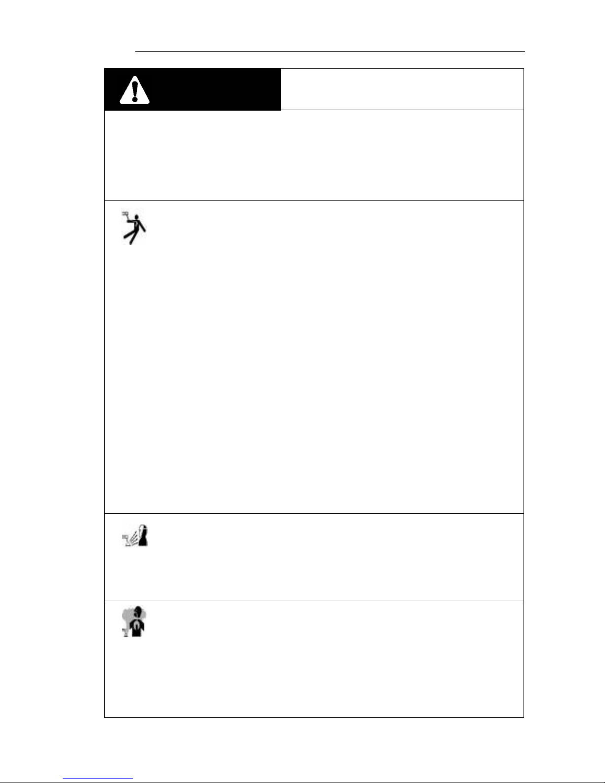
Safety Depends on You
Warpp Engineers Pvt Ltd arcwelding andcutting equipment's aredesigned andbuilt with ample safety consideration.
However, proper
installing and operating can ensure your safety.
DO NOT INSTALL, OPERATE OR REPAIR THIS EQUIPMENT CASUALLY WITHOUT READING THIS MANUAL THROUGHOUT.
Special Notes(Very Important):
1.
Pay
attention
to
avoiding
the
machine
falling
down
when
itisplaced
on
the
gradient
ground.
2.Itis
forbidden
to
unfreeze
the
pipeline
by
the
cutter.
3.
The
shield
rankofthis
series
of
cutter
is
IP21S,
so
working
in
rainisnot
suitable.
4.Thecutter has external static characteristic with rated duty cycle 100%, which means the machine can
work continuously at the rated cutting current. The machine has the function of thermal protection. When
the internal temperature exceeds a set temperature, thermal protection moves on and the abnormity
indicator lamp on the panel turns ON, then there is no output in cutter. The machine can become normal
and work only after the internal temperature drops down and the abnormity indicator lamp on the panel
turns OFF.
Purchase Date
:
Serial Number
:
Machine Model
:
Purchase Place
:
Page 3
AIRCUT
-10
1I,161IW,
200
IW
Inverter Plasma Cutting Machine
WARPP ENGINEERS PVT LTD
2
Ca u t i o n s
Arc and arc rays can hurt.
All performing welding workers ought to have health qualification from the authority organization to
prevent you and others from arc radiation and burn. It should be prevented for children to enter into
dangerous area as well.
Becareful reading thefollowing important items andthe welder safety bye law from the authority
organization. Be sure that qualified professionals perform all installation, maintenance's and repair
procedures.
1Electric shock
:The welding circuits arenot insulated when welding. Ifyou touch the
two output electrodes of the machine with your bare skin at the same time, it will lead
toelectric shock, sometimes evenfatal dangers.Usersneed to follow the items below to
avoid electric shocks:
If possible, lay some insulating materials, which are dry and large enough, in your working
field. Otherwise, use the automatic or semiautomatic welding machine, DC welding machine as
possible as you can.
Components
in
the
automatic
and
semiautomatic
welding
machine
suchasthe
welding
wire
reel, feed wheel, contact tip and welding head are all electric components. .
Always
be
sure
the
machine
has
been
connected
perfectly
to
the
work
piece
with
the
work
cables and should be as close as possible to the working area.
The
work
piece
should
be
grounded
perfectly.
Make sure that the insulating material of the electrode holder, the grounding clamp, the
welding cable and the welding head are not affected by damp, mildewed or spoilt, and be replaced
momentarily.
Never
dip
the
electrode
in
water
for
cooling.
Never touch electric components oftwo welding machines at thesame time, because this
voltage is supposed to be two times of welding voltage while the grounding mode is not clear.
While
working
high
above
the
ground
or
other
places
having
the
riskoffalling,
please
be
sure
to wear safety belt to avoid losing balance caused by electric shock.
2 Arc
: Use an arc welding mask to protect your eyes and skin from sparks and the rays of
thearc,pay special attentiontothefilter glass,whichmust be conformabletothe
national standard.
Use
clothing
made
from
durable
flame-resistant
material
or
sailcloth
to
protect
your
skin
from hurting by the arc rays.
Remind
other
nearby
personnel
before
working
lest
arc
rays
hurt
them
by
accident.
3Fumes and Gases
:Welding may produce fumes and gases hazardous tohealth. Avoid
breathing these fumes andgases. While working in limited room,use enough ventilation
and/orexhaust tokeep fumesand gasesaway from the breathingzone, oruse the
respirator. Do not weld at the same time when using of degreasing, cleaning or spraying operations.
The heat and rays of thearc can react with thesegases to form phosgene, ahighly toxic gas,
Some
protective
gases
usedinwelding
might
displace
the
oxygen
in
the
air,
and
can
leadtohurt
or even death.
Read
and
understand
the
manufacturer
’sinstructions
for
this
equipment,
and
validate
the
Page 4
AIRCUT
-10
1I,161IW,
200
IW
Inverter Plasma Cutting Machine
WARPP ENGINEERS PVT LTD
3
health certification of consumptive materials, make sure they are innocuous.
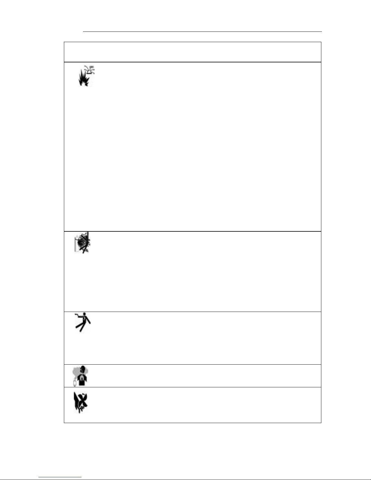
4 Spatter
: Spatter can cause fire or explosion.
Remove fire hazards from the welding area. Remember that spatter from
welding can easily go through small cracks and touch fire hazards. Protectall kinds
of lines going though welding area, including hydraulic lines in the wild.
Where compressed gases are to be used in the field, special precautions should be used to
prevent explosion.
When
welding
stops,
make
certain
thatnolive
partistouching
the
work
piece
or
the
work
stage. Accidental contact can create a fire hazard.
Do
not
weld
containers
or
lines,
which
are
not
proved
tobeinnocuous.
It is very dangerous to heat, cut or weld tanks or containers at entry holes. Does not start
work until the proper steps have been taken to insure that there is no flammable or toxic gas.
Spatter
might
cause
burn.
Wear
leather
gloves,
heavy
shirt,
cuffless
trousers,
high
shoes
and
a
cap over your hair to prevent from burning by spatter. Wear the ear shield when performing
sideways or face up welding. Always wear safety glasses with side shields when being in a welding
area.
The
welding
cables
should
beasclose
to
the
welding
areaaspossible,
and
the
short,
the
better. Avoid welding cables going through the building framework, lifting chains, AC or DC cables
of other welding machines and appliances. The welding current is strong enough to damage them
while having short circuit with them.
5 Cylinder
: Damage of it might cause explosion.
Make sure that the gas in the storage cylinder is qualified for welding, and the
decompression flow-meter, the adapter and the pipe are all in good condition.
Make
sure
that
the
installation
of
cylinder
isbythe
wall
and
bundled
tightly
byachain.
Be sure to put the cylinder in the working space with no crash or shake, and far from welding
area.
Itisforbidden
to
touch
cylinder
with
the
welding
clamp
or
the
work
cables.
Avoid
facing
the
cylinder
while
installing
the
decompression
flow-meter
or
the
gasometer.
When
not
working,
please
tighten
the
valve.
6 Power
: (For electrically powered welding and cutting equipment) Turn off input power
before installation, maintenances and repair, so that avoid accident.
Warpp
Engineers
Pvt
Ltd
welding
equipment
isΙclass
safeguard
equipment; please install
the equipment in accordance with the manufacturer’s
recommendations by specific persons.
Ground
the
equipment
perfectly
in
accordance
with
the
manufacturer
’srecommendations.
7 Power:(For engine driven welding and cutting equipment)
Work
in
ventilated
place
or
outdoors.
Donot addfuel nearto fire or during engine starting orwelding. When not
working, add fuel after engine is cooling down; otherwise, the evaporation of hot fuel
would result in dangers. Do not splash fuel out of the fuel tank, and do not start the
engine until complete evaporation of the outside fuel.
Page 5

AIRCUT
-10
1I,161IW,
200
IW
Inverter Plasma Cutting Machine
WARPP ENGINEERS PVT LTD
4
Make sure that all the safeguard equipment, machine cover and devices are all in a
good condition. Be sure that arms, clothes and all the tools do not touch all the
moving and rotating components including V belt, gear and fan etc.
Sometimes having to dismantle some parts ofthe device during maintenance, butmust keep
safety awareness strongly every time.
Do
not
put
your
hand
close
to
fans
anddonot
move
the
brake
handle
while
operating.
Please
remove
the
connection
between
the
engine
and
the
welding
equipment
to
avoid
sudden starting during maintenance.
When
engine
is
hot,itis
forbidden
to
open
the
airtight
cover
of
the
radiator
water
tank
to
avoid hurt by the hot vapor.
8 Electromagnetic
: Welding current going though any area can generate
electromagnetic, as well as the welding equipment itself.
Electromagnetic
would
affect
cardiac
pacemaker,
the
cardiac
pacemaker
users
should consult one’s doctor first.
The
effect
of
electromagnetic
to
one’s
health
is
not
confirmed,
soitmight
have
some
negative effect to one’s health.
Welders
may
use
following
method
to
reduce
the
hazardous
of
electromagnetic:
a.
Bundle
the
cable
connected
to
the
work
piece
and
the
welding
cable
together.
b.Donot
enwind
partially
or
entirely
your
body
with
the
cable.
c.
Do not place yourself between the welding cable and the ground (work piece) cable, if the welding
cable is by your left side, then the ground cable should be by your left side too.
d.
The
Welding
cable
and
the
ground
cable
areasshort
as
possible.
e.Donot
work
near
to
the
welding
power
source.
9Lift Equipment
:carton orwooden boxes package the welding machines supplied by
Warpp Engineers Pvt Ltd
.There is no liftingequipment in its wrapper. Users
canmove it tothe prospective area by a fork-lift truck, and then open the box.
If
having
rings,
the
machine
canbetransited
using
rings.
While
Warpp
Engineers
Pvt Ltd. Welding Machine Manufacture reminds users, there is possible risk to
damage the welding machine. It isbetter topush the welding machine moving in
use ofits rollers
unless special situations.
Be
sure
that
the
appurtenances
are
all
removed
off
when
lifting.
When lifting, make sure that there is no person below the welding machine, and
remind people passing by at any moment.
Do
not
move
the
hoist
too
fast.
10 Noise
: Warpp Engineers Pvt Ltd,Welding Machine Manufacture reminds users:
Noise beyond the limit (over 80 db)can cause injury to vision,heart andaudition
depending ononeself.
Please consult local medical institution. Use the equipment with doctor’s permission
would help to keeping healthy.
Page 6

AIRCUT
-10
1I,161IW,
200
IW
Inverter Plasma Cutting Machine
WARPP ENGINEERS PVT LTD
5
CONTENTS
Summary
.......................................................................................
6
Safety
and
Attention
..................................................................
7
Work
Environment
Conditions
..................................................
8
Technical
Parameters
...............................................................
8
System
instruction
......................................................................
9
Installation
and
operation
.........................................................
10
Cutting
technology
instruction
.................................................
19
Maintenance
...............................................................................
21
Troubleshooting
and
Repair
....................................................
21
Packing
list
................................................................................
23
Attached
figure
.........................................................................
24
Page 7

AIRCUT
-10
1I,161IW,
200
IW
Inverter Plasma Cutting Machine
WARPP ENGINEERS PVT LTD
6
Summary
Model
description
AIRCUT - □□□
I /IW
GAS / WATER COOLED.
Rated cutting current
Air-medium
Cutting
Plasma arc cutting machine
Features
AIRCUT-101I/161IW/200IW inverter air plasma cutting machine is a new
generated
cutter of our company. It has good characteristics as following:
1)
This
cutting
machine
adopts
IGBT
inverter
technology
which
has
high
reliability
and efficiency. It is light weight.
2)
Pre-set
current
function.
Step-less
adjustable
cutting
current,
suitable
for
cutting
various thickness work-piece. To ensure cutting quality and save energy, low
current is applied to cut thinplate, and high current isapplied to cutthick plate.
3)
External
and
dynamic
characteristics
cutter
are
significantly
better
than
leakage-reactancetyped cutter. High success rate in striking arc. Stable cutting current.
Goodarcstiffness.Cleanandsmoothincision.Excellenttechnologyperformance.
4)Ithas
the
function
of
ascending
current
slowly,
which
can
effectively
extend
the
work life of wearing parts and cutting torch.
5)
Quite
suitable
for
CNC
automatic
cutting
and
has
all
signal
output
which
is
required by CNC control.
6)
The
cutting
current
is
very
stable
anditwill
notbeinfluenced
by
grid
voltage
fluctuation.
7)
100%
duty
cycle.
It
can
work
continuously
under
max
current.
8)
Have
over/
under
voltage
and
phase
missing
protection
function.
Usage
It is suitable for cutting kinds of metal materials like low carbon steel, alloy steel
and non-ferrous metal and is widely applied in the manufacturing of boiler pressure
container, chemical container, industrial power station construction, metallurgy,
aerospace industry, automobiles, building an so on.
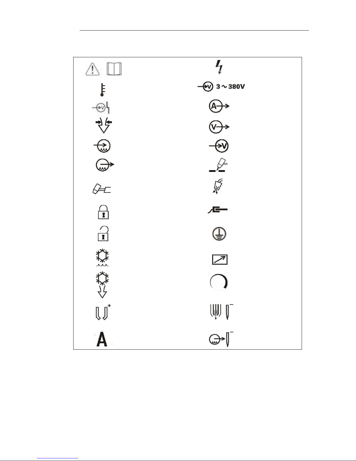
Symbol
instructions
Page 8
AIRCUT
-10
1I,161IW,
200
IW
Inverter Plasma Cutting Machine
WARPP ENGINEERS PVT LTD
7
There are below symbols on this machine.
Coolant
liquid
and
torch electrode
Current
Plasma
gas
and
torch electrode
nozzle
of
The
connection
plasma torch
Increase/
Decrease
Air
cooling
Remote
control
Water
cooling
Protection
ground
lead
Unlock
Ground
lead
Lock
Check
gas
Plasma
torch
Cutting
liquid
Voltage
input
liquid
Coolant
input
Coolant
output
Voltage
output
Air
pressure
Output
current
Power
abnormal
Input
voltage
Over-heat
Dangerous
voltage
Read
the
manual
carefully
Page 9

AIRCUT
-10
1I,161IW,
200
IW
Inverter Plasma Cutting Machine
WARPP ENGINEERS PVT LTD
8
Safety andattention
Please follow the notes for the safety of you and others.
It is forbidden to unfreeze the pipe line by cutting power or other usages except
for cutting.
The
cutter
casing
should
ground
reliably.
Please
make
sure
the
grounding
bolts
of power ground reliably in case of electric shock.
Cutter
is
the
equipment
with
high
voltage.
Please
wear
insulated
protective
shield when cutting.
When
exchanging
torch
and
wearing
parts,
please
turn
off
the
supply
power
first.
Protective
shield
should
be
worn.
In order to avoid any hurt to eyes from ultraviolet radiation and strong light and
to skin from spatter, please wear protective shield according to related rules and
regulations of labor protection.
Itisforbidden
to
inhale
harmful
gases.
The fumes and gases produced during cutting is hazardous to health. Please
wear protective shields and install aerator according to related rules and
regulations of labor protection.
Cutting
cannot
proceed
in
closed
container.
The
work-piece
just
after
being
cutisat
high
temperature.
Please
prevent
from
scald.
Protective gas cylinder and air compressor must be placed in a fixed position
and prevented from collision.
Cutter
and
cutting
place
should
be
far
away
from
flammable
materials.
Prevent foreign bodies from entering inside the machine. And protect the cable
from sharp materials.
Protect
the
machine
from
fallorcollision.
In case of fall or collision, it can be used only after professional checking.
In the surface or inside of the cutting work-piece, there should be no flammable
and explosive materials or chemical materials harmful to human.
Installation and repair person must have state-authorized electrician operation
certificate.
Cutting
operation
person
should
read
this
manual
carefully
and
know
the
operation method well.
Working Environment Requirements
1、 Environmental condition
Please use the machine in a clear place without any of dust, corrosive gas and
inflammables and explosives; Do not use it in open air and rain;
Page 10
AIRCUT
-10
1I,161IW,
200
IW
Inverter Plasma Cutting Machine
WARPP ENGINEERS PVT LTD
9
Required air relative humidity should ≤90%(at 20℃),40℃≤50%(at 40℃)
;
Environment temperature range should be at-10
℃~40℃
;
The
coolant
liquid
can
notbefrozen
when
use;
Any metal materials can not be put on or insider the power source;
Keep the machine away from the wall of some other closure things at least 30cm,
two machines distance at least 30cm.
Use it under altitude lower than 1000m.
2、 Power supply condition
1)
Power supply:3~380V/50Hz;
2)
Voltage fluctuation range<±10%
;
3)
Frequency fluctuation range<±1%
;
4)
Unbalance rate of three phase voltage <±5%;
5)
When
use
engine
generator:
the
output
power
of
the
generator
have
tobe2
times higher than the rated power of the plasma power source, with
compensating coil;
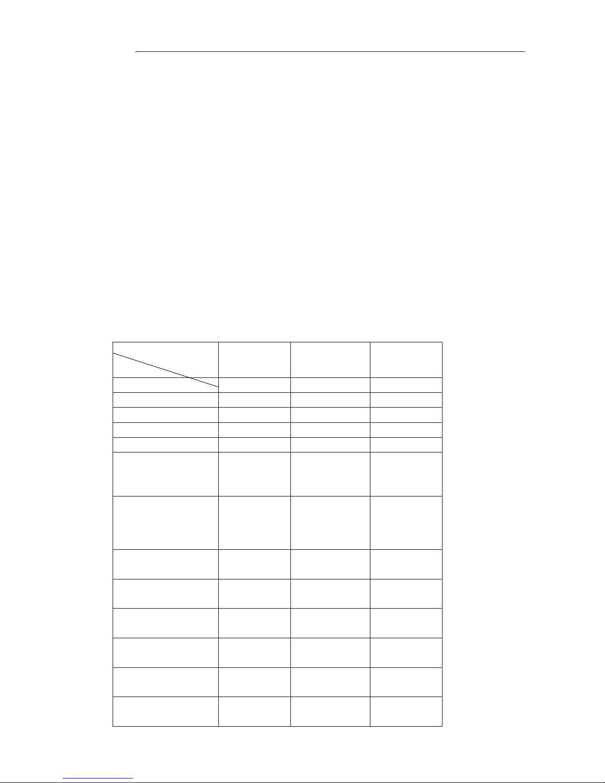
Technical parameters
1 Main technical parameters
Model
Parameter
AIRCUT
-
101W
AIRCUT
-161
IW
AIRCUT
-200
IW
Rated input capacity
17.8 KVA 32.2KVA 46.5KVA
Rated output current
100A 160A 200A
Rated output voltage
120V 144V 160V
Rated duty cycle 100%
Current adjust range
30~100A 40~160A 40~200A
Qualitycutting thickness
(Manualtype for
Carbon Steel)
0.3~22mm 1~35mm 1~45mm
Quality cutting
thickness
(Machine type for
Carbon
Steel)
0.3~12mm 1~18mm 1~25mm
Max.cutting thickness
(Carbon Steel)
40mm 55mm 65mm
Plasma gas
Compress
ed air
Compressed
air
Compressed
air
The working plasma gas
pressure
0.4~0.6MPa 0.4~0.6MPa 0.45~0.6MPa
Open circuit voltage
300VDC 315VDC 315VDC
Rated input voltage.
3~380V/50Hz 3~380V/50Hz 3~380V/50Hz
Torch cooling mode Air cooling
Air cooling
/
Water cooling
Air cooling
/
Water cooling
Page 11

AIRCUT
-10
1I,161IW,
200
IW
Inverter Plasma Cutting Machine
WARPP ENGINEERS PVT LTD
10
Arc striking mode Non-contact
Insulation grade
F
Page 12

AIRCUT
-10
1I,161IW,
200
IW
Inverter Plasma Cutting Machine
WARPP ENGINEERS PVT LTD
10
Protection grade
IP21S
Dimension mm
(L×W×H)
695×320×580
695×320×580
800×380×610 800×380× 810
NET WEIGHT 51kg 52kg 73kg 82kg
2、 Plasma gas condition
Gas pressure range:0.5MPa~0.7MPa
Gas supply pipe compression strength:≥1MPa
Gas supply pipe inner dimension:≥Φ8
Gas flow:≥180L/min
Filter
the
water
in
the
gas,
then
feed
into
the
plasma
3、External characteristic curve
U
315V
285V
100A
120A 160A
I
200A
System instruction
Working
principles
The control circuit of this cutting machine adopts advanced electronic part IGBT
as the main inverter switch component. Three-phase AC power is converted to
20KHz high-frequency DC current after being rectified by three phase rectifier. Then
under the function ofIGBT inverter the DC current is inverted to AC high frequency
current,which is invertedto DCcurrent afterexperiencingvoltage reduction inhigh
frequency transformer,current rectifying in fast recovery diode. This DC current is
filtered through reactor, and the output cutting current is obtained. Control circuit
can control output current by controlling driven pulse width. The real time cutting
current, which is obtained through current sensor connected to output terminal in
series, is used as negative feedback control signal. After comparing with current
adjusting signal, the negative control signal is sent to PWM adjusting integrated
circuit, then acontrolled driving pulse is output to control IGBT.Thereby aconstant
output current can be maintained, and a steep dropping & constant current external
characteristic is obtained. Striking arc adopts high-frequency striking model. The
main circuit refers to appendix figure, and principle diagram of control circuit is
160A/144V
200A/160V
100A/120V
120A/128V
Page 13

AIRCUT
-10
1I,161IW,
200
IW
Inverter Plasma Cutting Machine
WARPP ENGINEERS PVT LTD
11
shown as below figure .
Installation andoperation
1、 Moving and lifting
Power
source
should
be
shut
off
before
moving
the
cutter;
The cutter bottom shouldbe kept downwards during transportation. It is forbidden
to have cutter placed transversely or upended;
When
lifting,
it
must
be
lifted
vertically;
During thelong-distance transportation, it must prevent thecutter from raining and
moving back and forth inside box. Shock absorption foam should be placed around
cutter.
2、 Open the packing and check
Check
the
machine
and
packing
according
to
the
packing
list,ofthere
is
any
damage,
please
trytocontact
the
supplier.
3、 The fix and installation of the plasma power source
The mounting hole size of the automatic machine use plasma cutting machine
(
AIRCUT
-101I )
Page 14

AIRCUT
-10
1I,161IW,
200
IW
Inverter Plasma Cutting Machine
WARPP ENGINEERS PVT LTD
12
The mounting hole size of the automatic machine use plasma cutting machine
(
AIRCUT
-161IW )
The mounting hole size of the automatic machine use plasma cutting machine
(
AIRCUT
-200IW )
Page 15

AIRCUT
-10
1I,161IW,
200
IW
Inverter Plasma Cutting Machine
WARPP ENGINEERS PVT LTD
13
φ
8.2
7
5
φ
11535
65.5
4、 The connection of three phase input cable
1)
The
installation
have
to
accord
with
related
standard,
and
operate
by
professional
persons;
2)
Shut off the breaker of power, the connection operation only be allowed after
turning off;
3)
This machine use 3 phase 380V, 50Hz, user have to prepare relevant distribution box,
air breaker and power cables. The power condition as the below sheet:
Model The sectional area of
inputcopper cable (mm2)
The sectional area of
ground cable (mm2)
Fuse (A)
Contact capacity
(A)
AIRCUT
-
10
1I
≥6 ≥6 60 63
AIRCUT
-
160I
W
≥10 ≥10 80 80
AIRCUT
-
200I
W
≥16 ≥16 125 125
4)
The connection of power lead
Use eligible cables and sockets to connect it, and must be operated by a
qualified electrician.
5)
Connection
of
ground
cable
Connect the green-yellow wire of power source cable to ground ( Model
AIRCUT
-101I please connect it to ground on marking
of the machine
body) , the sectional area must match the requirements in above form, to ground
firmly. Ground connecting method should follow state standard.
4
3
29
Page 16

AIRCUT
-10
1I,161IW,
200
IW
Inverter Plasma Cutting Machine
WARPP ENGINEERS PVT LTD
14
5、The connection of compressed air and the operation of pressure regulating
filter
(Thefunctionof pressureregulatingfilterplease check thebelow figure)
Gas pressure
regulating valve
Hoop
Inlet pipe
Draining water tip
1)
The compressed gas should meet the requirement mentioned in point “Plasma gas
conditions”. Connect the gas pipe with the gas inlet of air filter on the back panel
and hoop ittightly.
2)
Theusage ofpressure regulatingfilteris as follows.When itis toadjustpressure, lift
upair pressureregulating valve, androtate it.Left rotationaims to reduceoutlet gas
pressure, right rotation aims to increase outlet gas pressure. After the gas pressure
is adjusted properly, press down regulating valve.
3)
The air filter regulator should be checked periodically. If the water level reaches
two-thirds of filter glass, it must be drained, or this will affect incision quality. The
gas supply valve should be closed during water draining, and Gas Checking function
is selected in panel. When the indicated valve of gas pressure meter is zero, water
will drain out from drainage mouth automatically.
6、 Connection of cooling water (
AIRCUT
101 I does not have this function)
Connect
the
copper
nozzle
marked
with
“
water
inlet
”onthe
cutter
rear
side
with
water supply pipe, and tighten it. Connect the copper nozzle marked with
“Backwater” with water recycle pipe, and tighten it.
Notes: when use gas cooling torch, the torch selection switch on panel must be set
to air-cooled torch position, and the cooling water cannot be connected with. The
cooling water is for cooling torch only,and cutter power source does not need water
cooling.
7、 The connection of output terminal
1)
The
connection
of
torch
The torch model matched to plasma power source is as below:
Model
AIRCUT
101I
AIRCUT
-
161 IW
AIRCUT
-
200IW
Torch
model
P80
Air cooling
160
Water cooling
200
Water cooling
Remarks
Also work with P80 under 120A
current
Page 17

AIRCUT
-10
1I,161IW,
200
IW
Inverter Plasma Cutting Machine
WARPP ENGINEERS PVT LTD
15
The selection of torch nozzle
Thebest current rangefor different nozzlesis different. Pleaseselect the
nozzle according to below form.
Nozzle aperture
diameter (mm)
1.0 1.2 1.4 1.6 1.8 2.0 2.2 2.4 2.6
Suitable current
(A)
20~30 30~40 40~65 70~90
80~100110~130140~170180~210220~25
0
Connection of air-cooling torch: first connect the torch cable connector M14 nut
with the copper nozzle signed with Air & Power on the front bottom panel, and
screw down the nut; then connect the torch pilot wire to terminal signed with
Pilot on the front panel and screw down the nut. Finally, connect the torch
control pin to the terminal signed with Control Signal on the front panel and
screw down the nut.
The connection of Trafimet air cooling torch
Special notes: it should not exceed the rated current of torch when use air
cooling torch, or it will be damaged by heat.
Connection of water-cooled torch (for
AIRCUT
-161IW/200IW): first
connect the torch cable connector M16 nut with the copper nozzle marked
with Water& Power output on the front panel, and screw down the nut.
Connect the backwater pipe M10 nut of torch with the copper nozzle
marked with Backwater on the front panel, and screw down the nut.
Connect the torch gas pipe M14 nut with the copper nozzle marked with
Air& Power output and screw down the nut. Then connect the pilot wire with
the terminal marked with Pilot on the front panel, and screw down the nut.
Finally, connect the control plug of torch with the socket marked with
Control Signal, and screw down the plug nut.
Connection of Hypertherm MAX200 machine use automatic torch (for
AIRCUT
-161IW/200IW):
Page 18

AIRCUT
-10
1I,161IW,
200
IW
Inverter Plasma Cutting Machine
WARPP ENGINEERS PVT LTD
16
The requirements on connection of control plug when customers change
different torch from another factory.
Adopt WS20J4TQ 4-core pin from WEIPU Electrical Appliance Co., Ltd
Requirements on air cooling torch connection:
a)
Connect the 1, 2 pin of 4-core pin to switch control wire of cutting torch;
b)
Short connect 3, 4 pin of 4-core pin by gummed wire;
c)
Striking arc wire connects cold-press joint UT-8;
Requirements on water cooling torch:
a)
Connect the 1, 2 pin of 4-core pin to switch control wire of cutting torch;
b)
The3,4
pinof4-core
pin
don`t
connect
anyofwire;
c)
Striking arc wire connects cold-press joint UT-8.
2)
Connection of cutting ground cable
Connect the fast connector of cutting ground cable with the outlet marked with
CuttingGround cableon thefront panelandscrew downit clockwise.The otherend
of the cutting ground cable is firmly connected to work-piece.
8、 Connection of control signal (for automatic cutting equipment)
The
socket
model
of
the
connector
is:WS20J7TQ,
and
the
function
for
each
wire
pin is as following:
1)
Connector pin 1 and pin 2 is signal output of success arc striking, it is one group of
contactterminalof relay,and itsratedload capabilityis 3A/250VACor3A/30VDC.
2)
Connector pin 3 and pin 4 is start control wire of the cutter, its starting method is
controlledby operating selection switch. Usually 2-Stepis selected, that is,it starts
under short connection, and stops after cutting off.The two wire is used in parallel
with torch control socket pin 1, pin 2 on the front panel.
9、The connection of water cooling machine intelligent communication interface
(There
isnothis
interface
on
AIRCUT
-101Iwhen
AIRCUT
-16
1IW
/200
IW
useaswater
cooling,
this interface will be used)
The socket model of the connector is : WS20J7TQ, and the function for each wire
pin is asfollowing:
1)
Connector pin 1 and pin 2 is signal output of success arc striking, it is one group of
contactterminal of relay,it’s on closingstatus whenthe cutteris working, andit’son
Page 19

AIRCUT
-10
1I,161IW,
200
IW
Inverter Plasma Cutting Machine
WARPP ENGINEERS PVT LTD
17
breaking status when the cutter is not working. Its rated load capability is
0.3A/125VAC or 1A/30VDC;
2)
Connector pin 3 and pin 4 is start control wire of the cutter, it is one group of
contact terminal of relay, it’s on closing status when the torch switch is on, and it’s
on breaking status when the torch switch is off. Its rated load capability is
0.3A/125VAC or 1A/30VDC;
3)
Connector pin 5 and pin 6 is protection signal that water cooling machine output to
plasma cutter, when short connect the pin 5 and 6, there will be no current and
voltage output from the plasma cutter.
10、 Panel and its functions (See the below figures for
AIRCUT
-101I,
AIRCUT
-161IW and
AIRCUT
-200IW)
1.
Digital ammeter: Displaying pre-set cutting current when not cutting, displaying real
cutting current whencutting;
2.
Cutting current adjusting knob: Adjusting cutting current;
3.
Power
indicator
light:
Indicating
if
the
cutter
isonpower
(The
light
only
on
AIRCUT
-16
1IW
/200
IW
);
4.
Air pressure indicator light : It is ON when the pressure of compressed
air exceeds 0.2Mpa. It is OFF when the pressure is less than 0.15Mpa;
5.
Starting
indicator
light:
When
the
light
ON
means
the
cutting
machine
has
started
;
6.
Overheating
indicator
light:
ItisON
when
the
cutter
inside
temperature
is
too
high
(Usually when the cooling fan is damaged);
7.
Power Input fault indicator light: It is ON when power source default phase or it’s
power lower than330VAC;
8.
Gas control selection switch: When it’s on “Checking gas”, gas valve opens to test
gasflow.Whenit’s on “Cutting”,the gas valveopens duringcutting automatically;
9.
Torch operation mode selection switch: When it turns on 2-Step, the torch switch
should be pressed at the process of cutting, and the cutting stops after loosening
the switch.Whenit turns on 4-Step, press the torchswitch and loosen it, the cutting
starts to work, and the stops after pressing the switch again;
10.
Cutting
ground
cable
socket:
To
connect
the
cutting
ground
cable;
11.
Torch striking terminal: To connect torch striking wire;
12.
The control socket of cutting torch: to connect the control signal wire of the cutting
torch;
Page 20

AIRCUT
-10
1I,161IW,
200
IW
Inverter Plasma Cutting Machine
WARPP ENGINEERS PVT LTD
18
5
0Hz
4
6
7
5
14
1
5
16
17
1
2
8
TH IS S WI T CH IS ON L Y U SE D FO R P R OT E
CTI ON
O N
O F
F
S E R I A L N U M B
E R
V3~
38
0
V INP
UT
ARCVOLTAGECONTROLSIGNAL
2
6
A R C V O L T A GE
(
2A)
制造商: 成都华远电器设备 有限公司
R
地址 :成 都 市武 侯区 武 侯科 技园 武 兴四 路5号生产
厂: 成都 华 远电 器设 备 有限 公司
地址: 成都 双流西南 航空 港经 济开发区 空港 二路 1299号
名 称 :逆 变 式 空 气 等 离 子切 割 机
型 号:LGK
-120
IGBT
出厂编号:
3重量:52k
g
GB
1 5 5 7 9 . 1 - 2 0 1
30A/9 2V-1 2 0A/1 2 8
V
10 0%
12 0
A
1 2 8
V
3
=3 4A=3 4
A
F
9
12
27
13
11
10
AIRCUT
-101I panel function schematic diagram.
13.
Air & Power output terminal: the current output terminal is also the compressed air
output terminal. It is gas pipe connector to connect water-cooled torch when the
water-cooled torch is used, and it is connector to connect torch gas-cooled cable
when air-cooled torch is used;
3 4
18
2
5
6
25
7
15 16
14 24
1
8
A
19
17
9
1021
23
22
12 11 13 20
AIRCUT
-161IW panel function schematic diagram.
Page 21

AIRCUT
-10
1I,161IW,
200
IW
Inverter Plasma Cutting Machine
WARPP ENGINEERS PVT LTD
19
14.
Power switch: Tocontrol the ON/OFF of 3-phase power supply of cutter;
15.
Power input: it’s connecting box on
AIRCUT
-101I and it’s input leads on
AIRCUT
161IW/200IW, to connect the 3 phase power. The green/yellow wire is
the ground lead, it should be connected with ground firmly;
16.
Arc
voltage
output:
AIRCUT
-101Iis
output
socket
(Pin
1is“+”
and
pin2is
“ - ”) . The default arc voltage output is 1:1;
AIRCUT
-161IW/200IW the arc
voltage
output wire is not connected out of the machine, If it is needed, please open the
cutter top cover, and use two-core rubber wire to connect the wire terminal on
printedboard LGK7-AP5,which has fourkinds of outputsignal: 1:1 ,1:20,1:50and
1:100;Please connect the wireaccording to the requirements,and pay attention to
the negative and positive electrode;
17.
Controlsignal connector: Tocontrol automaticcutting equipment (there is starting
signal and arc striking success signal);
18.
Hydraulic pressure indicating light: connect the cooling water supply,when water
flow is higher than 0.45L/min, the indicator will be on;
19.
Gas-cooling torch/water-cooling torch selection switch: gas-cooling torch is used
only when it switches to gas cooling, and water-cooling torch is used under water
cooling mode selected;
20.
Water/Power output connector: the cutting current output terminal is also the
water output connector, it is used to connect the water cooling cable;
21.
Torch backwater connector: It is used to connect the water recycle pipe;
22.
Waterinlet connector: to connect the water outlet pipe of water cooling machine;
23.
Backwater
connector:
to
connect
the
backwater
pipe
of
the
water
cooling
machine;
24.
Air pressure regulation filter:For adjusting the working pressure of compressed air
and filtering the water in air
;
25.
The water cooling machine intelligent communication interface: this connector only
be used when work with water cooling machine;
26.
Fuse holder of arc voltage signal;
27.
Ground protection terminal.
Page 22

AIRCUT
-10
1I,161IW,
200
IW
Inverter Plasma Cutting Machine
WARPP ENGINEERS PVT LTD
20
200
A
160V
出厂编号
:
GB
15579.1-
2
1
max
3~5 0
H z
1ef1
3 4 18 5 6 24 14 15 25
7
2
R
WARP P WE LDER
电 源 指 示 气 压 水 压
8
切 割 过 热 供电 异 常
请另配电源开关!
3~380
V
16
非 自锁 水冷 割炬 切割
弧 压 输 出控 制讯 号
成都华远电器设备有限公司
地址:成都市武侯科技园武兴四路5号
40A/96V-200A/ 160V
17
-
INVERTERAIRPLASMACUTTINGMACHINE
X100%
I
U
U
=380
V I
=53
A I
= 53
A
防护等 级:IP21S 重 量:90kg
冷却 方式 :风 冷 绝 缘等 级:F
22
10
1211132021
AIRCUT
-200IW panel function schematic diagram
11、 Protection function introduction
1)
Air
pressure
protection
When the indicated value of the pressure meter,which is fixed on the back of
the cutter, is lower than 0.2 MPa, the protection circuit starts working and the
cutter cannot start;
Whenthe indicated value is lower than 0.15 MPaduring cutting, the cutting arc
will extinguish;
Note: When adjust the air pressure, the panel function must be set to ‘checking
gas’!
2)
Water
pressure
protection(
AIRCUT
-101Idoes
not
have
this
function)
When the water supply is lower than 0.45L/min, protection circuit starts
working and cutter cannot start;
When the water supply is lower than 0.4L/min during the process, protection
circuit starts working and cutting arc extinguishes automatically;
3)
Over-heat protection
When the ambient temperature is too high or the cooling fan is broken, the
cutter will be over heated under the rated current, and heat protection circuit
starts working, the cutting arc will extinguish automatically;
4)
Abnormal power supplyprotection
When 3 phases power supply misses phase, protection circuit starts working
and there is no arc striking;
When 3 phrase power supply is lower than 330VAC, protection circuit starts
working and there is no arc striking;
U
=3
20
0
I
GBT
f
2
2
A
1
型号:L
GK
-
Page 23

AIRCUT
-10
1I,161IW,
200
IW
Inverter Plasma Cutting Machine
WARPP ENGINEERS PVT LTD
21
Note: the water and air pressure protection function is for protecting the torch
only!
5)
Notes of anti-interference (Specially pay attention when work on CNC automatic
cutting equipment)
Cover the whole torch cable (from torch holder to output terminal ) of the
cutterwith shieldinglayer,the shieldinglayer should bemetal hoseor shielding
net pipe made of aluminum or copper, metal materials which is magnetic
conducted can not be used, the shielding layer don't need to connect with
ground;
All the control lines which connected with plasma power source should be
shielding wire, the shielding layer should be connected ground well;
The control system of CNC cutting machine should be away from the cutting
table, torch cables and cutting torch head, especially the cutting torch heard.
When striking arc, the high frequency spark arc on the cutting torch head may
produce strong space spreading high frequency disturb signal, which may crash
the control system;
There should be shields on the controller of CNC system, and the shielding
layers should be ground connected well;
All the lines connected with CNC controller and cutting table should be shielding
wire(Such as thecontrol wire of step motor ,limitswitch etc.), and the shielding
layers should be ground connected well;
The
pileofthe
ground
cable
should
be
connected
with
ground
well.
Page 24

AIRCUT
-10
1I,161IW,
200
IW
Inverter Plasma Cutting Machine
WARPP ENGINEERS PVT LTD
22
12 、 Operation
1)
Safety notes
Notes:
Operation strictly accordant with the following steps
Notice
Electric shock may
hurt or even kill man.
Cutting may cause fire or explosion
(Splashes may ignite flammable materials
nearby. Those materials should be 10m away
from the working place.
(Shutoffthe power during
connection
(Donot touch theconducted parts
Fume & dust is harmful.
(Donot breathe in the fume and
dust caused by cutting
(Cleanup the oilspot onwork
piece.
(Keep fresh air in working place
(Fume extraction equipment
should be prepared.
Arc may hurt your eyes and skin.
(Strong arc may hurt your eyes.
(Ultraviolet radiation generated by arc may
hurt skin and eyes. Please wear shielded
guard when cutting.
Overheated part may hurt your
skin.
(Donottouch the overheatedpart
on the work piece.
(Do not touch hot cable or torch
just by hands.
Fast moving thing may injure you.
(Do not put your hands orother things into
the fan shield.
(Cover the opened case shell well during
cutting operation.
Incase of injuryfor your skinandeyes, pleasewear required
guards according to Labor Security and Hygiene rules.Electrode
andnozzleshould bereplacedonlyafter the cutterispoweroff.
Operation should proceed according to related Labor and
Security regulations.
2)
Turn on the power switch after installation and connection. Then the power
indicator lamp isON;
3)
Start gas supply equipment and turn on the gas supply switch, the power indicator
lamp on the panel is ON. If the gas pressure is less than 0.25Mpa, the lamp will be
OFF, then the gas source should be checked;
4)
Startwater supplyequipment. Theindicatorlamp ofwater pressure onpanelis ON
whenopenswatersupply valve. (AIRCUT-101 I does nothavethisfunction)
Page 25

AIRCUT
-10
1I,161IW,
200
IW
Inverter Plasma Cutting Machine
WARPP ENGINEERS PVT LTD
23
5)
Place the gas control switch to “Check Gas”, adjust the Adjusting knob of air filter
regulator to make the output pressure and flux fit cutting condition. After adjusting,
place the knob on “ Cutting “ position. Select panel operation method and control
switch point. At 2-Step point, the torch switch; should be pressed all the time
duringcutting.After loosening, thecuttingcomesto stop. At4-Step point, pressthe
torch switch and then loosen it, and cutting can start. User can make selection
according to his operation habit;
6)
Checking the panel indicator lamps. The indicator lamps status, under which cutting
can be operated, is shown as following sheet.
Indicator Power
Cutting
Gas
pressure
Water
pressure
Overheated
Supply
abnormal
Status
ON
OFF
ON ON
OFF OFF
Notes: there is no water pressure indicator on
AIRCUT
-101I and the water
pressure indicator will be OFF when gas-cooled torch is applied on
AIRCUT161IW/200IW cutter.
7)
Keep the torch nozzle 2mm~ 5mm away from work-piece. The axis line of nozzle
should be perpendicular to work-piece, and starts cutting from the edge of
work-piece. When the plate thickness is ≤12mm, a hole can be drilled on work-piece
and thencutting can be started around the hole.The cutting torch should inclined to
one side a little during drilling a hole on work-piece, so that the molten metal can be
blownaway easily.Todrill a holeby use of plasma arcis not proposed, because this
will damage nozzle easily, it is better to drill a hole in arc striking point first, then
strikes arc on the edge of hole. Press down torch switch, compressed gas sprays out
from nozzle, and cutting indicating lamp is ON. After gas pre-flows for 1 to 2 seconds,
high frequency is generated,arc is stroke,and cutting begins bymoving torch;
8)
When the control switch of operation method on front panel is at 2-Step point,
press down thetorch switch and cutting starts after arc striking. After loosening the
switch, there is no voltage output, and cutting ends, and compressed gas stops
supply in 9 seconds. Whenit is at 4-Steppoint, press downthe switch andloosen it,
and cutting starts after arc striking automatically. Press the switch again or press it
till the arc is off,then there is no voltage output, cutting ends, and compressed gas
stops supply in 9 seconds.
Cutting technologyinstruction
1、 The related main technical parameters
1)
Cutting
material
and
thickness
The selection of cutting technical parameters is based on the cutting material and
thickness. If the material is thick, it should adopt large current and nozzle with big
aperture. For different material under the same thickness, the parameter should also be
different.
2)
Nozzle
selection
Page 26

AIRCUT
-10
1I,161IW,
200
IW
Inverter Plasma Cutting Machine
WARPP ENGINEERS PVT LTD
24
The three main dimension of nozzle are the diameter of nozzleφ, the hole pass
length ι and the compacted angle α, they all can affect the cutting. There should be a
certain proportion between ι and φ, the value is usually lower than 2, and it usually
takesι=1.5 ∼ 1.8 , the compact angle usually takes α=30°~60°, and now it usually
Φ
takes α=30°.
3)
Cutting
current
and
arc
voltage
The selection of cutting current should be according to the diameter of the nozzle,
therelationship betweenthe twoshould beas: I(currentA)=(70~100)×φ(mm).As the
increase of the metal thickness, the influence of arc current to the cutting speed will
become less. But as the increase of current, the burning damage will be worse for the
electrode and the nozzle. So when cutting a thick metal work-piece, usually the increase
of cutting speed is made by increasing arc voltage. The actual arc voltage is decided not
only by the gas type but also by the air flux and nozzle shape. Working voltage increases
with the increase of gas flux.
4)
Gas
flow
Q
The arc voltage increases as the increase of air flow, that is, the arc power, the
cutting speed, as well as the cutting capacity and quality is improved accordingly.
Because the arc compression level increases, the energy is more concentrated, the arc
beam temperature, the arc spraying speed, as well as the arc current impulsion increases.
But overlarge current may cause the instability of the plasma arc. Usually no change is
made to air flow for one torch. But it can be adjusted a little when the cutting torch or
cutting thickness isdifferent.
5)
Electrode
inner
contraction
∆
L
y
When electrode inner contraction
∆L
y
is so small that electrode extends into spray
hole, electrode is damaged seriously by air flow impact and the combination function
between high temperature gas and electrode. This leads to the instability of plasma arc,
weak compression effect, and weak cutting penetration ability that cutting cannot be
proceeded. If ∆Lyis too big, the arc is so unstable that the cutting ability is weakened.
The electrode end should be placed within siphoning zone of gas current under a relative
vacuum condition, and it will difficult to damage electrode by burning, as well as this is
beneficial for compression of arc. ∆Lyis about 2-4mm.
6)
The
distance
between
the
nozzle
and
the
work-piece
(d)
If the d istoo big, the blow power of plasma arc formolten metal decreases, sodoes
the cutting ability, and the burr on the bottom increases, meanwhile the instability of
thearc increases.However,if thed istoo small,it increasesthepossibility ofshort circuit
between the nozzle and the work-piece. Usually d should be as small as possible on
condition that no short circuit is caused between nozzle and work-piece. The d under
normal cutting of air plasma is usually 2~ 5mm. The work-piece can also contact with
the
nozzle
during
air
plasma
cutting,
that
is,
the
nozzle
glide
on
the
surface
of
the
work-piece. This cutting method is called contact cutting, and the cutting thickness is the
half as the ordinary cutting.
7)
Open
circuit
voltage
The power source with high open circuit voltage is required for cutting thick
work-piece.Theopen circuitvoltageis relatedwithair type,forexample,byusingargon
Page 27

AIRCUT
-10
1I,161IW,
200
IW
Inverter Plasma Cutting Machine
WARPP ENGINEERS PVT LTD
25
the open circuit voltage may be lower, while it is higher by using air, nitrogen, hydrogen.
8)
Cutting
speed
The cutting speed is related with many parameters. The main parameters
determining cutting speed include work-piece thickness, cutting current, air flux and
nozzle aperture. A proper drag is allowed during cutting. The cutting speed should be
increased as much as possible, but the incision quality must be guaranteed.
2 、 Eliminate the cutting burr
9)
The
characteristics
of
the
incision
burr
The ordinary cutting surface is smooth and clean, but if the parameter
selection is not suitable, and electrode centering is not good, then burr may be
formed on the cutting surface.
Slag is formed by molten metal and its oxide which is adhesive to the bottom
edge of incision and solidified. The reason for forming this slag is that the molten
metal adhesive strength is bigger than the gravity and blow strength of metal oxide.
When cutting the alloy steel, the molten metal is difficult to be blown away
because of its bad fluidity, in addition, the alloy steel have bad thermal conductivity,
the incision bottomis over-heated easily,the left moltenmetal and incision bottom
melts into one, thereby the irremovable and tough burr is formed.
On the contrary, the incision bottom is difficult to be melted together with
molten metal, and the burr formed under incision is come off easily.
10)
The
factors
affecting
the
forming
of
burr
The fluidity of the molten metal is not good, when the power is too small or the
plasma arc compression effect is not good, the temperature of molten metal during
the cutting process is low, fluidity is weak, even if the air current blow force is
strong, it is still difficult to blowaway the metal completely, so the burr is formed.
When cutting the thick plate, the burr is caused by the drag of overlarge cutting
seam. During the cutting process, the heat received by different parts of metal is
different, the heat on the upper incision is larger than that of the lower incision, so
the upper part melting speed is faster than that of lower part, thereby a distance
between them isformed, it is calleddrag L of cutting seam.The drag size isrelated
to plasma arc shape and cutting speed. When the flame is short while the cutting
speed is too fast, drag L increases, so the vertical and horizontal blow forceof the
arc is formed, the vertical one helps to blow away the molten metal, while the
horizontal one makes the moltenmetal flow backward alongwith incision bottom,
this over-heated metal will melt parts of the bottom metal again, then the burr is
formed when they cool down and melt together.
The burr is caused by overheat bottom. When the cutting speed is too slow, but
the incision bottom is so over-heated that it melts, the liquid metal flows to bottom
metal and combines into one which makes the difficulty to blow away molten
metal by air current, and then the burr is formed.
The air current blow force is not enough. When cutting with plasma, the arc
blow forceconsists of the air current blow forceand the arcelectromagnetic force,
the air current blow force acts the main function. If the air current blow force is not
strong enough,it cannot ensureall the burris flown away,then theburr isformed.
11)
The
measurement
to
eliminate
burr
Page 28

AIRCUT
-10
1I,161IW,
200
IW
Inverter Plasma Cutting Machine
WARPP ENGINEERS PVT LTD
26
Ensure the centering between electrode and nozzle precisely, so that the
compression of the plasma arc is not damaged, the concentration of flame and
cutting capacity can be guaranteed.
Enough power to ensure the fluidity of molten metal, as well as increase the
stability of the cutting speed and operation. This makes it possible to adopt large
air flux to enlarge the air blow force, and beneficial for eliminating burr.
Adjust suitable air flux and cutting speed. If the air flux is too small, the blow
forceis not enough, while if too big, the plasma arc will be shorten, the incision will
be “V” shape, the drag enlarge. The burr can be formed under both conditions.
When cutting speed is too slow,the incision is large and rough, the bottom is easy
to be over-heated, while the cutting speed is fast, the drag is enlarged, this is not
beneficial for eliminatingburr.
So under certain circumstance, there exists a proper selection range for air flux and
cutting speed.
12)
Diminish
the
cutting
surface
slanting
and
rounding
problem
The incision surface is a little slant and the upper side is a little round during
cutting with air plasma. Though the slanting range is acceptable during the cutting
process, in order to improve the cutting quality, people begins to pay attention to this
problem. Usually slowing down the cutting speed properly can avoid the slanting, but
this may enlarge the effect zone and incision width, as well as decrease the production
capacity, so this measurement is not wildly used. Recently, people can avoid the
slanting by improving the nozzle structure, this is called super cutting method. By
adopting multi-hole nozzle during the cutting process, the air current from the small
hole is parallel with that from the main hole, this can avoid the dispersing of the
plasma flame on metal top, and then a parallel incision, square upper side and no
metal slag seam on the lower side is obtained.
Troubleshooting & repair
1、If there is trouble caused by high voltage in the machine, a professional electrician or
serviceman of our company is required to repair it.
2、Please check following first when there is trouble.
1)
The
three-phase
power
should
be
380±40VAC
,
check
ifitmisses
phase
or
voltage
fluctuation exceeds its required range of power supply
;
2)
Check if the supply abnormity indicator lamp is ON. If it is ON, check if the
three-phase power switch of distribution box is damaged, and if the fuse and the
machine power wire are well equipped. Otherwise it will cause phase missing or bad
contact, which makes the machine work abnormally
;
3)
Check
if
the
torch
switch
and
its
wire
are
damaged
or
short-circuit,
andifthe
nozzle
and electrode aredamaged
;
4)Ifthe
control
plug
is
connected
mistakenly
after
user
exchanging
a
different
torch
fromanother manufacturer,please proceedthechecking asper“torch connection”
mentioned in instruction manual.
5)
Check if the cutting ground wire is well connected;
Page 29

AIRCUT
-10
1I,161IW,
200
IW
Inverter Plasma Cutting Machine
WARPP ENGINEERS PVT LTD
27
6)
Check
if
the
water
in
compressed
air
filter
fixed
at
the
back
of
machine
is
drained
regularly
;
7)
Check
if
the
gas
pressure
indicator
lamp
on
the
panel
is
ON.
Ifitis
not
ON,
check
if
compressed gas pipe is well connected , and if the gas pressure is normal. When the
gas pressure is less than 0.3Mpa, the lamp is not ON.
8)
When the watercooling torch is applied, check if the water pressure indicator lamp
on panel is ON. If it is not ON, check if the cooling water current is normal.
9)
Checkif the overheatindicator lamp onpanel is ON.If yes, checkif the temperature
relay on the radiator is damaged or not.
10)
Open
the
machine
toptocheck
if
the
lead-typed
fuse
next
to
the
control
transformer
has been fused;
Ordinary trouble and repair as following sheet
Trouble
Reasons
Solutions
1. When the power
1.Three-phase power misses phase
1.Check three-phase power source
is
switched
on,
the
2.Supply
power
switch
is
damaged
2.Change
power
switch
lamp
and
the
digital
3.Power
control
fuse3Ais
broken
3.Change
power
control
fuse
meter
are
not
ON.
2.Supply abnormal
indicator lamp isON
without arc striking
1.Three-phase power misses
phase
2. Three-phase power is overload
under voltage
Check three-phase power source to
ensure the supply voltage accords with
the supply requirements.
3. No arc striking or
1.Theambient temperatureis too
high.
2.When cutting, cooling fan
rotates slowly or do not rotate, so
the cooling effect is weak.
3.Temperaturerelayis damaged
1. Let the cutter rest for a while,
and
will come to work normally later.
2. Check fan power source or
change
cooling fan
3.Change temperature relay
arc breaking during
cutting.
Overheat
indicator
lamp
is
ON.
4.It cannot
start.
Gas pressure
lamp is
not ON.
1.No gas pressure
2. The gas supply pressure is
too
low
3. LGK AP1 is damaged
1.connect the gas source
2.
Adjust
gas
supply
pressure
3.
change LGK AP1..
5. no arc striking,
1.Cutting ground wire is not well
connected.
2.Gas pressure is too high.
3.Torch electrode and nozzle
are
badly broken.
4.Torch electrode and arc striking
wire is short circuit, which cause
the damage of torch.
5. HF board is damaged.
1.C
onnectthecuttingground
wirewell
2.Lower the gas supply pressure
3.Change the electrode and nozzle
4.Change the torch
5. Change HF board
cutting
indicator
lamp, gas pressure
lamp
are
ON,
and
power
supply
abnormity indicator
lamp
and
overheat
lamp
are
not
ON.
1.Gas pressure is too high or too 1.Adjust gas pressure
low.2.Water
draining
regularly
2. The Air filter regulator cup is
3.The thickness of workpiece
should
6. Weak cutting
quality
filled.
3.Work-piece is too thick
4.Torchelectrode and nozzle
are
be
within
the
quality
cutting
range.
4.Change electrode and nozzle
5.Adjust torch angle
broken 6.Adjust cutting speed
Page 30

AIRCUT
-10
1I,161IW,
200
IW
Inverter Plasma Cutting Machine
WARPP ENGINEERS PVT LTD
28
5.Plasma arc is not perpendicular
to
the
work-piece
6.Cutting speed is too fast or too
slow
7 Electrode and
nozzle work life is
very short.
1, Gas pressure is two low
2,Nozzle is too close to work-piece.
The distance is less than 2mm.
3.
nozzle aperture is small, and not
matched with applied current.
4.
electrode and nozzle is under
quality problem.
5.
the torch bought by user himself
is under quality problem.
1.Adjust gas pressure
2.The distanceshould bewithin 2mm
to 5mm
3.
selecta propernozzle matched with
applied current.
4.
change a good quality electrode and
nozzle.
5.
buy a good quality torch.
8.no arc striking,
and guiding arc
spraying out, but
there is high
frequency.
1.
fast recovery diode of secondary
rectifying is damaged.
2.
current-limiting resistor R6,R7,R8
of guiding arc is damaged.
3.
high frequency leakage in cutter
output circuit.
1.
change fast recovery diode under
same model.
2.
check and change the damaged
current-limitingresistor ofguiding arc.
3.
check leakage point, and strengthen
insulation function.
9.supply power trips
1.
three
phases
rectifier
is
damaged.
2.
IGBT module is damaged.
3.
other
components
in
main
control circuit is damaged.
1.
change a three phases rectifier under
same model.
2.
change IGBT module under same
model.
3.
check and change the damaged
components.
Page 31

AIRCUT
-10
1I,161IW,
200
IW
Inverter Plasma Cutting Machine
WARPP ENGINEERS PVT LTD
29
If the troubles cannot be resolved, please inform our local agent of the specific problems or contact us
directly.
Some popular components sheet as below:-
No. Name Model Remarks
1
IGBT module
CM100DC-24NFM
AIRCUT
-101I
CM150DC-24NFM
AIRCUT
161IW
CM200DC-24NFM
AIRCUT
-200IW
2
Hall sensor
TKC-100BS
AIRCUT
-101I
TKC-200BS
AIRCUT
-161IW,200IW
3
Air breaker
DZ47-63/3P D63
AIRCUT-
101I,161IW
CDB2-125/3P/D100
AIRCUT
-200IW
4
Control transformer
LGK7-1
5
Control transformer
LGK7-2
6
Electropneumatic valve
DF2-B-2/36V AC
7 Electropneumatic valve
Q22XD-5-36V AC
8
Cooling fan
200FZY2-D/AC220
9
Potentiometer
RV24YN-20S-B502
10 Temperature replay
JUC-6F-75℃
11 Pressure controller YKC 0.3/0.25
12 Control board
PL07
AIRCUT
-161IW,200IW
13
Program control board
LGKAP1
14 Main control board
LGK7-AP2
15
High frequency board HFAP1
16 Arc striking board
PL05
17 Air filter regulator
GFR-200-08
AIRCUT
-101I
GFR-300-10
AIRCUT
-161I,200IW
Packing list
1、
Plasma cutting power source 1
2、 Plasma cutting torch
3、
Ground cable 1
4
、
Certification 1
5、
Guarantee card 1
6、Operations manual 1
Plasma model
AIRCUT101
I
AIRCUT-161 IW AIRCUT-200 IW
Torch type
Air cooling
type
Air cooling type/water
cooling type
Air cooling type/water
cooling type
Quantity
1
Each 1 Each 1
Page 32

1 2 3 4 5 6 7 8
D
1
QF1
5
L1
C3
CBB22/100n/630V
C1 C2
9 V1
V2
71
SKM100GB12 8D
C8
G3
C9
E3
V3
SKM100GB12 8D
C7
G1
E1
V4
TM1
23
L4
TA2
RV1 R6 R7
C5
25
THF1
D
2
3
D40
4
6
7
FU1
1.5A
10
11
EV1
风扇
C25
R1 R2
G4
RV1
E4
72
73
C5
40U/1400VDC
G2
E2
74
22
V5
L5
28
R5
TA1
27
24
8
C17
TA2
L3
75
C6
76
12 5U/500VAC
C
68.
18.
415V
380V
220V
6.
110V
36V
TC1
8V
KT1
G4 E4
33
37
E3 G3
35
G2 E2 E1 G1
36
G2 E2 E1 G1
65
66.
C
P A1
34
67
415V
TC2
83 80V
18V
18V
LGK7- AP 2
36VAC
15V
7
13
SA2
B
SA1
SB1
20
C18
C19
RP1
5K
切割电流
HL1电源HL4
HL5
过热 欠压
B
16 13 52
50
51
53 61 59 6062
55
YV1
YV2
A
17
小气阀
99.
大气阀
14
54
77
78
57
BP1
气压开关
1:1弧压1:20
弧压
A
AIRCUT-101I
1 2 3 4 5 6 7 8
WARPP ENGINEERS PVT LTD
Attached diagram
:
main circuit diagram
LGK7- AP4
AIRCUT
-10
1
I
,
160
IW
,
200
IW
Inverter Plasma Cutting Machine
G4
E4 E3 G3
24 43A 44A 45A 46A 81 82 83 84 27
43 44 45 467778
41
13 18
383929 28
59
60. 62
404142
30
31
32
16
17
24 25
LGK7- AP5
24 25 47 48
99.
LGK7- AP 1
30
58
15
105
100.
99. 98.
AP3
90 68.
68.
43
44
45
63 64
46
HL2
HL3
气压
切割
Page 33

52
20
1 2 3 4 5 6 7 8
QF1
D
1
C3
CBB22/100n/630V
C1 C2
5
V1
R1R2
R15R1 6
L6
V2
71
CM200DC-24NFM
G3
E3
C4C5
V3
CM200DC-24NFM
C7
C6
G1
E1
V4
TM1
23
L4
RV2R6R7
C8
25
C15
THF1
D
2
3
4
D40
6
7
FU2
73
G4 G2
E4
E2
74
22
V5
28
27
R5
24
1.5A
EV1
8
12
C16
EV2
C17
C9
C10
72
C11C12
TA3
L3
C13
75 76
C14
L5
TA2 TA1
415V
380V
220V
6
68 110V
18 36V
C
13
TC1
8V
KT1
G4E4
33
37
E3G3
G3
G2E 2
35 36
E1G 1
PA1
C
LGK7-AP2
43
415V
TC2
8380V
18V
18V
FU1
2A
32
6059 6240 41 42
2928 39 38
6463 78a
46
7
103
15V
52
20
水流开关
RP1
4.7K
切割电流
HL1电源HL4
HL5
过 热 供 电 异 常
63
64
63a
64a
气冷
SA3-1
BP2
气 冷 枪 接 口
水 冷
1:1弧压1:20
弧压
B B
20b
53
53b
PL07
非自锁
自 锁
SA1
HL2
气 压
53526160 5962
55
HL3
启
动
78a
气冷
SA3-2
53a
SB1
78a
13
SA2
77a
水冷
HL6
水流量
20a
C18
C19
YV1
YV2
A
17
小气阀
大气阀
16
17
99.
99
56
57
BP1
气压开关
77
78
15
A
AIRCUT-161IW,200IW
1 2 3 4 5 6 7 8
64b
62 59b
16
50
13
54
51
LGK7-AP1
56a
56
303 1
58
WARPP ENGINEERS PVT LTD
.
LGK7- AP4
G2E 2E1G4E4 E3 G1
65
66.
43A 44A 45A46A 24 81 82 83 84 27
43 44 45 467778
41 13 18
AIRCUT
-10
1
I
,
16
1
IW
,
200
IW
Inverter Plasma Cutting Machine
67
68.
34
44
45
30
31
63b
2425
LGK7-A P5
24 25 47 48
59
59
62
62b
105 100 99 98
HFAP1
90
68
31
Page 34

Warpp Engineers Pvt Ltd.
Source of Reliable welding and cutting
equipment.
Unit no 36/15 Unique Industrial Estate,
Dhumal Nagar, Waliv,
Vasai East,Palghar 401208.
TEL: 08551819944, 8551817869, 851817744.
E mail: sales@warpp.co.in
Website: www.warpp.co.in
 Loading...