

OSBURN MANDALAY SERIES
Vented Fireplace Inserts
Installation and Operating Instructions
FLUSH
WARNING: If the information in this manual is not followed exactly, a fire or explosion may result causing property
damage, personal injury, or loss of life.
f i r e - p a r t s . c o m
For your safety
Do not store or use gasoline or other flammable vapours and liquids in the vicinity of this or any other appliance.
What to do if you smell gas
Open windows.
Extinguish any open flame.
Do not try to light any appliance.
Do not touch any electrical switch.
Do not use any phone in your building.
Immediately call your gas supplier from a neighbour’s phone. Follow the gas supplier’s instructions.
If you cannot reach your gas supplier call the fire department.
WARNING
Improper installation, service, adjustment, alteration, or maintenance can cause injury or property damage. Refer to this
manual. For assistance of additional information, consult a qualified installer, service agency, or the gas supplier.
Please read this manual before installing or using this appliance. Retain this manual for future reference.
Made in Canada
06/03/02 MF1001
/1

CCOONNTTEENNTTSS
Page
1.0 INTRODUCTION........................................................................................................................1
1.1 Specifications ..................................................................................................................1
1.2 Features ..........................................................................................................................3
1.3 Intended Use...................................................................................................................3
1.4 General Safety.................................................................................................................4
2.0 OPERATION..............................................................................................................................4
2.1 Operation Safety............................................................................................................. 4
2.2 Lighting Instructions ........................................................................................................5
2.3 Heat Output Adjustment .................................................................................................7
2.4 Fan Operation .................................................................................................................7
2.5 Remote Control Operation.............................................................................................. 7
3.0 INSTALLATION ........................................................................................................................7
3.1 Installation & Safety Notes .............................................................................................7
3.2 Unpacking ......................................................................................................................8
3.3 Installation ......................................................................................................................9
3.3.1 Minimum Clearances .............................................................................................. 9
3.3.2 Chimney Liner or Vent Installation ........................................................................11
3.3.3 Gas Line Installation ............................................................................................. 12
f i r e - p a r t s . c o m
3.3.4 Thermostat, Wall Switch, or Remote Control Installation ......................................13
3.3.5 Vent, Gas Line & Wiring Connections ..................................................................15
3.3.6 Lower Grille Installation ........................................................................................16
3.3.7 Faceplate Installation ............................................................................................17
3.3.8 Firebox Component Installation ............................................................................18
3.3.9 Initial Firing ...........................................................................................................21
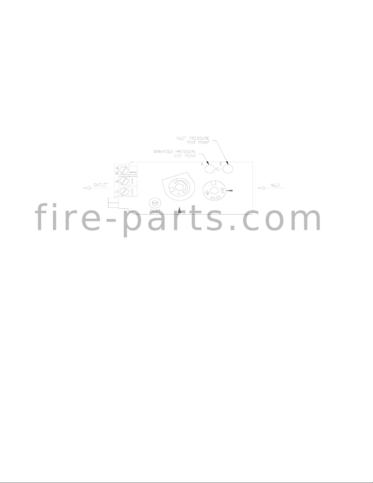
3.3.9.1 Manifold Pressure Regulator Adjustment .....................................................22
3.3.9.2 Pilot Flame Adjustment .................................................................................22
3.3.9.3 Flue Spillage Test .........................................................................................23
3.3.9.4 Altitude Adjustment .......................................................................................24
4.0 MAINTENANCE ......................................................................................................................24
4.1 Maintenance Safety ...................................................................................................... 24
4.2 Recommended Service ................................................................................................24
4.3 Glass Cleaning .............................................................................................................25
4.4 Cleaning of Brass Plated Surfaces ............................................................................... 25
4.5 Cleaning of Gold Plated Surfaces .................................................................................25
4.6 Burner & Pilot Cleaning ................................................................................................25
4.7 Fan Replacement & Electrical Schematic .....................................................................25
4.8 Heater Dis-assembly & Re-assembly ........................................................................... 28
5.0 AUSTRALIAN DRESS GUARD .............................................................................................29
6.0 TROUBLE SHOOTING ...........................................................................................................31
7.0 REPLACEMENT PARTS ........................................................................................................ 34
8.0 OSBURN’S WARRANTY .......................................................................................................36
9.0 LABEL INFORMATION ..........................................................................................................38
/2
1.0 INTRODUCTION
1.1 SPECIFICATIONS
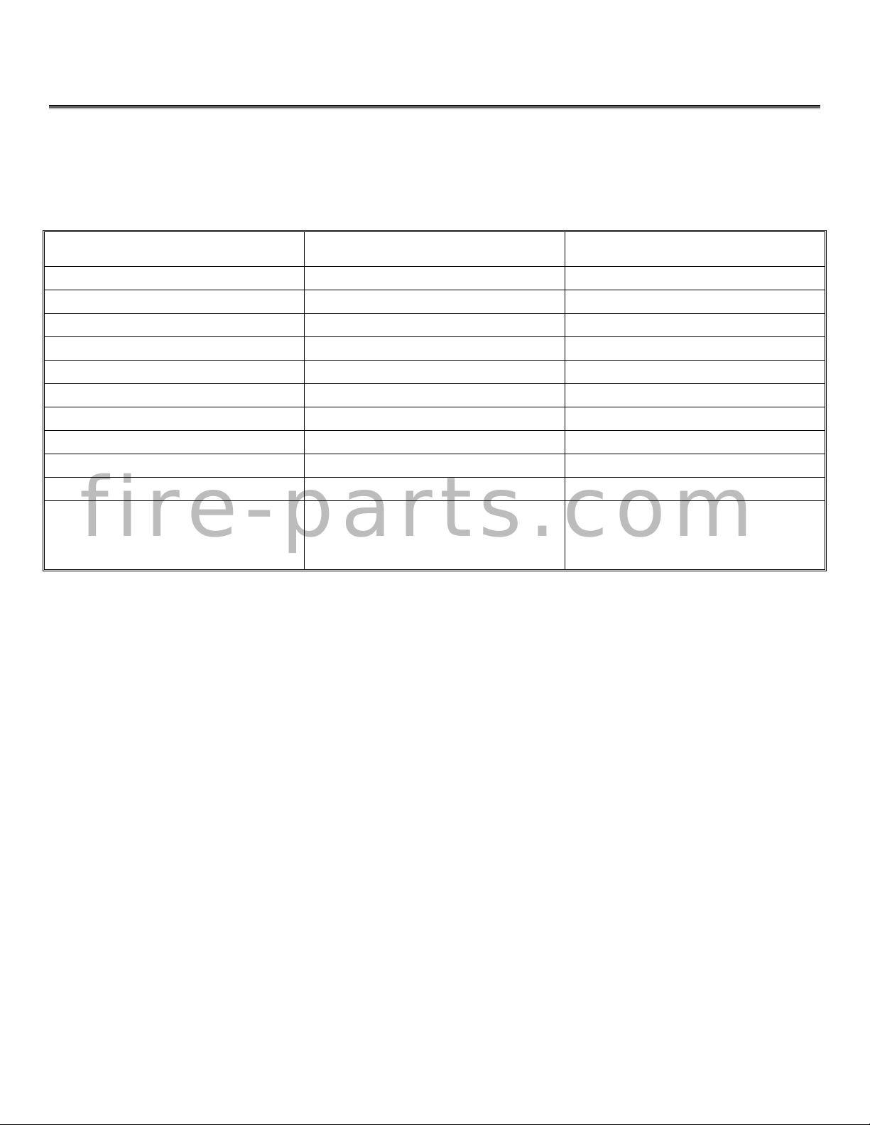
TABLE 1 SPECIFICATIONS
ITEM NATURAL GAS (NG) PROPANE (LPG)
INPUT: 35,000 (36.9 MJ) 35,000 (36.9 MJ)
AFUE: EFFICIENCY: Fan off 64%
MANIFOLD PRESSURE: 3.8” w.c. (0.9 kPa) 10.5” w.c. (2.6 kPa)
GAS INLET SUPPLY PRESSURE: Minimum: 5.0” w.c. (1.2 kPa) Minimum: 11.0” w.c. (2.7 kPa)
Normal: 7.0” w.c. (1.7 kPa) Normal: 13.5” w.c. (3.4 kPa)
Maximum: 13.5” w.c. (3.4 kPa) Maximum: 13.5” w.c. (3.4 kPa)
ORIFICE SIZE: @ 0-4500’ #36 DMS (.107” DIA.) #50 DMS (.070” DIA.)
CONTROL VALVE TYPE: SIT 820 Nova (Variable) SIT 820 Nova (Variable)
SHIPPING WEIGHT: 111 lb. (50 kg) 111 lb. (50 kg)
FLUE OUTLET SIZE: 4” DIA. (102 mm) 4” DIA. (102 mm)
FAN: Variable Speed (110 Volt)
f i r e - p a r t s . c o m
NOTE: AFUE was tested by the Manufacturer.
OPTIONS: Faceplate
Thermostat
Remote Control
Single Speed (240 Volt)
Dual Speed (240 Volt)
/3
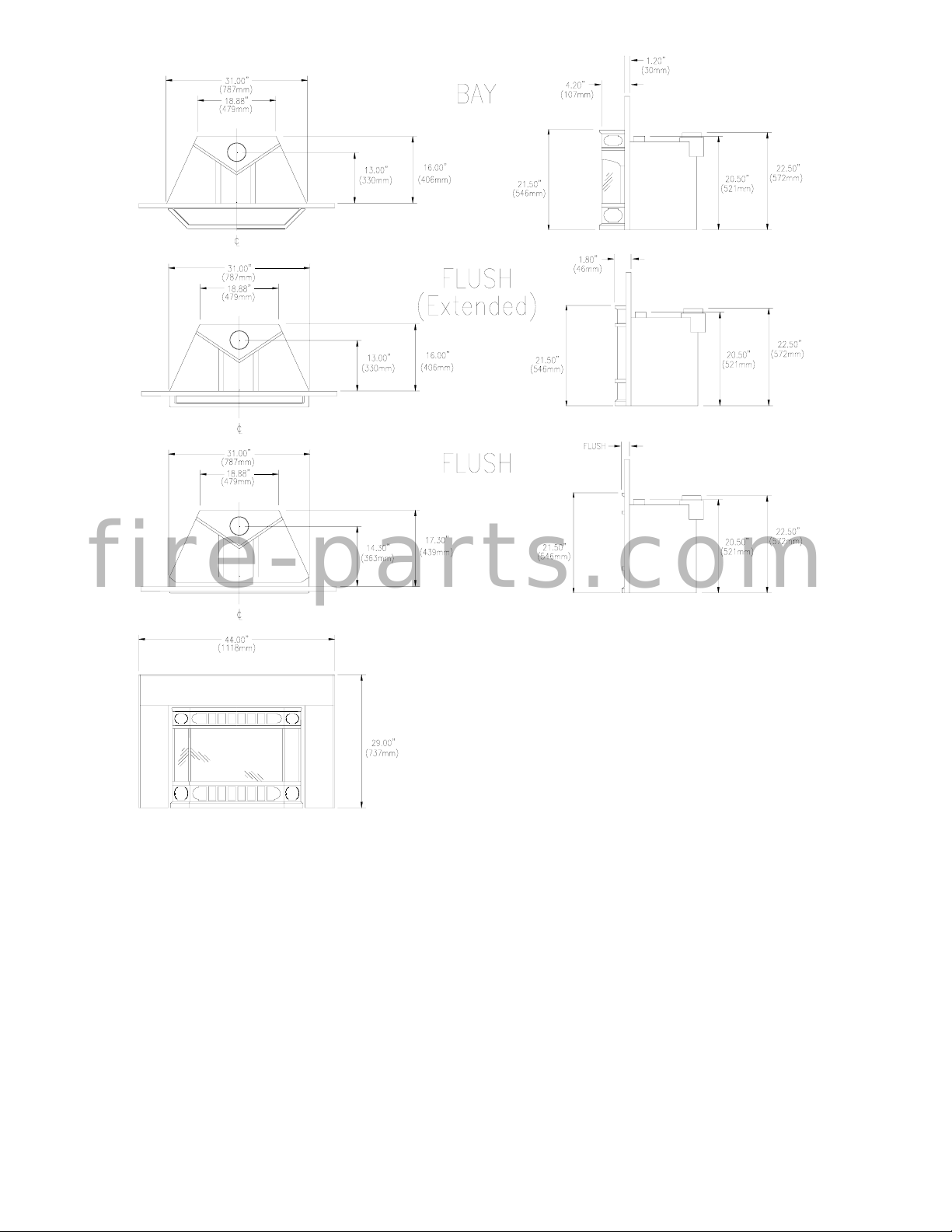
f i r e - p a r t s . c o m
Figure 1
INSTALLATION CODES
Installation must conform to local codes. In the absence of local codes, installation must conform to
the National Fuel Gas Code, ANSI Z233.1 1988, (in the U.S.), or with the current installation code
CAN/CGA B149.1 – M86 (in Canada). In Australia, the Australian Gas Association installation code
for gas burning heaters and equipment must be used. The heater, when installed, must be
electrically grounded in accordance with local codes or, in the absence of local codes, with the
National Electric Code ANSI/NFPA No. 70-1990 (in the U.S.) or with the current CSA C22.1 Canadian
Electrical Code (in Canada). In the state of Massachusetts, this product can only be installed by a
licensed plumber or a licensed gas fitter. Failure to comply will void the warranty.
/4

1.2 FEATURES
Ignition system:
Standing pilot ignition system with thermopile and thermocouple flame detection and piezo igniter.
Gas control:
Gas control valve type:
Automatic millivolt powered combination gas control valve with variable flame control for
convenience and on/off switch. Optional remote on/off wall switch, optional wall thermostat,
and/or optional wireless remote control are available. The gas valve does not require
electricity from an external source.
Fan control;
Variable speed control:
For units equipped with a fan control, the knob controls the fan speed in connection with a heat
sensitive switch which turns on when the heater reaches operating temperature. Turning the
knob counter-clockwise turns it to the “Off” position.
Auto/Off switch: (Single Speed 240 Volt)
For units equipped with a single speed fan switch, the fan may be switched between the
“Automatic” and the “Off” settings.
High/Off/Low: (Dual Speed 240 Volt)
f i r e - p a r t s . c o m
For units equipped with a double speed fan switch, the fan may be switched between the
“High”, “Off”, and the “Low” settings.
Safety controls:
A safety switch will shut the system down in the event of any one of the following conditions:
Incorrectly installed vent system
Blocked vent causing flue spillage
Flow reversal or sustained down draft situation
Drafthood:
The appliance is provided with a drafthood design, which minimizes the effects of down drafts or
flue blockages on the quality of combustion. It will vent out of the appliance upon down draft or
flue blockage and, by design, it exhausts to the same pressure zone as the combustion air inlet
to the appliance.
1.3 INTENDED USE
This appliance is intended to be used as a heater, when installed as an insert for code complying
masonry, or listed factory built solid fuel burning fireplaces which meet the minimum requirements as
described in detail in the installation instructions. This insert is certified for installation in a bedroom
or a bed sitting room where the maximum input is within 50 cubic feet per 1000 Btu/hr, (i.e. 1250
cubic feet). All bedroom installations require the use of wall thermostats.
/5
1.4 GENERAL SAFETY
The appliance must be properly connected to a venting system in accordance with local codes. This
unit must not be connected to a chimney or flue serving any other appliance. It is equipped with a
safety control system to protect against improper venting of flue products.
WARNING: Operation of this insert when not connected to a properly installed and
maintained venting system may result in carbon monoxide poisoning.
Installation and repair should be done by a qualified service person. The appliance should be
inspected before use and at least annually by a professional service technician. Provide adequate
clearances around air openings and allow accessibility clearance for servicing and proper operation.
In Australia, a dress guard has been installed to cover the glass and to protect users against
accidental contact with hot surfaces. Do not operate the appliance without the dress guard in place.
2.0 INTRODUCTION
2.1 OPERATION SAFETY
Inspect the appliance before use. Always keep the appliance area clear and free from combustible
f i r e - p a r t s . c o m
materials, gasoline, and other flammable vapours and liquids. Never obstruct the flow of ventilation
air. Keep the front of the appliance clear of all obstacles and foreign materials. Never obstruct or
modify the air inlet/outlet grilles of the fireplace in any manner.
CAUTION: Children and adults should be alerted to the hazards of high surface of
high surface temperature and should stay away to avoid burns or contact with hot
surfaces. Young children should be carefully supervised when they are in the same
room as the heater. Clothing or other flammable material should not be placed on or
near the unit.
The glass door and top grille must be properly installed prior to operation. Never operate the unit
with the glass door off or broken since this may cause dangerous indoor air pollution. This unit is not
for use with solid fuel. Do not substitute any parts or materials. Do not abuse the glass door.
/6
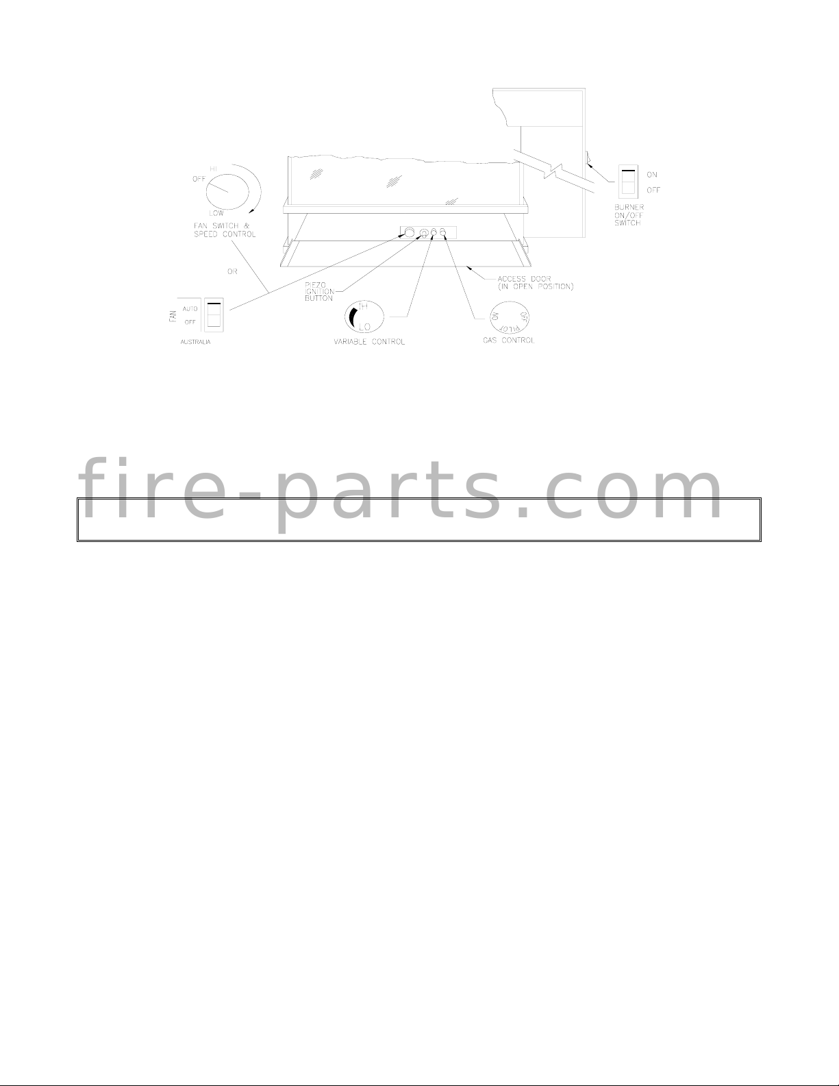
Figure 2
2.2 LIGHTING INSTRUCTIONS
FOR YOUR SAFETY, READ BEFORE LIGHTING
WARNING: If you do not follow these instructions exactly, a fire or explosion may
f i r e - p a r t s . c o m
result causing property damage, personal injury, or loss of life.
A. This appliance is provided with a standing pilot flame. When lighting the pilot, follow these
instructions exactly.
B. BEFORE LIGHTING: smell all around the appliance area for gas. Be sure to smell next to the
floor because some gas is heavier than air and will settle on the floor.
WHAT TO DO IF YOU SMELL GAS
Do not try to light any appliance.
Do not touch any electrical switch: do not use any phone in your home.
Immediately call your gas supplier from a neighbour’s phone. Follow the gas suppliers’
instructions.
If you cannot reach your gas supplier, call the fire department.
C. Use only your hand to push in or turn the gas control knob. Never use tools. If the knob will not
push in or turn by hand, do not try to force or repair it; call a qualified service technician. Forcing or
attempted repair may result in a fire or explosion.
D. Do not use this appliance if any part has been under water. Immediately call a qualified service
technician to inspect the appliance and to replace any part of the control system and any gas control,
which has been under water.
/7
LIGHTING PROCEDURE
1. “STOP!” Red the safety information in the previous section.
2. Set the thermostat to the lowest setting.
3. Turn off all electrical power to the appliance.
4. Open the access door, hinged to open downward, by gently pulling the top toward you.
5. Push in the gas control knob slightly and turn clockwise to the “OFF” position (see Figure 3).
f i r e - p a r t s . c o m
6. Wait a minimum of five minutes to clear out any residual gas. If you then smell gas, STOP!
Follow “B” in the Lighting Instruction section described on the previous page. If you don’t smell
gas, go to the next step.
7. Press in the gas control knob and turn counter-clockwise to the “PILOT” position.
8. Push the control knob in all the way and hold it in. Immediately push the piezo ignition button
(the black button second from the left) repeatedly so that it clocks; continue until the pilot ignites.
Maintain pressure on the knob for about one minute after ignition. Then release the knob; if the
pilot flame goes out repeat step 8; if the pilot flame remains on then turn the knob counterclockwise to the “ON” position.
9. If the pilot lights but will not stay on after several tries, turn the gas control knob to the “OFF”
position and call your service technician or gas supplier. If the control knob does not pop out
when released, STOP – shut off the gas supply to the control valve, and IMMEDIATELY call
your service technician or gas supplier.
10. If equipped with a wall switch, select the “ON” position. If equipped with a thermostat or auxiliary
control, set it to the desired setting.
11. Close the access door by lifting it, allowing the springs to pull it closed.
Figure 3
/8

SHUTDOWN PROCEDURE To turn off the main burner only, turn off the wall switch, thermostat, or On/Off switch located on the
lower right side behind the access door.
For complete shutdown of the appliance, depress the gas control knob and turn it clockwise to the
“OFF” position.
2.3 HEAT OUTPUT ADJUSTMENT
The valve supplied with the appliance has a HI/LO knob to control the heat output and flame height
(see Figures 2 & 3).
2.4 FAN OPERATION
For units equipped with a fan control knob, the knob is located behind the access door and may be
adjusted to the following settings:
OFF: Turn the control fully counter-clockwise until the switch operates.
Variable Speed Setting:
Turn the control to the desired setting. When the knob is turned fully clockwise the fan will be
f i r e - p a r t s . c o m
set to minimum speed.
For units equipped with a fan switch, the fan may be switched between the “Off” and “Automatic”
settings.
2.5 REMOTE CONTROL OPERATION
An optional hand held remote control kit for turning the unit On and Off is also available. Detailed
instructions for the optional Remote Control are included with the kit.
3.0 INSTALLATION
3.1 INSTALLATION & SAFETY NOTES
Read all instructions before starting installation and follow them carefully during installation to ensure
maximum benefit and safety. Failure to follow these instructions will void your warranty and may
present a fire hazard. See the Osburn warranty at the back of this manual for disclaimers regarding
improper installation. This fireplace insert and is components are tested and safe when installed in
accordance with this installation manual. This insert must never be installed in direct contact
with combustible construction.
/9
ELECTRICAL GROUNDING NOTE: This heater fan is equipped with a three-prong (grounding) plug
for your protection against shock hazard and should be plugged directly into a properly grounded
three-prong receptacle. Do not cut or remove the grounding prong from this plug.
WARNING: Do not connect 120 VAC (240 VAC in Australia) to the gas control valve
or its wiring, as this will damage the valve.
3.2 UNPACKING
Please check the appliance carefully for any damaged or missing components (specifically check the
glass condition). Report any problems to your dealer. The insert is shipped with the logs and coals in
separate packages inside the firebox. The faceplate with the leveling screws and the grille kit are
packaged separately. All other standard parts are already in place.
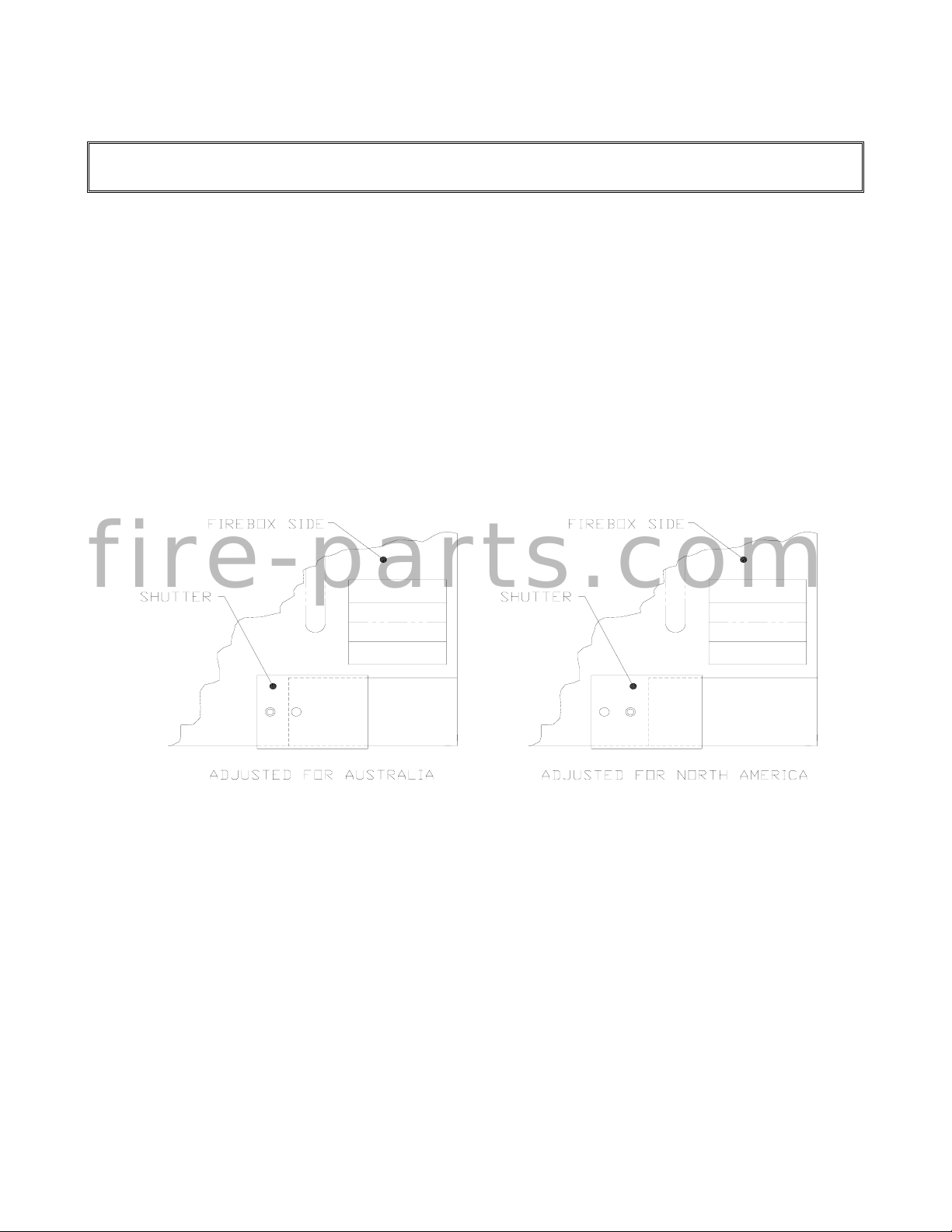
Shutter Adjustment for Australian Units Only:
Before installation the two Shutters on the bottom outside corners of the Firebox must be checked to
ensure their proper positioning (see Figure A).
f i r e - p a r t s . c o m
Figure A
/10
3.3 INSTALLATION
For satisfactory results it is necessary to plan certain aspects of the installation prior to the
appliance’s final positioning. These include the vent system, the gas piping, and the fan siring.
Combustible surfaces such as the hearth, mantle, and facing must also be planned for.
NOTE: All Installations Require Venting.
(In Australia, a minimum vent length of 11’ (3353 mm) must be used off the top of the vent
collar of the appliance).
Minimum enclosures are as follows:
f i r e - p a r t s . c o m
3.3.1 MINIMUM CLEARANCES
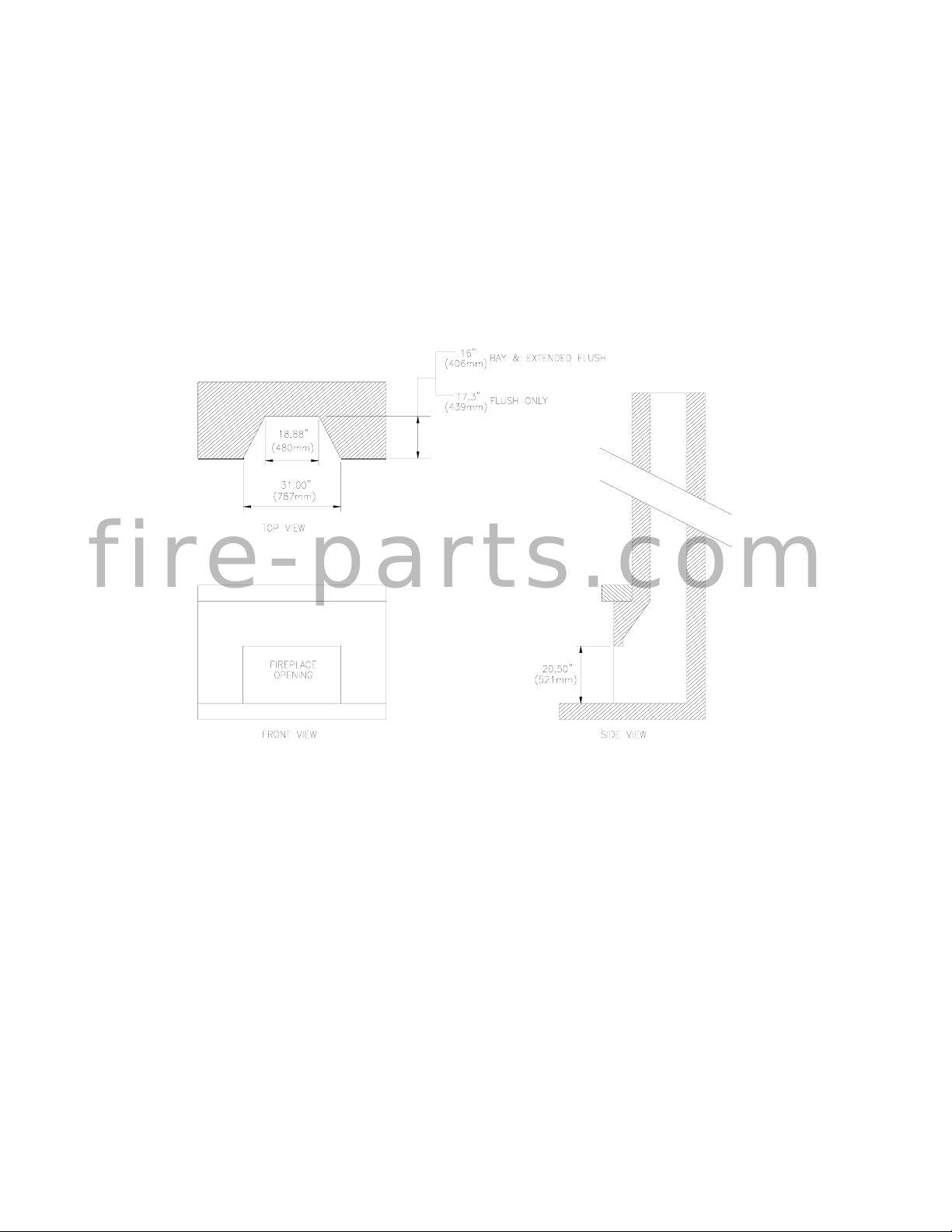
This top venting insert is suitable for installation into masonry fireplaces or into factory built certified
fireplaces which have a gas line knockout and proper floor clearances.
A masonry fireplace must meet the minimum building code requirements or the equivalent for a safe
installation.
Factory built certified fireplaces and their chimneys must be certified and meet local code
requirements. Both must be free from cracks, blockage, creosote deposits, loose mortar, or other
types of deterioration. Inspect the fireplace to ensure the insert will fit (see Figure 4).
Figure 4
/11
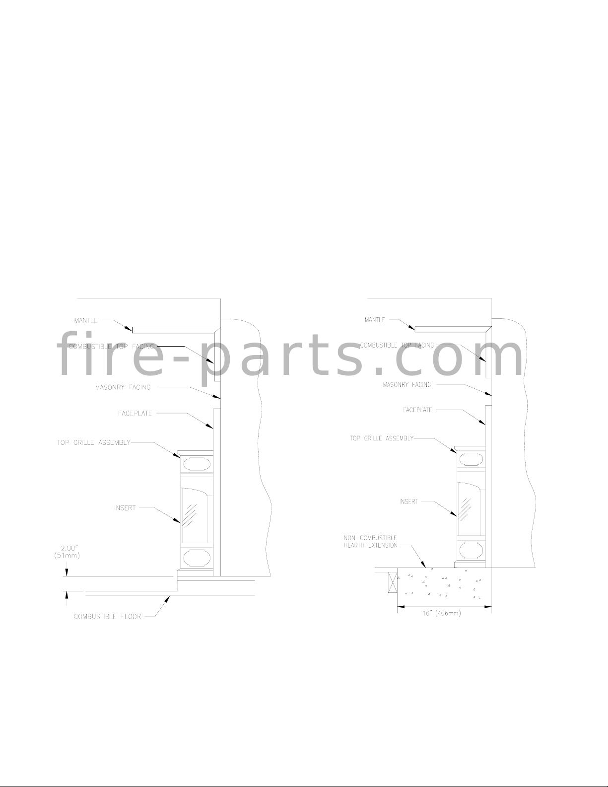
Minimum Clearances to Combustibles A. Sidewall 10” (254mm) measured from glass
B. Ceiling 34” (864mm) measured from top grille
C. Facing Sides 1” (25mm) measured from standard faceplate
D. Top 8.5” (216mm) measured from the top of the grille assembly
E. Floor 2” (51mm) (see Figure 5a)
F. Mantle 12.5” (318mm) measured from top grille to 8” (204mm) mantle
Note: 1. For more mantle options see Figure 6
2. When using paint or lacquer to finish the mantle, such paint or lacquer must be heat
resistant to prevent discolouration.
3. When installing the unit flush to the flooring, there must be a 16” non-combustible hearth
extension (see Figure 5b)
f i r e - p a r t s . c o m
Figure 5a Figure 5b
/12
 Loading...