

Warn Industries VR Installation And Operator's Manual

INSTALLATION AND OPERATOR’S GUIDE
GUIDE D’INSTALLATION ET OPERATEUR
97003A0
VR WINCH
Warn Industries, Inc.
12900 S.E. Capps Road
Clackamas, OR USA 97015-8903
1-503-722-1200 FAX: 1-503-722-3000
www.warn.com
Customer Service / Service Clients: 1-800-543-9276
© 2016 Warn Industries, Inc.
WARN®, the WARN logo are registered trademarks of Warn Industries, Inc.
WARN® et le logo WARN sont des marques
déposées de Warn Industries, Inc.

English .......................................................................... 1
Français ......................................................................18
Español ....................................................................... 34
97003A0
97003A0
WARN INDUSTRIES
1
Every winching situation has the potential for personal injury. In order to minimize
that risk, it is important to read ALL instructions and safety information regarding your
product. Please familiarize yourself with the operation of your winch before using it and
be constantly safety oriented. These instructions provide important safety information
and instructions on how to install and operate your winch.
In this kit you will find the following pieces of literature:
• Winch Installation Guide/ First Time Operation Instructions
• Product Warranty
SAVE THIS MANUAL and other product literature for future reference and review
frequently for continuing safe operation.
Instruct all users of this product to review this manual before operating this product.
Additional Product Literature Available Online:
• Basic Guide to Winching Techniques
• Provides a basic understanding of the winch and teaches basics of proper winching
techniques. It is a valuable resource to help winch safely and efficiently.
• Product Specification and Performance Data
• Provides product specifications, performance data and replacement parts
information.
• Other product literature specific to some products
Go to www.warn.com/corporate/literaturerequest.shtml for additional or replacement
product literature available to view/download.
WARN INDUSTRIES
2
ORIGINAL INSTRUCTIONS
Warn Industries Inc.
12900 SE Capps Road
Clackamas, OR 97015
USA
Customer Service: (800) 543-9276
International Fax: (503) 722-3005
Fax: (503) 722-3000
www.warn.com
WARN® and the WARN l ogo are regi stered tra demarks o f Warn Indust ries, Inc.
© 2016 Warn Industries, Inc.
Winch Installation Guide
TABLE OF CONTENTS:
SAFETY
Symbol Index .............................................................................................................................................................................3
General Safety Precautions ...............................................................................................................................................4-6
INSTRUCTION
Know Your Winch .....................................................................................................................................................................7
Mounting .............................................................................................................................................................................. 8-11
Mount you winch ......................................................................................................................................................8-9
Relocate your control pack...............................................................................................................................10-11
Electrical Connections ......................................................................................................................................................... 12
First Time Operation Instructions ..............................................................................................................................13-15
Final Analysis and Maintenance ..................................................................................................................................... 16
97003A0
97003A0
WARN INDUSTRIES
3
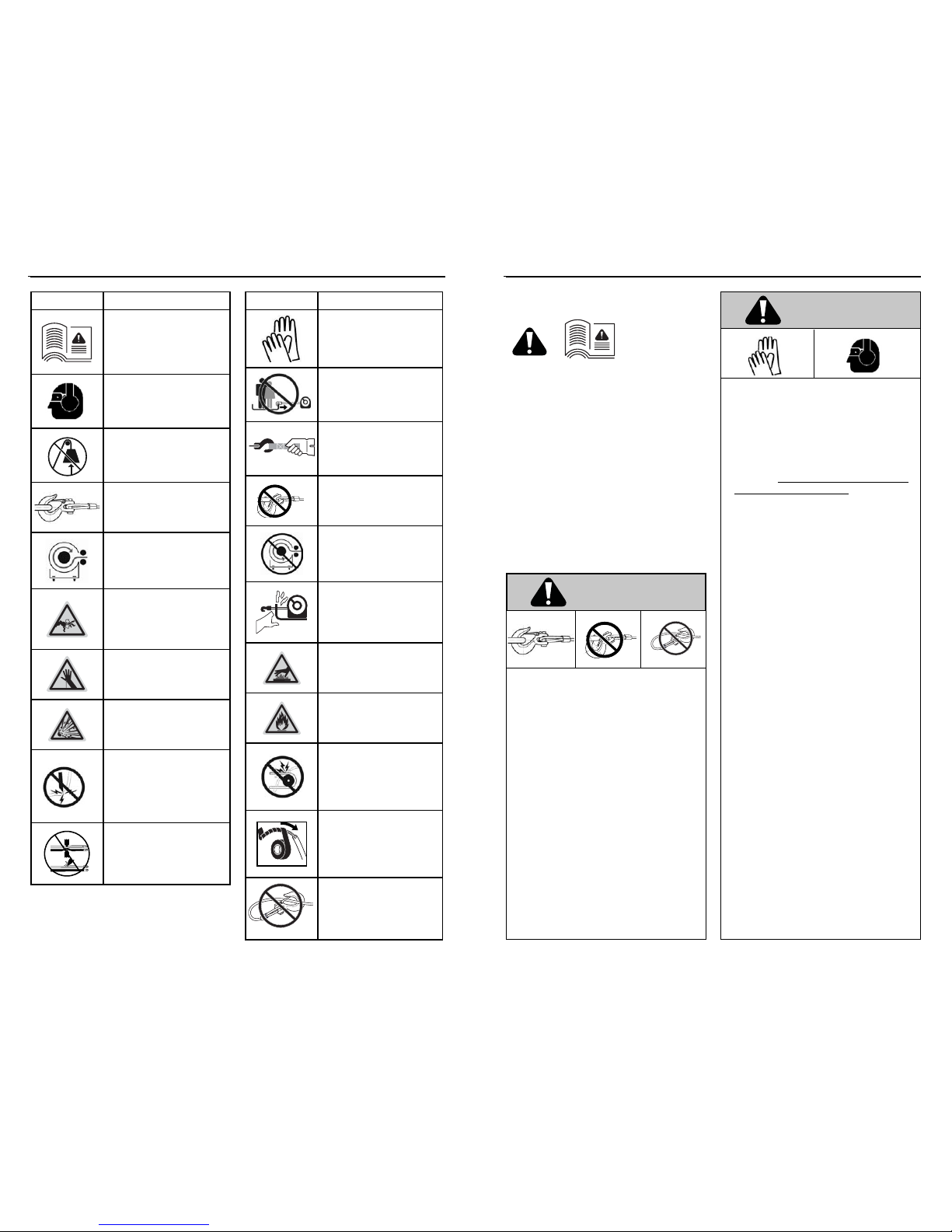
SYMBOL INDEX
SYMBOL EXPLANATION
Read All Product Literature
* Some literature available only
onlinewww.warn.com/corporate/
literaturerequest.shtml.
Always Wear Hearing and
Eye Protection
Never Use Winch as a
Hoist
Properly Seat Load in
Throat of Hook
Wind Rope on Bottom of
Drum
Finger/Fairlead Crushing
Hazard
Hand Piercing/Cutting
Hazard
Explosion/Bursting
Hazard
Never Route Electrical
Cables through Sharp
Edges Hazard
Avoid Installing Electrical
Cables around Pinch and
Wear/Abrasion Points
SYMBOL EXPLANATION
Always Wear Leather
Gloves
Do Not Move People
Always Use Supplied
Hook Strap
Never Apply Load to
Hook Tip or Latch
Never Wind Rope Over
Top of Drum
Fairlead Pinch Point
Hot Surface Hazard
Fire and Burn Hazard
Never Route Electrical
Cables through or near
Moving Parts Hazard
Exposed Wiring Hazard,
Insulate Exposed Wiring
and Terminals
Never Hook Back on
Rope
WARN INDUSTRIES
4
GENERAL SAFETY PRECAUTIONS
As you read these instructions, you will see WARNINGS,
CAUTIONS, NOTICES and NOTES. Each message has a speci c
purpose. WARNINGS are safety messages that indicate
a potentially hazardous situation, which, if not avoided
could result in serious injury or death. CAUTIONS are safety
messages that indicate a potentially hazardous situation
which, if not avoided, could result in minor or moderate
injury. A CAUTION may also be used to alert against unsafe
practice. CAUTIONS and WARNINGS identify the hazard,
indicate how to avoid the hazard, and advise of the probable
consequence of not avoiding the hazard. NOTICES are
messages to avoid property damage. NOTES are additional
information to help you complete a procedure. PLEASE
WORK SAFELY!
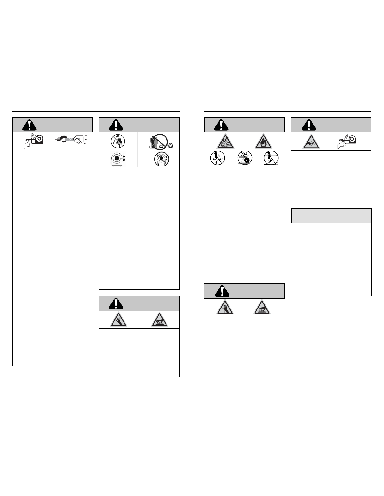
Warnings and Cautions
MOVING PARTS ENTANGLEMENT HAZARD
Failure to observe these instructions could lead to
serious injury or death.
• Always ensure hook latch is closed and not
supporting load.
• Never apply load to hook tip or latch. Apply load only
to the center of hook.
• Never use a hook whose throat opening has
increased, or whose tip is bent or twisted.
• Always use a hook with a latch.
• Always ensure the operator and bystanders are aware
of the stability of the vehicle and/or load.
• Always keep wired remote control lead and power
cord clear of the drum, rope, and rigging. Inspect for
cracks, pinches, frayed wires or loose connections.
Damaged components must be replaced before
operation.
• Always pass remote lead thru window when used in
vehicle.
• Never hook back on rope.
MOVING PARTS ENTANGLEMENT HAZARD
Failure to observe these instructions could lead to
serious injury or death.
General Safety:
• Always Know Your Winch. Take time to fully read the
Instructions and/or Operations Guide, and/or Basic Guide to
Winching Techniques, in order to understand your winch and
its operations, found online at http://www.warn.com/
corporate/literaturerequest.shtml.
• Never exceed winch or winch rope rated capacity.
Double line using a snatch block to reduce winch load.
• Always wear heavy leather gloves when handling
winch rope.
• Never use winch or winch rope for towing. Shock
loads can damage, overload and break rope.
• Never use a winch to secure a load.
• Never operate this winch when under the in uence of
drugs, alcohol or medication.
• Never operate this winch if you are under 16 years of
age.
Installation Safety:
• Always choose a mounting location that is su ciently
strong to withstand the maximum pulling capacity of
your winch.
• Always use class 8.8 metric (grade 5) or better
hardware.
• Never weld mounting bolts.
• Always use factory approved mounting hardware,
components, and accessories.
• Never use bolts that are too long.
• Always con rm required bolt length to ensure proper
thread engagement.
• Always complete the winch installation and hook
attachment before installing the wiring.
• Always keep hands clear of winch rope, hook loop,
hook and fairlead opening during installation,
operation, and when spooling in or out.
• Always position fairlead with warning readily visible
on top.
• Always prestretch rope and respool under load before
use. Tightly wound rope reduces chances of “binding”,
which can damage the rope.
WARNING
WARNING
97003A0
97003A0
WARN INDUSTRIES
5
GENERAL SAFETY PRECAUTIONS
MOVING PARTS ENTANGLEMENT HAZARD
Failure to observe these instructions could lead to
serious injury or death.
Winching Safety:
• Always inspect winch rope, hook, and slings before
operating winch. Frayed, kinked or damaged winch
rope must be replaced immediately. Damaged
components must be replaced before operation.
Protect parts from damage.
• Always remove any element or obstacle that may
interfere with safe operation of the winch.
• Always be certain the anchor you select will
withstand the load and the strap or chain will not
slip.
• Always use supplied hook strap whenever spooling
winch rope in or out, during installation and during
operation.
• Always require operators and bystanders to be
aware of vehicle and or load.
• Always be aware of stability of vehicle and load
during winching, keep others away. Alert all
bystanders of an unstable condition.
• Always unspool as much winch rope as possible
when rigging. Double line or pick distant anchor
point.
• Always take time to use appropriate rigging
techniques for a winch pull.
• Never touch winch rope or hook while someone else
is at the control switch or during winching operation.
• Never engage or disengage clutch if winch is under
load, winch rope is in tension or drum is moving.
• Never touch winch rope or hook while under tension
or under load.
• Always stand clear of winch rope and load and keep
others away while winching.
• Never use vehicle to pull load on winch rope.
Combined load or shock load can damage, overload
and break rope.
• Never wrap winch rope back onto itself. Use a
choker chain or tree trunk protector on the anchor.
FALLING OR CRUSHING HAZARD
Failure to observe these instructions could lead to
serious injury or death.
•
Always stand clear, keep hands clear, keep others away.
• Never operate winch with less than 5 wraps of rope
around the drum. Rope could come loose from the
drum, as the rope attachment to the drum is not
designed to hold a load.
• Never use winch as a hoist or to suspend a load.
• Always be certain anchor will withstand load, use
appropriate rigging and take time to rig correctly.
• Never use winch to lift or move persons.
• Never use excessive e ort to freespool winch rope.
•
Always use proper posture/lifting technique or get
lifting assistance while handling and installing product.
• Always wind the winch rope on bottom (mountside)
of drum.
• Never wind rope over top of drum.
• Always spool the winch rope onto the drum in the
direction speci ed by the drum rotation labels on the
winch and/or in the documentation. This is required
for the automatic brake (if so equipped) to function
properly.
CUT AND BURN HAZARD
Failure to observe these instructions could lead to
serious injury or death.
To avoid injury to hands and ngers:
• Always wear heavy leather gloves when handling
winch rope.
• Always be aware of possible hot surfaces at winch
motor, drum or rope during or after winch use.
WARNING WARNING
WARNING
WARN INDUSTRIES
6
GENERAL SAFETY PRECAUTIONS
AVOID WINCH AND EQUIPMENT DAMAGE
• Always avoid side pulls which can pile up winch rope
at one end of the drum. This can damage winch rope
or winch.
• Always ensure the clutch is fully engaged or
disengaged.
• Always use care to not damage the vehicle frame
when anchoring to a vehicle during a winching
operation.
• Never submerge winch in water.
• Always store the remote control in a protected, clean,
dry area.
NOTICE
MOVING PARTS ENTANGLEMENT HAZARD
Failure to observe these instructions could lead to
minor or moderate injury.
To avoid injury to hands or ngers:
• Never leave remote control where it can be activated
during free spooling, rigging, or when the winch is not
being used.
• Never leave the winch remote control plugged in
when installing, freespooling, rigging, servicing or
when the winch is not being used.
CHEMICAL AND FIRE HAZARD
Failure to observe these instructions could lead to
serious injury or death.
• Always remove jewelry and wear eye protection.
• Never route electrical cables across sharp edges.
• Never route electrical cables near parts that get hot.
• Never route electrical cables through or near moving
parts.
• Always place the supplied terminal boots on
wires and terminals as directed by the installation
instructions.
• Never lean over battery while making connections.
• Never route electrical cables over battery terminals.
• Never short battery terminals with metal objects.
• Always verify area is clear of fuel lines, fuel tank,
brake lines, electrical wires, etc., when drilling.
• Always consult operator’s manual for proper wiring
details.
• Always insulate and protect all exposed wiring and
electrical terminals.
CUT AND BURN HAZARD
Failure to observe these instructions could lead to
minor or moderate injury.
• Never let winch rope slip through your hands.
CAUTION
WARNING CAUTION
Safety
When installing your WARN winch system, read
and follow all mounting and safety instructions.
Always use caution when working with electricity
and remember to verify that no exposed electrical
connections exist before energizing your winch
circuit.
For specifications and performance data, refer to
the specification sheet supplied with your winch.
97003A0
97003A0
WARN INDUSTRIES
7
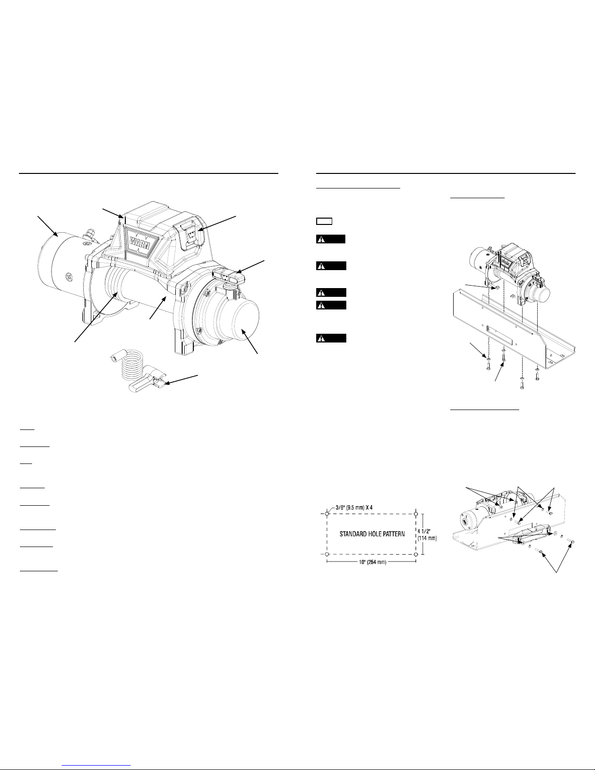
KNOW YOUR WINCH
Know Your Winch
Before you begin, you should familiarize yourself with your WARN winch and each of its components:
Motor: The winch motor is powered by the vehicle’s battery. The motor provides power to the gear
mechanism, which turns the winch drum and winds the winch rope.
Winch Drum: The winch drum is the cylinder onto which the winch rope feeds. The drum is driven by the
motor and drive train. Its direction can be changed using the remote control.
Rope*: The winch rope’s diameter and length are determined by the winch’s load capacity and
design. Wrapped around the winch drum and fed through the fairlead, the winch rope is
looped at the end to accept the hook’s clevis pin.
Gear Train: The reduction gear converts the winch motor power into a large pulling force. The gear train
design makes it possible for the winch to be lighter and more compact.
Clutch Lever: The clutch allows the operator to manually disengage the spooling drum from the gear train,
enabling the drum to rotate freely (known as “freespooling”). Engaging the clutch “locks” the
winch drum back onto the gear train.
Remote Socket: The remote socket is where the operator plugs in the wired remote control or optional
wireless remote receiver, in order to control the winch.
Control Pack*: Using electrical power from the vehicle’s battery, the control pack’s contactor switches
power to the motor, enabling the operator to change the direction of the winch drum
rotation.
Remote Control: The remote control plugs into the winch control pack, via the remote socket, allowing the
operator to control the winch direction, as well as stand well clear of the wire rope while
operating the winch.
Motor
Control Pack
Remote Socket
Clutch Lever
Transmission
(Gear Train)
Rope
Winch Drum
Remote Control
Figure 1
WARN INDUSTRIES
8
MOUNTING
Mounting Orientation and Hardware
Feet down mounting:
• (4) 3/8 Lock Washer
• (4) 3/8-16 x 1-1/4 Hex Head Bolt
• (4) 3/8-16 Square Nut
For feet forward mounting:
• (2) 3/8-16 x 1-1/4 Hex Head Bolt
• (2) 3/8 Washer
• (2) 3/8-16 x 1-3/4 Hex Head Bolt
• (4) 3/8-16 Square Nut
• (4) 3/8 Lock Washer
Step 1 - Mount the Winch
Winch mounting kits are available to satisfy nearly
all applications. For information on available kits,
contact your WARN® product dealer.
NOTICE
For optimal performance and the results you expect,
WARN® mounting plates are strongly recommended.
CAUTION
To prevent accidental activation of the winch
and serious injury, complete the winch installation and attach
the hook before installing the wiring.
WARNING
Always choose a mounting location that is
su ciently strong enough to withstand the maximum pulling
capacity of your winch.
WARNING
Never use bolts that are too long.
WARNING
Always spool the winch rope onto the drum
in the direction speci ed by the drum rotation labels on the
winch and/or in the documentation. This is required for the
automatic brake (if so equipped) to function properly.
WARNING
Always wind the winch rope on the bottom
(mount side) of the drum.
This winch should always be mounted in a
horizontal orientation with the rope winding on
and off the drum on the mount side (bottom) of the
drum.
Correct rotation is required for the automatic
brake to function properly. Horizontal mounting
helps prevent the rope from piling up on one end of
the drum which can damage the winch.
Always use recommended bolt and washer
combinations torqued to recommended levels.
Specifications listed below. Mounting system will
dictate bolt length.
Mounting Bolt Pattern:
Standard: 10”x 4.5” (54 mm x 114.3 mm)
Smooth and at mounting sur face, minimum
thickness = 1/4” (6.4 mm)
(4) 3/8-16
Square Nut
(4) 3/8-16 x 1-1/4
Hex Head Bolt
(4) 3/8 Lock
Washer
(4) 3/8 Lock
Washer
(2) 3/8-16 x 1-3/4
Hex Head Bolt
(4) 3/8-16
Square Nut
(2) 3/8 Washer
(2) 3/8-16 x 1-1/4
Hex Head Bolt
97003A0
97003A0
WARN INDUSTRIES
9
MOUNTING
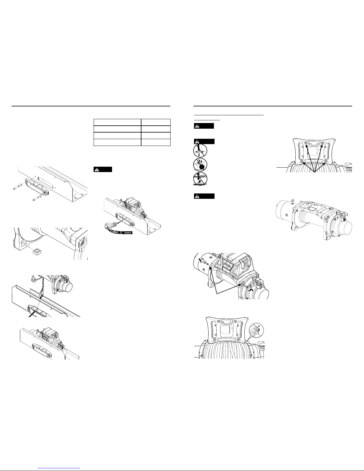
Mount Winch:
1. Choose a mounting location that is sufficiently
strong enough to withstand the maximum
pulling capacity of your winch.
2. Install your mounting bracket per your specific
mounting kit instructions.
3. Fasten fairlead* to mounting bracket using the
hardware specified for your specific mounting
orientation. See the Mounting Orientation
section for hardware specifics.
4. Set the (4) square nuts into pockets of winch
feet.
5. Thread the hook loop end of the rope through
the opening of mounting bracket and fairlead.
6. Set winch in mount.
7. See table below to confirm required bolt length.
Plate Thickness Bolt Length
7 mm (1/4”) 32 mm (1 1/4”)
10 mm (3/8”) 40 mm (1 5/8”)
13 mm (1/2”) 40 mm (1 5/8”)
8. Review mounting orientation for bolt sizing.
9. Install bolts and tighten to 41 to 47 Nm (30-35
ft. lbs.).
WARNING
Always con rm required bolt length to
ensure proper thread engagement.
10. Attach hook to winch rope loop.
11. Attach hook strap to hook.
12. Mounting your winch is now complete. Check
all hardware to be sure it is tight and to torque.
You can now move on to Install the Wiring.
WARN INDUSTRIES
10
MOUNTING
WARNING
To prevent serious injury or death.
Always place the supplied terminal boots on wires and
terminals as directed by the installation instructions.
WARNING
To prevent serious injury or death from
electrical re:
Never route electrical cables across sharp
edges.
Never route electrical cables near parts that
get hot.
Never route electrical cables through or near
moving parts.
Avoid pinch and wear/abrasion points when
installing all electrical cables.
WARNING
Never mount contactor with electrical
terminals touching metal objects.
1. Disconnect the vehicle battery cables,
negative terminal first. All work with electrical
wires and cables must be completed with the
battery completely disconnected from the
vehicle wiring.
2. Determine control pack mounting location.
Remove the control pack
1. Remove the two front tie bolts.
2. Tilt the control pack tie plate up and away from
winch drum. NOTE: You may need to loosen the two
rear tie bolts in order to do this.
Step 2 - (Optional) Relocating the
Control Pack
3. Remove the four control pack screws and gently
lift control pack off winch tie plate.
4. Position the control pack tie plate back into
position and reinstall the two front tie bolts.
5. Tighten ALL four tie bolts to torque of 25-30 Nm.
97003A0
97003A0
WARN INDUSTRIES
11
MOUNTING
Template NOT to scale
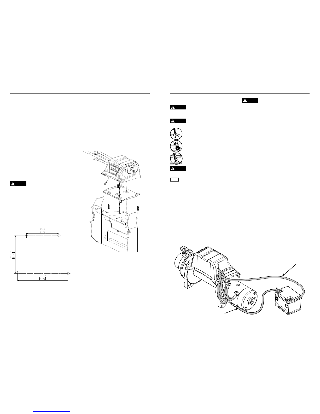
Mount control pack
It is recommended that the control pack be
mounted on a solid mounting surface and easily
accessible.
The control pack should be in a location that is as
clean and dry as possible.
Ensure the control pack mounting location
selected provides sufficient clearance from all metal
structures. Exact location will vary depending on
the vehicle.
To determine the winch motor cable assembly
and ground wire routing path, verify the path will
allow the winch motor cable assembly and ground
wire to be routed avoiding sharp edges, parts that
get hot and moving parts. Consider chassis flex and
vibration which might damage cable.
NOTE: You may need to adjust your original desired
control pack mounting location, due to specific
wiring lengths.
WARNING
Always verify area is clear of fuel lines, fuel
tank, brake lines, electrical wires, etc., when drilling.
After determining control pack mounting
location, you are ready to mount your control pack.
Mount to your vehicle
1. Use the template below as a guide for drilling
mounting holes. Holes should be drilled for M6
diameter bolt. WARNING! Be sure to check the area
before you drill to avoid hitting any electrical cables or
gas lines.
3. Secure the control pack using the supplied
hardware.
Mount to your bumper
1. Line up the control pack mounting holes
with holes on control pack mounting bracket
(Control pack mounting bracket kit sold
separately. Contact a Warn Industries
customer service representative at
1.800.543.9276 or visit www.warn.com).
2. Using hardware in kit, secure control pack to
control pack mounting plate.
3. Secure control pack assembly to bumper with
remaining hardware.
WARN INDUSTRIES
12
ELECTRICAL CONNECTIONS
Step 3 - Install the Wiring
WARNING
To prevent serious injury or death. Always
place the supplied terminal boots on wires and terminals as
directed by the installation instructions.
WARNING
To prevent serious injury or death from
electrical re:
Never route electrical cables across sharp edges.
Never route electrical cables near parts that get
hot.
Never route electrical cables through or near
moving parts.
Avoid pinch and wear/abrasion points when
installing all electrical cables.
WARNING
Always insulate and protect all exposed wiring
and electrical terminals.
NOTICE
A fully charged battery and good connections are
essential to the proper operation of your winch. The minimum
requirement for a 12 volt DC battery is 650 Cold Cranking Amps.
Route battery connection cables in areas which
will not cause them to chafe or cut through the
insulation causing a potential short circuit.
The winch power wire must be routed to the
battery. A direct battery connection of the power
(red) and ground (black) cable is required. WARNING!
Do not connect ground to vehicle chassis.
Routing the battery cables may require removal
of vehicle facia or body parts.
Always route battery cables along a path that
allows the cables to be secured with zip ties.
WARNING
Loose or unsecured power cables can cause
serious injury or death.
Always protect power cables from sharp edges,
areas that get too hot to touch with your hand and
any moving parts.
1. Plan the routing path.
2. Loosely secure power cables along path.
3. Confirm power cables are protected from sharp
edges, heat and moving parts. Consider chassis
flex and vibration which might damage cable.
4. Carefully inspect electrical cable routing. Zip
tie and secure electrical cables. Zip ties should
be snug, but not cutting into wire insulation.
Use electrical tape, pieces of rubber hose or
electrical conduit to protect electrical cables
and wire harness where needed to avoid
electrical cable insulation wear or abrasion.
5. Attach battery cables, red (positive) cable
FIRST, black (negative) second. Install boots
as appropriate to protect connections. Torque
battery terminal fasteners as directed by vehicle
service manual.
Upon completion of installation, check winch for
proper operation.
Power
(72” long red)
Cable
Ground (72” long black) Wire
97003A0
97003A0
 Loading...